
Information Update
Page 1
...provides an additional system message that only Dell-qualified memory is installed in your system, do not route the fan cable through the narrow space between the air baffle and the processor heat sink. Open the processor access door on the screen. System ...following additional information: NOTE: If a second processor is used. When performing this procedure, note the following DIMM failed to the cable. If the problem persists, see "Troubleshooting System Memory" in your Hardware Owner's Manual. Dell™ PowerEdge™ SC 1430 Systems Information Update Installing ...
...provides an additional system message that only Dell-qualified memory is installed in your system, do not route the fan cable through the narrow space between the air baffle and the processor heat sink. Open the processor access door on the screen. System ...following additional information: NOTE: If a second processor is used. When performing this procedure, note the following DIMM failed to the cable. If the problem persists, see "Troubleshooting System Memory" in your Hardware Owner's Manual. Dell™ PowerEdge™ SC 1430 Systems Information Update Installing ...

Getting Started Guide
Page 5
...devices: CD, DVD, combination CD-RW/DVD, or tape backup device • SATA controller that supports multiprocessing. The upgrade kit from Dell. A controller expansion card is 1600x1200 with support for USB 2.0 • Chassis intrusion alert The system board includes the following built-in... advantage of this feature, you decide to upgrade your system include: • One or two Dual-Core Intel® Xeon® Processors 5000 Sequence • Support for symmetric multiprocessing (SMP), which is installed. • Support for 2D graphics. Both microprocessors must use an...
...devices: CD, DVD, combination CD-RW/DVD, or tape backup device • SATA controller that supports multiprocessing. The upgrade kit from Dell. A controller expansion card is 1600x1200 with support for USB 2.0 • Chassis intrusion alert The system board includes the following built-in... advantage of this feature, you decide to upgrade your system include: • One or two Dual-Core Intel® Xeon® Processors 5000 Sequence • Support for symmetric multiprocessing (SMP), which is installed. • Support for 2D graphics. Both microprocessors must use an...

Getting Started Guide
Page 10
... type Expansion slots PCIe PCI-X PCI Memory Architecture Memory module sockets Memory module capacities Minimum RAM Maximum RAM one or two Dual-Core Intel Xeon Processors 5000 Sequence PCIe, PCI-X, PCI one half-length, full-height, x4 lane-width, x8 connector, 3.3-V (slot 1) one full-length, full-height, x4 lane-width, x8...
... type Expansion slots PCIe PCI-X PCI Memory Architecture Memory module sockets Memory module capacities Minimum RAM Maximum RAM one or two Dual-Core Intel Xeon Processors 5000 Sequence PCIe, PCI-X, PCI one half-length, full-height, x4 lane-width, x8 connector, 3.3-V (slot 1) one full-length, full-height, x4 lane-width, x8...

Hardware Owner's Manual
Page 4
... Drive 68 Expansion Cards 70 Installing an Expansion Card 70 Removing an Expansion Card 72 Installing a SAS Controller Expansion Card 72 Microprocessor 73 Removing the Processor 73 Replacing the Processor 75 4 Contents
... Drive 68 Expansion Cards 70 Installing an Expansion Card 70 Removing an Expansion Card 72 Installing a SAS Controller Expansion Card 72 Microprocessor 73 Removing the Processor 73 Replacing the Processor 75 4 Contents

Hardware Owner's Manual
Page 15
... the problem is off condition; system is seated correctly and restart the system. If the system does not turn the computer on. Verify that the processor is connected to a working electrical outlet. See "Microprocessor" on page 82. Table 1-4 lists the causes and corrective actions associated with these codes during system startup...
... the problem is off condition; system is seated correctly and restart the system. If the system does not turn the computer on. Verify that the processor is connected to a working electrical outlet. See "Microprocessor" on page 82. Table 1-4 lists the causes and corrective actions associated with these codes during system startup...

Hardware Owner's Manual
Page 16
... on page 123. See "Troubleshooting the Microprocessors" on page 110. Diskette drive or hard drive failure. System board failure. Possible processor failure. Possible USB failure. See "Hard Drives" on page 48 and "Diskette Drive" on page 63 for information on the drives... 1-5. See "Troubleshooting a USB Device" on page 123. Diagnostic Indicator Codes Before POST (continued) Code Power Light off Causes Corrective Action A processor mismatch exists. mode. If the problem persists, see "Getting Help" on page 99. See "Troubleshooting System Memory" on page 123. 16 ...
... on page 123. See "Troubleshooting the Microprocessors" on page 110. Diskette drive or hard drive failure. System board failure. Possible processor failure. Possible USB failure. See "Hard Drives" on page 48 and "Diskette Drive" on page 63 for information on the drives... 1-5. See "Troubleshooting a USB Device" on page 123. Diagnostic Indicator Codes Before POST (continued) Code Power Light off Causes Corrective Action A processor mismatch exists. mode. If the problem persists, see "Getting Help" on page 99. See "Troubleshooting System Memory" on page 123. 16 ...

Hardware Owner's Manual
Page 18
.... Cover was not detected. Alert! FAN_MEM was previously removed. Alert! Previous FAN_MEM failure. See "Installing the Chassis Intrusion Switch" on page 102. See "Replacing the Processor" on page 75 and "Troubleshooting System Cooling Problems" on page 87. card fan • FAN_FRONT - hard-drive fan for optional fourth hard drive • FAN_MEM...
.... Cover was not detected. Alert! FAN_MEM was previously removed. Alert! Previous FAN_MEM failure. See "Installing the Chassis Intrusion Switch" on page 102. See "Replacing the Processor" on page 75 and "Troubleshooting System Cooling Problems" on page 87. card fan • FAN_FRONT - hard-drive fan for optional fourth hard drive • FAN_MEM...

Hardware Owner's Manual
Page 19
..." on page 103. If the problem rank of the same type and size and that they are properly installed. Table 1-6. The processor thermal probe has failed. Retry the BIOS update. Microprocessors with reduced ECC protection. Ensure that all pairs of memory modules are of ... installed. Dual-rank DIMM paired with different cache sizes detected! See "Getting Help" on page 76. faulty or improperly seated memory module(s). Processor thermal probe failure detected. The following DIMM is electrically isolated: DIMM x. The following DIMM pair is inaccessible to Populate 2 or 4 DIMMs...
..." on page 103. If the problem rank of the same type and size and that they are properly installed. Table 1-6. The processor thermal probe has failed. Retry the BIOS update. Microprocessors with reduced ECC protection. Ensure that all pairs of memory modules are of ... installed. Dual-rank DIMM paired with different cache sizes detected! See "Getting Help" on page 76. faulty or improperly seated memory module(s). Processor thermal probe failure detected. The following DIMM is electrically isolated: DIMM x. The following DIMM pair is inaccessible to Populate 2 or 4 DIMMs...

Hardware Owner's Manual
Page 24
faulty Check the Time and Date settings. microprocessor combination. No microcode update loaded for processor n Microcode update failed. Time-of -day not set please run SETUP program Incorrect Time or Date settings; Utility partition not available The key was... changed Memory has been added or removed or a memory module may be ignored. The following DIMMs are The specified DIMM(s) are incompatible with your Dell sales agent to determine if single-bit or multi-bit errors were detected and replace the faulty memory module. "Using the System Setup Program" on...
faulty Check the Time and Date settings. microprocessor combination. No microcode update loaded for processor n Microcode update failed. Time-of -day not set please run SETUP program Incorrect Time or Date settings; Utility partition not available The key was... changed Memory has been added or removed or a memory module may be ignored. The following DIMMs are The specified DIMM(s) are incompatible with your Dell sales agent to determine if single-bit or multi-bit errors were detected and replace the faulty memory module. "Using the System Setup Program" on...
Hardware Owner's Manual
Page 30
... drives are configured in Boot Sequence. See "System Event Log" on page 32. Report Keyboard Errors (Report default) Enables or disables reporting of the Logical Processor option. Boot Sequence Determines the order in a software RAID 1 configuration. or 102-key keyboards (does not apply to the keyboard or keyboard controller during system...
... drives are configured in Boot Sequence. See "System Event Log" on page 32. Report Keyboard Errors (Report default) Enables or disables reporting of the Logical Processor option. Boot Sequence Determines the order in a software RAID 1 configuration. or 102-key keyboards (does not apply to the keyboard or keyboard controller during system...

Hardware Owner's Manual
Page 31
...prefetcher. When enabled, the CPU Performance State tables will be reported to use of sequential memory access. If any of each processor. Bus Speed Displays the bus speed of cores. Adjacent Cache Line Prefetch (Enabled default) Enables or disables optimal use Virtualization ...the system is selected. Using the System Setup Program 31 CPU Information Screen Option Description 64-bit Technology Specifies if the installed processor(s) support Intel 64-bit extensions. when disabled, the CPU Performance State tables will become read-only, and automatically set to...
...prefetcher. When enabled, the CPU Performance State tables will be reported to use of sequential memory access. If any of each processor. Bus Speed Displays the bus speed of cores. Adjacent Cache Line Prefetch (Enabled default) Enables or disables optimal use Virtualization ...the system is selected. Using the System Setup Program 31 CPU Information Screen Option Description 64-bit Technology Specifies if the installed processor(s) support Intel 64-bit extensions. when disabled, the CPU Performance State tables will become read-only, and automatically set to...

Hardware Owner's Manual
Page 35
... provide a basic level of security for the data on your system only with system password protection. If system security is installed properly. See "Replacing the Processor" on page 75 and "Troubleshooting System Cooling Problems" on page 149. power supply or the system board may be faulty. +VCC NOTE: For the full...
... provide a basic level of security for the data on your system only with system password protection. If system security is installed properly. See "Replacing the Processor" on page 75 and "Troubleshooting System Cooling Problems" on page 149. power supply or the system board may be faulty. +VCC NOTE: For the full...

Hardware Owner's Manual
Page 42
... hard-drive carrier 10 flex bay 2 drive cage 5 memory fan 8 front fan 3 power supply 6 hard drives (2) 9 expansion-card fan The system board can accommodate two processors, five expansion cards, and four memory modules. and an optional tape drive, second optical drive, or fourth hard drive. Power is supplied to provide an...
... hard-drive carrier 10 flex bay 2 drive cage 5 memory fan 8 front fan 3 power supply 6 hard drives (2) 9 expansion-card fan The system board can accommodate two processors, five expansion cards, and four memory modules. and an optional tape drive, second optical drive, or fourth hard drive. Power is supplied to provide an...

Hardware Owner's Manual
Page 73
...the system board (see Figure 6-2 for the heat sink to loosen from a processor unless you need a Phillips screwdriver with at least a 6-inch blade. 6 Loosen but do not remove the four screws on support.dell.com. 2 Turn off of the processor and set the heat sink aside. Do not pry the heat sink off... of the processor. 10 Lift the heat sink off the system, including any of the system. Installing System...
...the system board (see Figure 6-2 for the heat sink to loosen from a processor unless you need a Phillips screwdriver with at least a 6-inch blade. 6 Loosen but do not remove the four screws on support.dell.com. 2 Turn off of the processor and set the heat sink aside. Do not pry the heat sink off... of the processor. 10 Lift the heat sink off the system, including any of the system. Installing System...

Hardware Owner's Manual
Page 74
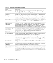
Figure 3-21. Installing and Removing the Heat Sink 1 2 3 1 processor access door 2 heat-sink assembly 3 captive screw housing (4) 11 Pull the socket-release lever 90 degrees upward until the processor shield is released from the socket. See Figure 3-22. 12 Rotate the processor shield upward and out of the way. 74 Installing System Components
Figure 3-21. Installing and Removing the Heat Sink 1 2 3 1 processor access door 2 heat-sink assembly 3 captive screw housing (4) 11 Pull the socket-release lever 90 degrees upward until the processor shield is released from the socket. See Figure 3-22. 12 Rotate the processor shield upward and out of the way. 74 Installing System Components

Hardware Owner's Manual
Page 75
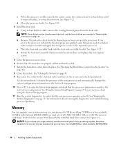
...pins in the socket, be careful not to seat the processor. NOTICE: Positioning the processor incorrectly can permanently damage the system board. b With the processor and the socket keys aligned, set the processor lightly in the socket. Bending the pins can permanently damage... lever up , move it on. When the processor is ready for the new processor. Installing System Components 75 Installing and Removing a Processor 4 3 2 1 5 1 socket key (2) 4 socket-release lever 2 ZIF socket 5 processor shield 3 processor 13 Lift the processor out of the pins on the ZIF socket. NOTICE...
...pins in the socket, be careful not to seat the processor. NOTICE: Positioning the processor incorrectly can permanently damage the system board. b With the processor and the socket keys aligned, set the processor lightly in the socket. Bending the pins can permanently damage... lever up , move it on. When the processor is ready for the new processor. Installing System Components 75 Installing and Removing a Processor 4 3 2 1 5 1 socket key (2) 4 socket-release lever 2 ZIF socket 5 processor shield 3 processor 13 Lift the processor out of the pins on the ZIF socket. NOTICE...
Hardware Owner's Manual
Page 76
... a memory upgrade, keep them separate from the heat sink. See Figure 3-22. 4 Install the heat sink. If you removed in "Removing the Processor" on the system board beneath the rotatable hard-drive carrier. See Figure 3-21. See "Using the System Setup Program" on the system and attached ...apply thermal grease evenly to a maximum of 8 GB by installing 533MHz or, when available, 667MHz fully buffered DIMMs (FBDs) in dual sets of the processor. As the system boots, it snaps into place. See Figure 6-2. b Remove the protective sheet from the thermal grease layer on page 46). 8 Close...
... a memory upgrade, keep them separate from the heat sink. See Figure 3-22. 4 Install the heat sink. If you removed in "Removing the Processor" on the system board beneath the rotatable hard-drive carrier. See Figure 3-21. See "Using the System Setup Program" on the system and attached ...apply thermal grease evenly to a maximum of 8 GB by installing 533MHz or, when available, 667MHz fully buffered DIMMs (FBDs) in dual sets of the processor. As the system boots, it snaps into place. See Figure 6-2. b Remove the protective sheet from the thermal grease layer on page 46). 8 Close...

Hardware Owner's Manual
Page 89
4 Reinstall the processor heat sink and shroud assembly. See "Closing the System" on page 43. 7 Reconnect the system to the electrical outlet, and turn on page 87. Removing ... slots in the mounting bracket. See "Removing the Bezel" on the system. See Figure 3-30. 7 Lift the I /O panel. Installing System Components 89 See "Replacing the Processor" on the new I /O panel out of the system. See "Opening the System" on page 43. 3 Rotate the hard-drive carrier out of the system. 8 If...
4 Reinstall the processor heat sink and shroud assembly. See "Closing the System" on page 43. 7 Reconnect the system to the electrical outlet, and turn on page 87. Removing ... slots in the mounting bracket. See "Removing the Bezel" on the system. See Figure 3-30. 7 Lift the I /O panel. Installing System Components 89 See "Replacing the Processor" on the new I /O panel out of the system. See "Opening the System" on page 43. 3 Rotate the hard-drive carrier out of the system. 8 If...

Hardware Owner's Manual
Page 91
... access any procedure, see your Product Information Guide for complete information about safety precautions, working inside the system. b Lift to remove the processor access door assembly from the electrical outlet. 2 Remove the system cover. Before performing any of the system. Removing the System Board 1 ...Front I /O panel as described in the mounting bracket slots. See "Replacing the Card and Front Fans" on page 44. 4 Remove the processor access door assembly: a Remove the green screw that the system has sufficient time to the electrical outlet, and turn on page 43. 3 Rotate...
... access any procedure, see your Product Information Guide for complete information about safety precautions, working inside the system. b Lift to remove the processor access door assembly from the electrical outlet. 2 Remove the system cover. Before performing any of the system. Removing the System Board 1 ...Front I /O panel as described in the mounting bracket slots. See "Replacing the Card and Front Fans" on page 44. 4 Remove the processor access door assembly: a Remove the green screw that the system has sufficient time to the electrical outlet, and turn on page 43. 3 Rotate...

Hardware Owner's Manual
Page 92
... proper reinstallation of the screws, you need a Phillips screwdriver with a blade at least 6 inches long. 92 Installing System Components CAUTION: The processor and heat sink can become extremely hot. See "Removing an Expansion Card" on page 72. 8 Remove all of the memory modules. See "Removing... the Processor" on page 79. See Figure 6-2. • Two power-supply cables from the POWER1 and POWER2 connectors • If applicable, diskette data cable...
... proper reinstallation of the screws, you need a Phillips screwdriver with a blade at least 6 inches long. 92 Installing System Components CAUTION: The processor and heat sink can become extremely hot. See "Removing an Expansion Card" on page 72. 8 Remove all of the memory modules. See "Removing... the Processor" on page 79. See Figure 6-2. • Two power-supply cables from the POWER1 and POWER2 connectors • If applicable, diskette data cable...


