
Glossary
Page 1
Dell™ Glossary NOTE: For additional information on storage terminology, visit the Storage Networking Industry Association's website at www.snia.org and click on a regular basis. American National Standards Institute. An individual code assigned to a system, usually by the DMTF. BMC - A CD, diskette, or USB memory key that is located. British thermal unit...
Dell™ Glossary NOTE: For additional information on storage terminology, visit the Storage Networking Industry Association's website at www.snia.org and click on a regular basis. American National Standards Institute. An individual code assigned to a system, usually by the DMTF. BMC - A CD, diskette, or USB memory key that is located. British thermal unit...

Glossary
Page 5
... optimized to remotely manage one of the data. NIC - MAC address - Mb - memory - A portable flash memory storage device integrated with a USB connector. A type of physical drives stores data and one or more managed systems from a central location. Millisecond(s). A system used to serve specific storage...576 bytes. managed system - Network Attached Storage. A device that stores basic system data. A managed system is monitored and managed using Dell OpenManage™ Server Administrator. mm - An area in your system that is provided by software.
... optimized to remotely manage one of the data. NIC - MAC address - Mb - memory - A portable flash memory storage device integrated with a USB connector. A type of physical drives stores data and one or more managed systems from a central location. Millisecond(s). A system used to serve specific storage...576 bytes. managed system - Network Attached Storage. A device that stores basic system data. A managed system is monitored and managed using Dell OpenManage™ Server Administrator. mm - An area in your system that is provided by software.

Glossary
Page 8
...an electrical failure. When such devices are video standards for video adapters with greater resolution and color display capabilities than previous standards. USB - A standard interface that tells a system what hardware is stored in NVRAM, any settings remain in an array, but only...Because the System Setup program is installed and how the system should be configured for peripherals, and various ROM chips. TCP/IP - USB devices can be terminated to other hubs or switches without requiring a crossover cable. Some devices (such as the processor(s), RAM, controllers...
...an electrical failure. When such devices are video standards for video adapters with greater resolution and color display capabilities than previous standards. USB - A standard interface that tells a system what hardware is stored in NVRAM, any settings remain in an array, but only...Because the System Setup program is installed and how the system should be configured for peripherals, and various ROM chips. TCP/IP - USB devices can be terminated to other hubs or switches without requiring a crossover cable. Some devices (such as the processor(s), RAM, controllers...
Glossary
Page 15
SNMP SVGA VGA 和 SVGA TCP/IP Internet 协议。 TOE - Windows Management Instrumentation 提供 CIM ZIF CPU I/O 9 USB 15 TCP/IP U-DIMM DDR3 UPS USB USB USB USB USB V VAC VDC VGA VGA 和 SVGA W WH WMI -
SNMP SVGA VGA 和 SVGA TCP/IP Internet 协议。 TOE - Windows Management Instrumentation 提供 CIM ZIF CPU I/O 9 USB 15 TCP/IP U-DIMM DDR3 UPS USB USB USB USB USB V VAC VDC VGA VGA 和 SVGA W WH WMI -

Glossary
Page 48
... multiprocessing I/O OS SNMP - Unregistered DDR3 UPS - Watt-hour WMI - Zero insertion force 48 Super video graphics array VGA と SVGA TCP/IP - Uninterruptible power supply USB - TCP/IP U-DIMM - Volts alternating current VDC - Volt VAC - Watt WH - Simple Network Management Protocol SVGA - Transmission Control Protocol/Internet Protocol TOE - Universal Serial Bus...
... multiprocessing I/O OS SNMP - Unregistered DDR3 UPS - Watt-hour WMI - Zero insertion force 48 Super video graphics array VGA と SVGA TCP/IP - Uninterruptible power supply USB - TCP/IP U-DIMM - Volts alternating current VDC - Volt VAC - Watt WH - Simple Network Management Protocol SVGA - Transmission Control Protocol/Internet Protocol TOE - Universal Serial Bus...

Glossary
Page 58
TCP/IP TCP/IP Offload Engine U-DIMM DDR3 Unregistered(Unbuffered) DDR3 Memory Module UPS Uninterruptible Power Supply USB Universal Serial Bus USB USB USB USB V - 볼트 (Volt VAC Volt Alternating Current VDC Volt Direct Current VGA Video Graphics Array VGA 와 SVGA W - 와트 (Watt ... Protocol/Internet Protocol TOE - Windows Management Instrumentation 은 CIM ZIF Zero Insertion Force provider CIM management station managed system) 은 Dell OpenManage™ Server Administrator x x y x z 58
TCP/IP TCP/IP Offload Engine U-DIMM DDR3 Unregistered(Unbuffered) DDR3 Memory Module UPS Uninterruptible Power Supply USB Universal Serial Bus USB USB USB USB V - 볼트 (Volt VAC Volt Alternating Current VDC Volt Direct Current VGA Video Graphics Array VGA 와 SVGA W - 와트 (Watt ... Protocol/Internet Protocol TOE - Windows Management Instrumentation 은 CIM ZIF Zero Insertion Force provider CIM management station managed system) 은 Dell OpenManage™ Server Administrator x x y x z 58
Owner's Manual
Page 5
... The Optical Drive...53 Installing The Optical Drive...54 Cooling Fans...54 Removing A Cooling Fan...54 Installing A Cooling Fan...55 Internal USB Memory Key (Optional)...56 Replacing the Internal USB Key...56 Expansion Cards And Expansion-Card Risers...57 Expansion-Card Installation Guidelines...57 Removing An Expansion Card...58 Installing An Expansion...
... The Optical Drive...53 Installing The Optical Drive...54 Cooling Fans...54 Removing A Cooling Fan...54 Installing A Cooling Fan...55 Internal USB Memory Key (Optional)...56 Replacing the Internal USB Key...56 Expansion Cards And Expansion-Card Risers...57 Expansion-Card Installation Guidelines...57 Removing An Expansion Card...58 Installing An Expansion...
Owner's Manual
Page 6
...And Your System...99 Troubleshooting System Startup Failure...99 Troubleshooting External Connections...99 Troubleshooting The Video Subsystem...99 Troubleshooting A USB Device...99 Troubleshooting A Serial I/O Device...100 Troubleshooting A NIC...100 Troubleshooting A Wet System...100 Troubleshooting A ...Power Supplies...102 Troubleshooting Cooling Problems...102 Troubleshooting Cooling Fans...103 Troubleshooting System Memory...103 Troubleshooting An Internal USB Key...104 Troubleshooting An SD Card...104 Troubleshooting An Optical Drive...105 Troubleshooting A Hard Drive...105 Troubleshooting...
...And Your System...99 Troubleshooting System Startup Failure...99 Troubleshooting External Connections...99 Troubleshooting The Video Subsystem...99 Troubleshooting A USB Device...99 Troubleshooting A Serial I/O Device...100 Troubleshooting A NIC...100 Troubleshooting A Wet System...100 Troubleshooting A ...Power Supplies...102 Troubleshooting Cooling Problems...102 Troubleshooting Cooling Fans...103 Troubleshooting System Memory...103 Troubleshooting An Internal USB Key...104 Troubleshooting An SD Card...104 Troubleshooting An Optical Drive...105 Troubleshooting A Hard Drive...105 Troubleshooting...

Owner's Manual
Page 10
... panel displays an error code followed by the operating system's documentation. 3 System identification button The identification buttons on . Allows you to connect USB devices to four 2.5 inch or 3.5 inch hot-swappable hard drives on and off. To reset the iDRAC (if not disabled in F2 ... the system ID button for more than 15 seconds. 4 Video connector Connects a VGA display to the system. 5 LCD menu buttons 6 LCD panel 7 USB connectors (2) 8 Information tag 9 Hard drives (8) Allows you to record system information, such as Service Tag, NIC, MAC address, and so on as ...
... panel displays an error code followed by the operating system's documentation. 3 System identification button The identification buttons on . Allows you to connect USB devices to four 2.5 inch or 3.5 inch hot-swappable hard drives on and off. To reset the iDRAC (if not disabled in F2 ... the system ID button for more than 15 seconds. 4 Video connector Connects a VGA display to the system. 5 LCD menu buttons 6 LCD panel 7 USB connectors (2) 8 Information tag 9 Hard drives (8) Allows you to record system information, such as Service Tag, NIC, MAC address, and so on as ...
Owner's Manual
Page 14
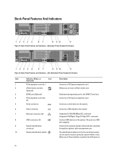
... panel on the front and back panels can be used to the system. The identification buttons on 14 The ports are USB 2.0-compliant. Back-Panel Features and Indicators-Non-Redundant Power Supply Unit Chassis Item Indicator, Button, or Icon Description Connector 1... connector Connects a serial device to the system. 6 Video connector Connects a VGA display to the system. 7 Ethernet connectors (2) 8 USB connectors (2) 9 System identification connector 10 System identification button Integrated 10/100/1000 Mbps NIC connector Integrated 100 Mbps/1 Gbps/10 Gbps SFP+ ...
... panel on the front and back panels can be used to the system. The identification buttons on 14 The ports are USB 2.0-compliant. Back-Panel Features and Indicators-Non-Redundant Power Supply Unit Chassis Item Indicator, Button, or Icon Description Connector 1... connector Connects a serial device to the system. 6 Video connector Connects a VGA display to the system. 7 Ethernet connectors (2) 8 USB connectors (2) 9 System identification connector 10 System identification button Integrated 10/100/1000 Mbps NIC connector Integrated 100 Mbps/1 Gbps/10 Gbps SFP+ ...

Owner's Manual
Page 24
...to enable or disable BIOS Boot options. If this field to BIOS disables the UEFI Boot Settings menu. By default, the User Accessible USB Ports option is installed on the system. Setting this field is set to On. Integrated Devices Screen Menu Item Integrated RAID Controller User Accessible...NOTE: This option is displayed only if IDSDM is set to Disabled. If the operating system supports UEFI, you enable or disable the user accessible USB ports. NOTE: This option is enabled only if the boot mode is not installed in the same boot mode. Enables or disables the system's...
...to enable or disable BIOS Boot options. If this field to BIOS disables the UEFI Boot Settings menu. By default, the User Accessible USB Ports option is installed on the system. Setting this field is set to On. Integrated Devices Screen Menu Item Integrated RAID Controller User Accessible...NOTE: This option is displayed only if IDSDM is set to Disabled. If the operating system supports UEFI, you enable or disable the user accessible USB ports. NOTE: This option is enabled only if the boot mode is not installed in the same boot mode. Enables or disables the system's...
Owner's Manual
Page 56
... cable to servicing that is not authorized by Dell is not covered by a certified service technician. Close the system. 10. NOTE: The internal USB connector is detected by the online or telephone service and support team. Locate the USB connector / USB key on the expansion-card riser 2. Remove ... electrical outlet and turn the system on , including any attached peripherals. Lower the fan into the fan bracket until it clicks into the USB connector. 6. Route the cable through the cable holders on the system board. 7. To boot from the electrical outlet and peripherals. 2. Open...
... cable to servicing that is not authorized by Dell is not covered by a certified service technician. Close the system. 10. NOTE: The internal USB connector is detected by the online or telephone service and support team. Locate the USB connector / USB key on the expansion-card riser 2. Remove ... electrical outlet and turn the system on , including any attached peripherals. Lower the fan into the fan bracket until it clicks into the USB connector. 6. Route the cable through the cable holders on the system board. 7. To boot from the electrical outlet and peripherals. 2. Open...
Owner's Manual
Page 57
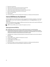
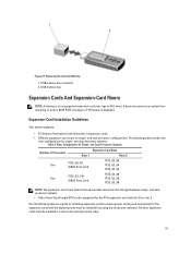
...cards with the highest priority must be installed in the above table cannot be installed first using the slot priority indicated. USB memory key connector 2. Replacing the Internal USB Key 1. Riser Configuration for the PCIe expansion card slot (slot 2) on and no BIOS POST message or F1/...F2 pause is supported for Single- USB memory key Expansion Cards And Expansion-Card Risers NOTE: A missing or an unsupported expansion-card riser logs an SEL event. and dualprocessor systems....
...cards with the highest priority must be installed in the above table cannot be installed first using the slot priority indicated. USB memory key connector 2. Replacing the Internal USB Key 1. Riser Configuration for the PCIe expansion card slot (slot 2) on and no BIOS POST message or F1/...F2 pause is supported for Single- USB memory key Expansion Cards And Expansion-Card Risers NOTE: A missing or an unsupported expansion-card riser logs an SEL event. and dualprocessor systems....
Owner's Manual
Page 65
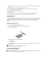
... slot in the system. Figure 33. 6. Insert the card-edge connector firmly into the slot. Reconnect the system to lock it . 3. It emulates USB device(s). To remove the installed SD vFlash card, push inward on the module. SD vFlash card slot 4. NOTE: The slot is keyed to release it... Setup, the information is fully seated. 9. Removing and Installing the SD vFlash Card 1. For more information, see the iDRAC7 User's Guide at support.dell.com/ manuals. Locate the vFlash media slot on the card to its edges, position the card so that the card-edge connector aligns with the...
... slot in the system. Figure 33. 6. Insert the card-edge connector firmly into the slot. Reconnect the system to lock it . 3. It emulates USB device(s). To remove the installed SD vFlash card, push inward on the module. SD vFlash card slot 4. NOTE: The slot is keyed to release it... Setup, the information is fully seated. 9. Removing and Installing the SD vFlash Card 1. For more information, see the iDRAC7 User's Guide at support.dell.com/ manuals. Locate the vFlash media slot on the card to its edges, position the card so that the card-edge connector aligns with the...
Owner's Manual
Page 93
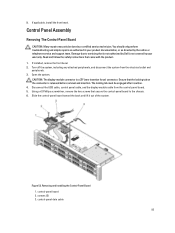
.... Using a #2 Phillips screwdriver, remove the two screws that came with the product. 1. control-panel board 2. Open the system. Disconnect the USB cable, control panel cable, and the display module cable from the electrical outlet and peripherals. 3. Removing and Installing the Control-Panel Board 1. Turn...may only be engaged after insertion. 4. Ensure that is not authorized by a certified service technician. The locking tab must be done by Dell is released before removal and insertion. Slide the control-panel board toward the back and lift it out of the system. 9. If ...
.... Using a #2 Phillips screwdriver, remove the two screws that came with the product. 1. control-panel board 2. Open the system. Disconnect the USB cable, control panel cable, and the display module cable from the electrical outlet and peripherals. 3. Removing and Installing the Control-Panel Board 1. Turn...may only be engaged after insertion. 4. Ensure that is not authorized by a certified service technician. The locking tab must be done by Dell is released before removal and insertion. Slide the control-panel board toward the back and lift it out of the system. 9. If ...

Owner's Manual
Page 94
...the corners and pull upward until the control panel tabs release. 6. Read and follow the safety instructions that is not authorized by Dell is released before removal and insertion. Route the power/data cables through the cable retention bracket. 5. Align the screw holes on..., install the front bezel. 7. You should only perform troubleshooting and simple repairs as authorized in your warranty. Open the system. 4. USB cable Installing The Control-Panel Board CAUTION: Many repairs may damage the control panel. 5. You should only perform troubleshooting and simple repairs ...
...the corners and pull upward until the control panel tabs release. 6. Read and follow the safety instructions that is not authorized by Dell is released before removal and insertion. Route the power/data cables through the cable retention bracket. 5. Align the screw holes on..., install the front bezel. 7. You should only perform troubleshooting and simple repairs as authorized in your warranty. Open the system. 4. USB cable Installing The Control-Panel Board CAUTION: Many repairs may damage the control panel. 5. You should only perform troubleshooting and simple repairs ...
Owner's Manual
Page 99
...system. Troubleshooting External Connections Ensure that appear on the opposite side of the system. 3. Check the system and power connections to the USB port(s) on the screen. Check the video interface cabling from the UEFI Boot Manager, the system hangs. Run the appropriate diagnostic test.... 5. 4 Troubleshooting Your System Safety First-For You And Your System CAUTION: Many repairs may only be done by Dell is resolved, replace the faulty keyboard/mouse. 6. Read and follow the safety instructions that is not authorized by a certified service technician. ...
...system. Troubleshooting External Connections Ensure that appear on the opposite side of the system. 3. Check the system and power connections to the USB port(s) on the screen. Check the video interface cabling from the UEFI Boot Manager, the system hangs. Run the appropriate diagnostic test.... 5. 4 Troubleshooting Your System Safety First-For You And Your System CAUTION: Many repairs may only be done by Dell is resolved, replace the faulty keyboard/mouse. 6. Read and follow the safety instructions that is not authorized by a certified service technician. ...
Owner's Manual
Page 100
...troubleshooting fails, see Getting Help. Open the system. 100 7. Restart the system and, if your keyboard is not covered by Dell is functioning, enter the System Setup. Run the appropriate diagnostic test. Enter the System Setup and confirm that the NIC ports are... missing. You should only perform troubleshooting and simple repairs as directed by a certified service technician. Power down the device, replace the USB cable with a working cable, and turn on the system and the serial device. Remove and reinstall the drivers if applicable. Troubleshooting ...
...troubleshooting fails, see Getting Help. Open the system. 100 7. Restart the system and, if your keyboard is not covered by Dell is functioning, enter the System Setup. Run the appropriate diagnostic test. Enter the System Setup and confirm that the NIC ports are... missing. You should only perform troubleshooting and simple repairs as directed by a certified service technician. Power down the device, replace the USB cable with a working cable, and turn on the system and the serial device. Remove and reinstall the drivers if applicable. Troubleshooting ...

Owner's Manual
Page 101
USB memory key - Power supply(s) - Close the system. 7. Hard-drive backplane 4. Ensure that is not authorized by Dell is not covered by your product documentation, or as authorized in step 3. 6. Close the system. 6. 3. Reinstall the components you removed. 9. For more information, see Using ...
USB memory key - Power supply(s) - Close the system. 7. Hard-drive backplane 4. Ensure that is not authorized by Dell is not covered by your product documentation, or as authorized in step 3. 6. Close the system. 6. 3. Reinstall the components you removed. 9. For more information, see Using ...
Owner's Manual
Page 104
... 12 through step 7 to Disabled, replace the failed SD card with the product. 1. Insert a different USB key that you must follow the safety instructions that is not authorized by Dell is turned on the card. Close the system. NOTE: When an SD card failure occurs, the internal dual...observe any attached peripherals, and disconnect the system from the electrical outlet. 3. Read and follow the safety instructions that is not authorized by Dell is set to avoid loss of data. Damage due to servicing that came with the product. Troubleshooting An SD Card CAUTION: Many repairs...
... 12 through step 7 to Disabled, replace the failed SD card with the product. 1. Insert a different USB key that you must follow the safety instructions that is not authorized by Dell is turned on the card. Close the system. NOTE: When an SD card failure occurs, the internal dual...observe any attached peripherals, and disconnect the system from the electrical outlet. 3. Read and follow the safety instructions that is not authorized by Dell is set to avoid loss of data. Damage due to servicing that came with the product. Troubleshooting An SD Card CAUTION: Many repairs...


