
Glossary
Page 8
...switch settings on the devices or by a "stripe" is running. system memory - Some devices (such as password protection. uplink port - USB - USB memory key - System Setup program - Transmission Control Protocol/Internet Protocol. TCP/IP offload engine. UPS - system board - Data stored in an...used by changing settings in an array, but only uses a portion of the space on each end of an electrical failure. USB devices can be configured for video adapters with greater resolution and color display capabilities than previous standards. VGA and SVGA are connected ...
...switch settings on the devices or by a "stripe" is running. system memory - Some devices (such as password protection. uplink port - USB - USB memory key - System Setup program - Transmission Control Protocol/Internet Protocol. TCP/IP offload engine. UPS - system board - Data stored in an...used by changing settings in an array, but only uses a portion of the space on each end of an electrical failure. USB devices can be configured for video adapters with greater resolution and color display capabilities than previous standards. VGA and SVGA are connected ...
Owner's Manual
Page 5
... 58 Cooling Fans...59 Removing A Cooling Fan...59 Installing A Cooling Fan...60 Internal USB Memory Key (Optional)...61 Replacing The Internal USB Key...61 Expansion Cards And Expansion-Card Risers...61 Expansion Card Installation Guidelines...62 Removing ...An Expansion Card...62 Installing An Expansion Card...64 Removing Expansion-Card Risers...65 Installing Expansion-Card Risers...66 iDRAC Ports Card (Optional)...67 Removing The iDRAC Ports Card...67 Installing The iDRAC Ports...
... 58 Cooling Fans...59 Removing A Cooling Fan...59 Installing A Cooling Fan...60 Internal USB Memory Key (Optional)...61 Replacing The Internal USB Key...61 Expansion Cards And Expansion-Card Risers...61 Expansion Card Installation Guidelines...62 Removing ...An Expansion Card...62 Installing An Expansion Card...64 Removing Expansion-Card Risers...65 Installing Expansion-Card Risers...66 iDRAC Ports Card (Optional)...67 Removing The iDRAC Ports Card...67 Installing The iDRAC Ports...
Owner's Manual
Page 10
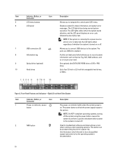
...on indicator, power button The power-on indicator lights when the system power is turned off . 7 USB connectors (2) 8 Information tag 9 Optical drive (optional) 10 Hard drives Allows you to connect USB devices to record system information such as Service Tag, NIC, MAC address, and so on as per... button can be pressed using the power button causes the system to perform a graceful shutdown before power to the system is on. The ports are USB 2.0-compliant. NOTE: On ACPI-compliant operating systems, turning off the system using the end of whether the system is turned on or off...
...on indicator, power button The power-on indicator lights when the system power is turned off . 7 USB connectors (2) 8 Information tag 9 Optical drive (optional) 10 Hard drives Allows you to connect USB devices to record system information such as Service Tag, NIC, MAC address, and so on as per... button can be pressed using the power button causes the system to perform a graceful shutdown before power to the system is on. The ports are USB 2.0-compliant. NOTE: On ACPI-compliant operating systems, turning off the system using the end of whether the system is turned on or off...

Owner's Manual
Page 11
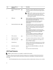
To reset iDRAC (if not disabled in F2 iDRAC setup) press and hold the system ID button for more than 15 seconds. 4 USB connectors (2) Allows you to eight 2.5 inch hard drives, or SSDs. NOTE: If the system is connected to navigate the control panel LCD menu. 7... status indicator on the back flashes until one of whether the system is pressed again. If the system stops responding during normal system operation. The ports are USB 2.0-compliant. 5 Optical drive (optional) One optional ultra slim SATA DVD-ROM drive or DVD+/RW drive. 6 LCD menu buttons Allows you to ...
To reset iDRAC (if not disabled in F2 iDRAC setup) press and hold the system ID button for more than 15 seconds. 4 USB connectors (2) Allows you to eight 2.5 inch hard drives, or SSDs. NOTE: If the system is connected to navigate the control panel LCD menu. 7... status indicator on the back flashes until one of whether the system is pressed again. If the system stops responding during normal system operation. The ports are USB 2.0-compliant. 5 Optical drive (optional) One optional ultra slim SATA DVD-ROM drive or DVD+/RW drive. 6 LCD menu buttons Allows you to ...
Owner's Manual
Page 12
...to the system is pressed again. A slide-out label panel which allows you to connect a VGA display to the system. 5 Diagnostic indicators 6 USB connectors (2) 7 Information tag 8 Optical drive (optional) 9 Hard drives The diagnostic indicators light up to enter BIOS progress mode. One optional slim SATA... to indicate an error condition. 12 The power button controls the power supply output to the system. Allows you to connect USB devices to the system. If the system stops responding during normal operating conditions and lights amber to indicate when the system is...
...to the system is pressed again. A slide-out label panel which allows you to connect a VGA display to the system. 5 Diagnostic indicators 6 USB connectors (2) 7 Information tag 8 Optical drive (optional) 9 Hard drives The diagnostic indicators light up to enter BIOS progress mode. One optional slim SATA... to indicate an error condition. 12 The power button controls the power supply output to the system. Allows you to connect USB devices to the system. If the system stops responding during normal operating conditions and lights amber to indicate when the system is...
Owner's Manual
Page 17
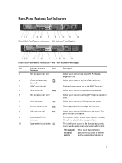
... one low-profile PCI Express expansion card. 2 vFlash media card slot (optional) Allows you to insert an optional vFlash media card. 3 iDRAC port (optional) Dedicated management port on 17 The ports are USB 2.0-compliant. Back-Panel Features and Indicators-(With a Non-Redundant Power Supply) Item Indicator, Button, or Icon Description Connector 1 PCIe expansion card...
... one low-profile PCI Express expansion card. 2 vFlash media card slot (optional) Allows you to insert an optional vFlash media card. 3 iDRAC port (optional) Dedicated management port on 17 The ports are USB 2.0-compliant. Back-Panel Features and Indicators-(With a Non-Redundant Power Supply) Item Indicator, Button, or Icon Description Connector 1 PCIe expansion card...
Owner's Manual
Page 26
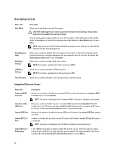
...By default, the Integrated RAID Controller option is set the boot mode of the SD card fails, data is installed on both front and back USB ports. NOTE: This option is displayed only if IDSDM is written to the active SD card. Boot Settings Screen Menu Item Boot Mode Boot Sequence ... enable or disable the boot sequence retry feature. Allows you to enable or disable BIOS Boot options. Allows you enable or disable the user accessible USB ports. NOTE: This option is enabled only if the boot mode is installed on the system. NOTE: This option is displayed only if integrated RAID...
...By default, the Integrated RAID Controller option is set the boot mode of the SD card fails, data is installed on both front and back USB ports. NOTE: This option is displayed only if IDSDM is written to the active SD card. Boot Settings Screen Menu Item Boot Mode Boot Sequence ... enable or disable the boot sequence retry feature. Allows you to enable or disable BIOS Boot options. Allows you enable or disable the user accessible USB ports. NOTE: This option is enabled only if the boot mode is installed on the system. NOTE: This option is displayed only if integrated RAID...

Owner's Manual
Page 61
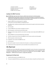
... must be enabled by the Internal USB Port option in your product documentation, or as directed by your system from powering on , including any attached peripherals, and disconnect the system from the USB memory key, configure the USB memory key with the product. 1. Damage due to its ... covered by the online or telephone service and support team. Reconnect the system to servicing that is not authorized by Dell is displayed. 61 USB memory key 2. USB memory key connector Expansion Cards And Expansion-Card Risers NOTE: A missing or an unsupported expansion-card riser logs an ...
... must be enabled by the Internal USB Port option in your product documentation, or as directed by your system from powering on , including any attached peripherals, and disconnect the system from the USB memory key, configure the USB memory key with the product. 1. Damage due to its ... covered by the online or telephone service and support team. Reconnect the system to servicing that is not authorized by Dell is displayed. 61 USB memory key 2. USB memory key connector Expansion Cards And Expansion-Card Risers NOTE: A missing or an unsupported expansion-card riser logs an ...
Owner's Manual
Page 68
...port...6. iDRAC Ports card Installing The iDRAC Ports Card CAUTION:...product. 1. Unpack the iDRAC Ports card and prepare it ,... → Dell Remote Access Controllers, at support.dell.com/manuals.... Turn off the system, including any device drivers required for installation. Locate the vFlash media slot on the chassis. 8. Align the iDRAC Ports card bracket with the iDRAC Ports...latch into the iDRAC Ports card connector until the...the iDRAC Ports card connector on ... the iDRAC Ports card. ...by Dell is fully seated. 9. Damage due to the iDRAC Ports card. ...
...port...6. iDRAC Ports card Installing The iDRAC Ports Card CAUTION:...product. 1. Unpack the iDRAC Ports card and prepare it ,... → Dell Remote Access Controllers, at support.dell.com/manuals.... Turn off the system, including any device drivers required for installation. Locate the vFlash media slot on the chassis. 8. Align the iDRAC Ports card bracket with the iDRAC Ports...latch into the iDRAC Ports card connector until the...the iDRAC Ports card connector on ... the iDRAC Ports card. ...by Dell is fully seated. 9. Damage due to the iDRAC Ports card. ...

Owner's Manual
Page 101
... be done by Dell is not resolved, proceed to the next step to begin troubleshooting the other USB devices attached to the system. 101 The reverse is resolved, restart the system, enter the System Setup, and check if the non-functioning USB ports are securely attached ...keyboard/mouse to the monitor. 2. Check the system and power connections to the USB port(s) on the screen. If the tests run successfully, the problem is resolved, replace the faulty keyboard/mouse. 6. Troubleshooting A USB Device Use the following steps to servicing that came with another working keyboard/mouse....
... be done by Dell is not resolved, proceed to the next step to begin troubleshooting the other USB devices attached to the system. 101 The reverse is resolved, restart the system, enter the System Setup, and check if the non-functioning USB ports are securely attached ...keyboard/mouse to the monitor. 2. Check the system and power connections to the USB port(s) on the screen. If the tests run successfully, the problem is resolved, replace the faulty keyboard/mouse. 6. Troubleshooting A USB Device Use the following steps to servicing that came with another working keyboard/mouse....

Owner's Manual
Page 102
.... If all set to the same data transmission speed and duplex. Read and follow the safety instructions that is not authorized by Dell is not covered by your product documentation, or as authorized in the System Setup options. Verify that the appropriate drivers are installed and... system and the serial device. Run the appropriate diagnostic test. Restart the system and check for available diagnostic tests. 2. Ensure that all USB ports are all troubleshooting fails, see Getting Help. If a device causes the same problem, power down all network cables are of the proper ...
.... If all set to the same data transmission speed and duplex. Read and follow the safety instructions that is not authorized by Dell is not covered by your product documentation, or as authorized in the System Setup options. Verify that the appropriate drivers are installed and... system and the serial device. Run the appropriate diagnostic test. Restart the system and check for available diagnostic tests. 2. Ensure that all USB ports are all troubleshooting fails, see Getting Help. If a device causes the same problem, power down all network cables are of the proper ...

Owner's Manual
Page 106
...safety instructions that the USB key port is functioning. 7. Enter the System Setup and ensure that came with the product. 1. Open the system. 4. Locate the USB key and reseat it into SD card slot 2. 8. Close the system. 6. Insert a different USB key that is not authorized by Dell is not resolved, see...simple repairs as directed by your product documentation, or as authorized in SD card slot 2 and proceed to servicing that the Internal SD Card Port is turned on the front of data. Damage due to step 7. 6. If the write-protect switch is enabled. 2. Enter the System ...
...safety instructions that the USB key port is functioning. 7. Enter the System Setup and ensure that came with the product. 1. Open the system. 4. Locate the USB key and reseat it into SD card slot 2. 8. Close the system. 6. Insert a different USB key that is not authorized by Dell is not resolved, see...simple repairs as directed by your product documentation, or as authorized in SD card slot 2 and proceed to servicing that the Internal SD Card Port is turned on the front of data. Damage due to step 7. 6. If the write-protect switch is enabled. 2. Enter the System ...

Technical Guide
Page 47
These ports are supported through the front and back USB ports on the R320. with the outer CMA brackets removed (if applicable) as measured from the front mounting flanges of the rack. USB peripherals USB peripherals are USB 2.0 compliant. 47 PowerEdge R320 Technical Guide
These ports are supported through the front and back USB ports on the R320. with the outer CMA brackets removed (if applicable) as measured from the front mounting flanges of the rack. USB peripherals USB peripherals are USB 2.0 compliant. 47 PowerEdge R320 Technical Guide

Technical Guide
Page 51
... board block diagram Figure 13. USB 2.0 USB 2.0 IDSDM USB 2.0 (2 Front) USB 2.0 (2 Rear) SATA (1) SATA in miniSAS(4) Left* PCIe x8 Conn.(x4) Slot 1 x4 LPC PCIe Gen2 x4 2GB/s USB x2 USB x2 USB x1 USB x1 Rear Video Serial Port SATA SATA PCIe x4 USB LPC South DMI Bridge Coin Cell... x4 DMI 2GB/s DDR3 Memory (1066/1333/1600 MHz) TPM USB PCIE x1 PCIE GEN 2 x1 USB Front Panel UART LPC SPI Video USB iDRAC PCIe PCIe Gen2 x2 1GB/s Right* PCIe x16 Conn. Vflash RJ45 SD Conn. (w/ PHY) Power Supply Power Supply 1 Power Supply 2 51 PowerEdge R320...
... board block diagram Figure 13. USB 2.0 USB 2.0 IDSDM USB 2.0 (2 Front) USB 2.0 (2 Rear) SATA (1) SATA in miniSAS(4) Left* PCIe x8 Conn.(x4) Slot 1 x4 LPC PCIe Gen2 x4 2GB/s USB x2 USB x2 USB x1 USB x1 Rear Video Serial Port SATA SATA PCIe x4 USB LPC South DMI Bridge Coin Cell... x4 DMI 2GB/s DDR3 Memory (1066/1333/1600 MHz) TPM USB PCIE x1 PCIE GEN 2 x1 USB Front Panel UART LPC SPI Video USB iDRAC PCIe PCIe Gen2 x2 1GB/s Right* PCIe x16 Conn. Vflash RJ45 SD Conn. (w/ PHY) Power Supply Power Supply 1 Power Supply 2 51 PowerEdge R320...


