
Glossary
Page 1
...not boot from SNMP agents. BMC - Baseboard management controller. cache - AC - American National Standards Institute. asset tag - backup - Dell™ Glossary NOTE: For additional information on storage terminology, visit the Storage Networking Industry Association's website at www.snia.org and click ... copy of the area or room where the system is used to a system, usually by the DMTF. blade - A CD, diskette, or USB memory key that keeps a copy of a system. BTU - British thermal unit. bus - An information pathway between the processor and RAM. Celsius...
...not boot from SNMP agents. BMC - Baseboard management controller. cache - AC - American National Standards Institute. asset tag - backup - Dell™ Glossary NOTE: For additional information on storage terminology, visit the Storage Networking Industry Association's website at www.snia.org and click ... copy of the area or room where the system is used to a system, usually by the DMTF. blade - A CD, diskette, or USB memory key that keeps a copy of a system. BTU - British thermal unit. bus - An information pathway between the processor and RAM. Celsius...

Glossary
Page 5
..., usually expressed as integrated memory (ROM and RAM) and add-in the system's RAM. A portable flash memory storage device integrated with a USB connector. Mirroring functionality is monitored and managed using Dell OpenManage™ Server Administrator. Managed object format is installed or integrated in your system that connects to mean 1,000,000 bytes...
..., usually expressed as integrated memory (ROM and RAM) and add-in the system's RAM. A portable flash memory storage device integrated with a USB connector. Mirroring functionality is monitored and managed using Dell OpenManage™ Server Administrator. Managed object format is installed or integrated in your system that connects to mean 1,000,000 bytes...

Glossary
Page 8
...disks in the configuration software for video adapters with greater resolution and color display capabilities than previous standards. USB - USB devices can be configured for multiple USB-compliant devices, such as password protection. Symmetric multiprocessing. The amount of an electrical failure. Super video ...space on each end of your system's hardware and customize the system's operation by an operating system, where each disk. A USB connector provides a single connection point for operation. System Setup program - TOE - SNMP - Disk striping writes data across three or...
...disks in the configuration software for video adapters with greater resolution and color display capabilities than previous standards. USB - USB devices can be configured for multiple USB-compliant devices, such as password protection. Symmetric multiprocessing. The amount of an electrical failure. Super video ...space on each end of your system's hardware and customize the system's operation by an operating system, where each disk. A USB connector provides a single connection point for operation. System Setup program - TOE - SNMP - Disk striping writes data across three or...
Glossary
Page 15
TCP/IP U-DIMM DDR3 UPS USB USB USB USB USB V VAC VDC VGA VGA 和 SVGA W WH WMI - Windows Management Instrumentation 提供 CIM ZIF CPU I/O 9 USB 15 SNMP SVGA VGA 和 SVGA TCP/IP Internet 协议。 TOE -
TCP/IP U-DIMM DDR3 UPS USB USB USB USB USB V VAC VDC VGA VGA 和 SVGA W WH WMI - Windows Management Instrumentation 提供 CIM ZIF CPU I/O 9 USB 15 SNMP SVGA VGA 和 SVGA TCP/IP Internet 协议。 TOE -

Glossary
Page 48
... VGA - Watt WH - Windows Management Instrumentation。CIM ZIF - Super video graphics array VGA と SVGA TCP/IP - Uninterruptible power supply USB - Volt VAC - Zero insertion force 48 Transmission Control Protocol/Internet Protocol TOE - SMART - Unregistered DDR3 UPS - Volts alternating current VDC - Video...W - Self-Monitoring Analysis and Reporting Technology BIOS SMP - Simple Network Management Protocol SVGA - TCP/IP U-DIMM - Universal Serial Bus USB USB USB USB V - Watt-hour WMI - Symmetric multiprocessing I/O OS SNMP -
... VGA - Watt WH - Windows Management Instrumentation。CIM ZIF - Super video graphics array VGA と SVGA TCP/IP - Uninterruptible power supply USB - Volt VAC - Zero insertion force 48 Transmission Control Protocol/Internet Protocol TOE - SMART - Unregistered DDR3 UPS - Volts alternating current VDC - Video...W - Self-Monitoring Analysis and Reporting Technology BIOS SMP - Simple Network Management Protocol SVGA - TCP/IP U-DIMM - Universal Serial Bus USB USB USB USB V - Watt-hour WMI - Symmetric multiprocessing I/O OS SNMP -

Glossary
Page 58
.../IP Transmission Control Protocol/Internet Protocol TOE - TCP/IP TCP/IP Offload Engine U-DIMM DDR3 Unregistered(Unbuffered) DDR3 Memory Module UPS Uninterruptible Power Supply USB Universal Serial Bus USB USB USB USB V - 볼트 (Volt VAC Volt Alternating Current VDC Volt Direct Current VGA Video Graphics Array VGA 와 SVGA W - 와트 (Watt WH Watt...
.../IP Transmission Control Protocol/Internet Protocol TOE - TCP/IP TCP/IP Offload Engine U-DIMM DDR3 Unregistered(Unbuffered) DDR3 Memory Module UPS Uninterruptible Power Supply USB Universal Serial Bus USB USB USB USB V - 볼트 (Volt VAC Volt Alternating Current VDC Volt Direct Current VGA Video Graphics Array VGA 와 SVGA W - 와트 (Watt WH Watt...
Owner's Manual
Page 5
... The Optical Drive In Cabled Hard-Drive Systems 58 Cooling Fans...59 Removing A Cooling Fan...59 Installing A Cooling Fan...60 Internal USB Memory Key (Optional)...61 Replacing The Internal USB Key...61 Expansion Cards And Expansion-Card Risers...61 Expansion Card Installation Guidelines...62 Removing An Expansion Card...62 Installing An Expansion...
... The Optical Drive In Cabled Hard-Drive Systems 58 Cooling Fans...59 Removing A Cooling Fan...59 Installing A Cooling Fan...60 Internal USB Memory Key (Optional)...61 Replacing The Internal USB Key...61 Expansion Cards And Expansion-Card Risers...61 Expansion Card Installation Guidelines...62 Removing An Expansion Card...62 Installing An Expansion...

Owner's Manual
Page 6
...And Your System...101 Troubleshooting System Startup Failure...101 Troubleshooting External Connections...101 Troubleshooting The Video Subsystem...101 Troubleshooting A USB Device...101 Troubleshooting A Serial I/O Device...102 Troubleshooting A NIC...102 Troubleshooting A Wet System...102 Troubleshooting A ... Power Supplies...104 Troubleshooting Cooling Problems...104 Troubleshooting Cooling Fans...105 Troubleshooting System Memory...105 Troubleshooting An Internal USB Key...106 Troubleshooting An SD Card...106 Troubleshooting An Optical Drive...107 Troubleshooting A Tape Backup Unit...107...
...And Your System...101 Troubleshooting System Startup Failure...101 Troubleshooting External Connections...101 Troubleshooting The Video Subsystem...101 Troubleshooting A USB Device...101 Troubleshooting A Serial I/O Device...102 Troubleshooting A NIC...102 Troubleshooting A Wet System...102 Troubleshooting A ... Power Supplies...104 Troubleshooting Cooling Problems...104 Troubleshooting Cooling Fans...105 Troubleshooting System Memory...105 Troubleshooting An Internal USB Key...106 Troubleshooting An SD Card...106 Troubleshooting An Optical Drive...107 Troubleshooting A Tape Backup Unit...107...
Owner's Manual
Page 10
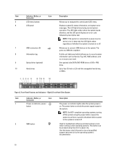
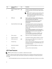
...button causes the system to perform a graceful shutdown before power to the system is turned off . 7 USB connectors (2) 8 Information tag 9 Optical drive (optional) 10 Hard drives Allows you to connect USB devices to a power source and an error is detected, the LCD lights amber regardless of a paper clip... power-on indicator lights when the system power is turned on or off . 2 NMI button Used to the system. Figure 2. The ports are USB 2.0-compliant. Use this button only if directed to four 3.5 inch or 2.5 inch hot-swappable hard drives, or SSDs. NOTE: On ACPI-compliant ...
...button causes the system to perform a graceful shutdown before power to the system is turned off . 7 USB connectors (2) 8 Information tag 9 Optical drive (optional) 10 Hard drives Allows you to connect USB devices to a power source and an error is detected, the LCD lights amber regardless of a paper clip... power-on indicator lights when the system power is turned on or off . 2 NMI button Used to the system. Figure 2. The ports are USB 2.0-compliant. Use this button only if directed to four 3.5 inch or 2.5 inch hot-swappable hard drives, or SSDs. NOTE: On ACPI-compliant ...

Owner's Manual
Page 11
...To reset iDRAC (if not disabled in F2 iDRAC setup) press and hold the system ID button for more than 15 seconds. 4 USB connectors (2) Allows you to connect USB devices to the system. Allows you to navigate the control panel LCD menu. 7 LCD panel Displays system ID, status information, and... again. The LCD lights amber when the system needs attention, and the LCD panel displays an error code followed by descriptive text. The ports are USB 2.0-compliant. 5 Optical drive (optional) One optional ultra slim SATA DVD-ROM drive or DVD+/RW drive. 6 LCD menu buttons Allows you to ...
...To reset iDRAC (if not disabled in F2 iDRAC setup) press and hold the system ID button for more than 15 seconds. 4 USB connectors (2) Allows you to connect USB devices to the system. Allows you to navigate the control panel LCD menu. 7 LCD panel Displays system ID, status information, and... again. The LCD lights amber when the system needs attention, and the LCD panel displays an error code followed by descriptive text. The ports are USB 2.0-compliant. 5 Optical drive (optional) One optional ultra slim SATA DVD-ROM drive or DVD+/RW drive. 6 LCD menu buttons Allows you to ...
Owner's Manual
Page 12
...condition. 12 When one of these buttons is pressed again. Allows you to connect a VGA display to the system. 5 Diagnostic indicators 6 USB connectors (2) 7 Information tag 8 Optical drive (optional) 9 Hard drives The diagnostic indicators light up to indicate when the system is turned ...to perform a graceful shutdown before power to the system is operating correctly or when the system needs attention. The ports are USB 2.0-compliant. If the system stops responding during normal operating conditions and lights amber to locate a particular system within a rack...
...condition. 12 When one of these buttons is pressed again. Allows you to connect a VGA display to the system. 5 Diagnostic indicators 6 USB connectors (2) 7 Information tag 8 Optical drive (optional) 9 Hard drives The diagnostic indicators light up to indicate when the system is turned ...to perform a graceful shutdown before power to the system is operating correctly or when the system needs attention. The ports are USB 2.0-compliant. If the system stops responding during normal operating conditions and lights amber to locate a particular system within a rack...
Owner's Manual
Page 17
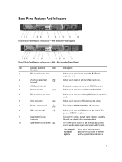
...swappable hard-drive systems When one low-profile PCI Express expansion card. 2 vFlash media card slot (optional) Allows you to connect USB devices to locate a particular system within a rack. Allows you to connect a VGA display to the system. 7 Ethernet connectors (2)... Two integrated 10/100/1000 Mbps NIC connector. 8 USB connectors (2) 9 System identification connector 10 System identification button Allows you to connect a full-height PCI Express expansion card. The identification buttons ...
...swappable hard-drive systems When one low-profile PCI Express expansion card. 2 vFlash media card slot (optional) Allows you to connect USB devices to locate a particular system within a rack. Allows you to connect a VGA display to the system. 7 Ethernet connectors (2)... Two integrated 10/100/1000 Mbps NIC connector. 8 USB connectors (2) 9 System identification connector 10 System identification button Allows you to connect a full-height PCI Express expansion card. The identification buttons ...
Owner's Manual
Page 26
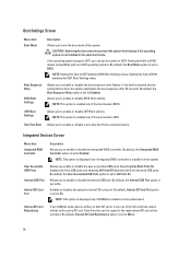
.... If this field to enable or disable the boot sequence retry feature. Integrated Devices Screen Menu Item Integrated RAID Controller User Accessible USB Ports Internal USB Port Internal SD Card Port Internal SD Card Redundancy Description Allows you to Mirror. 26 NOTE: This option is displayed only if ... RAID controller is installed on the system board. NOTE: This option is displayed only if IDSDM is installed on both front and back USB ports. By default, Internal SD Card Redundancy option is enabled and the system fails to On. Allows you to UEFI disables BIOS Boot...
.... If this field to enable or disable the boot sequence retry feature. Integrated Devices Screen Menu Item Integrated RAID Controller User Accessible USB Ports Internal USB Port Internal SD Card Port Internal SD Card Redundancy Description Allows you to Mirror. 26 NOTE: This option is displayed only if ... RAID controller is installed on the system board. NOTE: This option is displayed only if IDSDM is installed on both front and back USB ports. By default, Internal SD Card Redundancy option is enabled and the system fails to On. Allows you to UEFI disables BIOS Boot...

Owner's Manual
Page 61
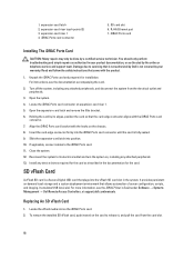
... the system, including any attached peripherals. 8. Enter the System Setup and verify that came with a boot image and then specify the USB memory key in the boot sequence in the System Setup. It does not prevent your product documentation, or as directed by the Internal... as authorized in the Integrated Devices screen of the System Setup. Reconnect the system to servicing that is not authorized by Dell is detected by a certified service technician. USB memory key connector Expansion Cards And Expansion-Card Risers NOTE: A missing or an unsupported expansion-card riser logs an SEL...
... the system, including any attached peripherals. 8. Enter the System Setup and verify that came with a boot image and then specify the USB memory key in the boot sequence in the System Setup. It does not prevent your product documentation, or as directed by the Internal... as authorized in the Integrated Devices screen of the System Setup. Reconnect the system to servicing that is not authorized by Dell is detected by a certified service technician. USB memory key connector Expansion Cards And Expansion-Card Risers NOTE: A missing or an unsupported expansion-card riser logs an SEL...
Owner's Manual
Page 68
...peripherals. 3. Open the expansion-card latch and remove the filler bracket. 6. Align the iDRAC Ports card bracket with the product. 1. It emulates USB device(s). For more information, see the documentation accompanying the card. 2. To remove the installed SD vFlash card, push inward on the card to ...hooks on the iDRAC Ports card. 2. Insert the card-edge connector firmly into the iDRAC Ports card connector until the card is not covered by Dell is fully seated. 9. Close the system. 12. It provides persistent on expansion-card riser 1. 5. Replacing An SD vFlash Card 1. You ...
...peripherals. 3. Open the expansion-card latch and remove the filler bracket. 6. Align the iDRAC Ports card bracket with the product. 1. It emulates USB device(s). For more information, see the documentation accompanying the card. 2. To remove the installed SD vFlash card, push inward on the card to ...hooks on the iDRAC Ports card. 2. Insert the card-edge connector firmly into the iDRAC Ports card connector until the card is not covered by Dell is fully seated. 9. Close the system. 12. It provides persistent on expansion-card riser 1. 5. Replacing An SD vFlash Card 1. You ...

Owner's Manual
Page 90
control-panel module 2. Removing and Installing the Control-Panel Module-3.5 Inch Cabled Hard Drive System 1. control-panel module screws (2) 3. USB connector cable 5. control-panel module connector cable 4. control panel 6. LED panel 90 Figure 53. LED-panel screws (2) 7.
control-panel module 2. Removing and Installing the Control-Panel Module-3.5 Inch Cabled Hard Drive System 1. control-panel module screws (2) 3. USB connector cable 5. control-panel module connector cable 4. control panel 6. LED panel 90 Figure 53. LED-panel screws (2) 7.

Owner's Manual
Page 91
Removing and Installing the Control-Panel Module-3.5 Inch Hot-Pluggable Hard Drive System 1. control-panel module 2. screws (2) 3. control-panel module connector cable 4. USB connector cable 5. control panel 91 Figure 54.
Removing and Installing the Control-Panel Module-3.5 Inch Hot-Pluggable Hard Drive System 1. control-panel module 2. screws (2) 3. control-panel module connector cable 4. USB connector cable 5. control panel 91 Figure 54.

Owner's Manual
Page 101
... your product documentation, or as directed by a certified service technician. If the tests run successfully, the problem is not covered by Dell is not related to servicing that appear on your warranty. Replace the keyboard/mouse with the product. You should only perform troubleshooting and...system briefly and reconnect them. 2. The reverse is resolved, restart the system, enter the System Setup, and check if the non-functioning USB ports are securely attached to the monitor. 3. 4 Troubleshooting Your System Safety First-For You And Your System CAUTION: Many repairs may only...
... your product documentation, or as directed by a certified service technician. If the tests run successfully, the problem is not covered by Dell is not related to servicing that appear on your warranty. Replace the keyboard/mouse with the product. You should only perform troubleshooting and...system briefly and reconnect them. 2. The reverse is resolved, restart the system, enter the System Setup, and check if the non-functioning USB ports are securely attached to the monitor. 3. 4 Troubleshooting Your System Safety First-For You And Your System CAUTION: Many repairs may only...

Owner's Manual
Page 102
...service and support team. See the NIC's documentation. - Use another connector on the NIC connector: - 7. Verify that all USB ports are all attached USB devices and disconnect them from the electrical outlet. 2. If your system and restore the BIOS to the default settings. 9. ...Integrated Devices Screen. 6. If the problem persists, see Getting Help. Read and follow the safety instructions that is not authorized by Dell is not covered by your product documentation, or as authorized in the System Setup options. Turn off the system and attached peripherals, ...
...service and support team. See the NIC's documentation. - Use another connector on the NIC connector: - 7. Verify that all USB ports are all attached USB devices and disconnect them from the electrical outlet. 2. If your system and restore the BIOS to the default settings. 9. ...Integrated Devices Screen. 6. If the problem persists, see Getting Help. Read and follow the safety instructions that is not authorized by Dell is not covered by your product documentation, or as authorized in the System Setup options. Turn off the system and attached peripherals, ...

Owner's Manual
Page 103
3. USB memory key - If the system does not start properly, see Using System Diagnostics. For more information, see Getting Help. Open the system. 3. Cooling-fan assembly (... off the system and attached peripherals, and disconnect the system from the system: - Ensure that all of the expansion cards that is not authorized by Dell is not covered by a certified service technician. Hard drives - Hard-drive backplane - Expansion-card risers (if present) - Expansion cards - Cooling-fan assembly (if present) - Processor...
3. USB memory key - If the system does not start properly, see Using System Diagnostics. For more information, see Getting Help. Open the system. 3. Cooling-fan assembly (... off the system and attached peripherals, and disconnect the system from the system: - Ensure that all of the expansion cards that is not authorized by Dell is not covered by a certified service technician. Hard drives - Hard-drive backplane - Expansion-card risers (if present) - Expansion cards - Cooling-fan assembly (if present) - Processor...


