Getting Started Guide
Page 11
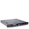
... 2.5-inch cabled SAS or SATA internal drives One optional internal SATA DVD-ROM or DVD+/-RW drive NOTE: DVD devices are data only. Optional external USB DVD-ROM Getting Started With Your System 9
... 2.5-inch cabled SAS or SATA internal drives One optional internal SATA DVD-ROM or DVD+/-RW drive NOTE: DVD devices are data only. Optional external USB DVD-ROM Getting Started With Your System 9

Getting Started Guide
Page 12
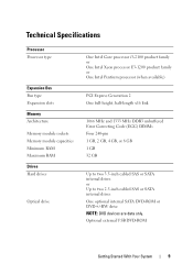
... RJ-45 (for integrated 1 GB NICs) 9-pin, DTE, 16550-compatible Two 4-pin, USB 2.0-compliant 15-pin VGA One 7-pin connector 15-pin VGA Two 4-pin, USB 2.0-compliant Two 4-pin, USB 2.0-compliant Video Video type Video memory Matrox G200, integrated in Winbond WPCM450 8 MB Power AC power supply (per power supply) Wattage 250 W Voltage...
... RJ-45 (for integrated 1 GB NICs) 9-pin, DTE, 16550-compatible Two 4-pin, USB 2.0-compliant 15-pin VGA One 7-pin connector 15-pin VGA Two 4-pin, USB 2.0-compliant Two 4-pin, USB 2.0-compliant Video Video type Video memory Matrox G200, integrated in Winbond WPCM450 8 MB Power AC power supply (per power supply) Wattage 250 W Voltage...

Owner's Manual
Page 5
... Expansion Card 61 Installing an Expansion Card 62 Expansion-Card Riser 63 Removing an Expansion-Card Riser 63 Installing an Expansion-Card Riser 65 Internal USB Memory Key 65 Cooling Shroud 66 Removing the Cooling Shroud 67 Contents 5
... Expansion Card 61 Installing an Expansion Card 62 Expansion-Card Riser 63 Removing an Expansion-Card Riser 63 Installing an Expansion-Card Riser 65 Internal USB Memory Key 65 Cooling Shroud 66 Removing the Cooling Shroud 67 Contents 5
Owner's Manual
Page 7
... System 97 Safety First-For You and Your System 97 Troubleshooting System Startup Failure 97 Troubleshooting External Connections 97 Troubleshooting the Video Subsystem 98 Troubleshooting a USB Device 98 Troubleshooting a Serial I/O Device 99 Troubleshooting a NIC 99 Troubleshooting a Wet System 100 Troubleshooting a Damaged System 101 Troubleshooting the System Battery 102 Troubleshooting Power Supply...
... System 97 Safety First-For You and Your System 97 Troubleshooting System Startup Failure 97 Troubleshooting External Connections 97 Troubleshooting the Video Subsystem 98 Troubleshooting a USB Device 98 Troubleshooting a Serial I/O Device 99 Troubleshooting a NIC 99 Troubleshooting a Wet System 100 Troubleshooting a Damaged System 101 Troubleshooting the System Battery 102 Troubleshooting Power Supply...
Owner's Manual
Page 13
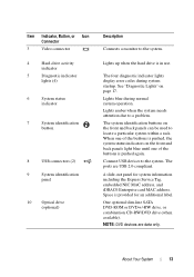
Lights blue during system startup. Connect USB devices to a problem. About Your System 13 Lights amber when the system needs attention due to the system. When one of the ...the system. Item Indicator, Button, or Icon Connector 3 Video connector 4 Hard-drive activity indicator 5 Diagnostic indicator lights (4) 6 System status indicator 7 System identification button 8 USB connectors (2) 9 System identification panel 10 Optical drive (optional) Description Connects a monitor to locate a particular system within a rack. One optional slim-line SATA DVD-ROM ...
Lights blue during system startup. Connect USB devices to a problem. About Your System 13 Lights amber when the system needs attention due to the system. When one of the ...the system. Item Indicator, Button, or Icon Connector 3 Video connector 4 Hard-drive activity indicator 5 Diagnostic indicator lights (4) 6 System status indicator 7 System identification button 8 USB connectors (2) 9 System identification panel 10 Optical drive (optional) Description Connects a monitor to locate a particular system within a rack. One optional slim-line SATA DVD-ROM ...

Owner's Manual
Page 14
... port (optional) 2 VFlash media slot (optional) 3 PCIe expansion card slot 4 Serial connector 5 Video connector 6 eSATA 7 USB connectors (2) 8 Ethernet connectors (2) Description Dedicated management port for the optional iDRAC6 Enterprise card. Connects a serial device to the system. The ports are... USB 2.0-compliant. Embedded 10/100/1000 NIC connectors. 14 About Your System Connects an external SD memory card for the ...
... port (optional) 2 VFlash media slot (optional) 3 PCIe expansion card slot 4 Serial connector 5 Video connector 6 eSATA 7 USB connectors (2) 8 Ethernet connectors (2) Description Dedicated management port for the optional iDRAC6 Enterprise card. Connects a serial device to the system. The ports are... USB 2.0-compliant. Embedded 10/100/1000 NIC connectors. 14 About Your System Connects an external SD memory card for the ...

Owner's Manual
Page 18
Corrective Action Ensure that the optical drive and hard drives are properly connected. See "Troubleshooting a USB Device" on page 104. See "Troubleshooting System Memory" on page 98. See "Getting Help" on page 119. Memory configuration See "Troubleshooting System .... Memory" on page 97 for information on the drives installed in your system. Other failure. Possible system resource configuration error. Possible USB failure. No memory modules detected. Possible system board resource and/or system board hardware failure. See "Troubleshooting Your System" on page 104.
Corrective Action Ensure that the optical drive and hard drives are properly connected. See "Troubleshooting a USB Device" on page 104. See "Troubleshooting System Memory" on page 98. See "Getting Help" on page 119. Memory configuration See "Troubleshooting System .... Memory" on page 97 for information on the drives installed in your system. Other failure. Possible system resource configuration error. Possible USB failure. No memory modules detected. Possible system board resource and/or system board hardware failure. See "Troubleshooting Your System" on page 104.

Owner's Manual
Page 20
... data line failure. No boot device available. Faulty or missing optical drive subsystem, hard drive, or hard-drive subsystem, or no bootable USB key installed. Reboot to the expansion card. If the problem persists, see "Troubleshooting an Expansion Card" on page 109. 20 About Your... Causes Corrective Actions Keyboard cable connector is in a valid configuration. PCIe device BIOS (Option ROM) checksum failure detected during shadowing. Use a bootable USB key, CD, or hard drive. PCI BIOS failed to expansion card loose; See "Using the System Setup Program and Boot Manager" on page ...
... data line failure. No boot device available. Faulty or missing optical drive subsystem, hard drive, or hard-drive subsystem, or no bootable USB key installed. Reboot to the expansion card. If the problem persists, see "Troubleshooting an Expansion Card" on page 109. 20 About Your... Causes Corrective Actions Keyboard cable connector is in a valid configuration. PCIe device BIOS (Option ROM) checksum failure detected during shadowing. Use a bootable USB key, CD, or hard drive. PCI BIOS failed to expansion card loose; See "Using the System Setup Program and Boot Manager" on page ...
Owner's Manual
Page 31
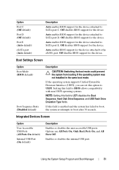
...the same boot mode. Off disables BIOS support for the device attached to UEFI disables the Boot Sequence, Hard-Disk Drive Sequence, and USB Flash Drive Emulation Type fields. If the operating system supports Unified Extensible Firmware Interface (UEFI), you can set this field to SATA ...port C. Enables or disables the internal USB port. Using the System Setup Program and Boot Manager 31 Option Port C (Off default) Port D (Off default) Port E (Auto default) ...
...the same boot mode. Off disables BIOS support for the device attached to UEFI disables the Boot Sequence, Hard-Disk Drive Sequence, and USB Flash Drive Emulation Type fields. If the operating system supports Unified Extensible Firmware Interface (UEFI), you can set this field to SATA ...port C. Enables or disables the internal USB port. Using the System Setup Program and Boot Manager 31 Option Port C (Off default) Port D (Off default) Port E (Auto default) ...
Owner's Manual
Page 38
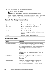
... Option Continue Normal Boot Select Boot Mode Boot Settings System Utilities Description The system attempts to boot to access the System Setup program, System Services (Dell Unified Server Configurator [USC]), Diagnostics, and BIOS-level boot options. 38 Using the System Setup Program and Boot Manager Displays the list of available ...boot options (marked with the first item in the boot order until the USB keyboard is successful or no more boot options are found. Enables you to and highlights the previous field.
... Option Continue Normal Boot Select Boot Mode Boot Settings System Utilities Description The system attempts to boot to access the System Setup program, System Services (Dell Unified Server Configurator [USC]), Diagnostics, and BIOS-level boot options. 38 Using the System Setup Program and Boot Manager Displays the list of available ...boot options (marked with the first item in the boot order until the USB keyboard is successful or no more boot options are found. Enables you to and highlights the previous field.

Owner's Manual
Page 65
...the system board. See "Boot Settings Screen" on page 31. Read and follow the safety instructions that is not authorized by Dell is not covered by Dell is fully seated. 3 If applicable, reinstall the expansion card. CAUTION: Many repairs may only be done by the online or... telephone service and support team. Installing System Components 65 Internal USB Memory Key The USB memory key can be enabled in the System Setup...
...the system board. See "Boot Settings Screen" on page 31. Read and follow the safety instructions that is not authorized by Dell is not covered by Dell is fully seated. 3 If applicable, reinstall the expansion card. CAUTION: Many repairs may only be done by the online or... telephone service and support team. Installing System Components 65 Internal USB Memory Key The USB memory key can be enabled in the System Setup...

Owner's Manual
Page 66
... positioned directly behind the cooling shroud. 66 Installing System Components See "Opening the System" on page 50. 3 Locate the USB connector on , including any attached peripherals, and disconnect the system from the electrical outlet. 2 Open the system. See "Closing...Reconnect the system to these components. Figure 3-10. See Figure 3-20. 4 Insert the USB memory key into the USB connector. 5 Close the system. Removing and Installing a USB Memory Key 1 2 1 USB memory key connector 2 USB memory key Cooling Shroud The cooling shroud covers the processor, heat sink, and memory modules...
... positioned directly behind the cooling shroud. 66 Installing System Components See "Opening the System" on page 50. 3 Locate the USB connector on , including any attached peripherals, and disconnect the system from the electrical outlet. 2 Open the system. See "Closing...Reconnect the system to these components. Figure 3-10. See Figure 3-20. 4 Insert the USB memory key into the USB connector. 5 Close the system. Removing and Installing a USB Memory Key 1 2 1 USB memory key connector 2 USB memory key Cooling Shroud The cooling shroud covers the processor, heat sink, and memory modules...
Owner's Manual
Page 91
See "Opening the System" on page 56. 5 Remove the internal USB key (if present). b Gently work the connector out of the cable connector. 9 Enter the System Setup program to servicing that is not authorized by Dell is operating properly. Damage due to confirm that the battery is not covered by your product documentation...
See "Opening the System" on page 56. 5 Remove the internal USB key (if present). b Gently work the connector out of the cable connector. 9 Enter the System Setup program to servicing that is not authorized by Dell is operating properly. Damage due to confirm that the battery is not covered by your product documentation...
Owner's Manual
Page 92
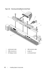
Figure 3-20. Removing and Installing the Control Panel 1 6 2 3 4 5 1 control panel cable 3 USB connectors (4) 5 LED display module 2 USB connector cable 4 screws (4) 6 control panel board 92 Installing System Components
Figure 3-20. Removing and Installing the Control Panel 1 6 2 3 4 5 1 control panel cable 3 USB connectors (4) 5 LED display module 2 USB connector cable 4 screws (4) 6 control panel board 92 Installing System Components
Owner's Manual
Page 93
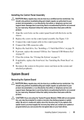
... Board CAUTION: Many repairs may only be prompted to the power source and turn on page 58. 6 If present, replace the internal USB key. Damage due to create and safely store this system board, you must supply the recovery key when you restart your system or program... CAUTION: If you are using the Trusted Program Module (TPM) with the product. See "Internal USB Memory Key" on your warranty. Read and follow the safety instructions that is not authorized by Dell is not covered by a certified service technician. Installing the Control Panel Assembly CAUTION: Many repairs may...
... Board CAUTION: Many repairs may only be prompted to the power source and turn on page 58. 6 If present, replace the internal USB key. Damage due to create and safely store this system board, you must supply the recovery key when you restart your system or program... CAUTION: If you are using the Trusted Program Module (TPM) with the product. See "Internal USB Memory Key" on your warranty. Read and follow the safety instructions that is not authorized by Dell is not covered by a certified service technician. Installing the Control Panel Assembly CAUTION: Many repairs may...
Owner's Manual
Page 96
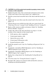
... the connectors on the system board): • SATA interface cable, if applicable • Control panel interface cable • Optical drive power cable • Control panel USB interface cable • System board power cables 10 Install the expansion card, if any attached peripherals. 96 Installing System Components See "Removing a Processor" on page...
... the connectors on the system board): • SATA interface cable, if applicable • Control panel interface cable • Optical drive power cable • Control panel USB interface cable • System board power cables 10 Install the expansion card, if any attached peripherals. 96 Installing System Components See "Removing a Processor" on page...
Owner's Manual
Page 98
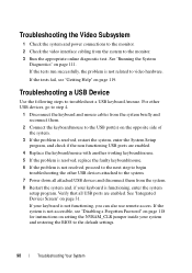
...problem is resolved, replace the faulty keyboard/mouse. 6 If the problem is not resolved, proceed to the next step to begin troubleshooting the other USB devices, go to step 4. 1 Disconnect the keyboard and mouse cables from the system to the monitor. 3 Run the appropriate online diagnostic test....power connections to the monitor. 2 Check the video interface cabling from the system briefly and reconnect them. 2 Connect the keyboard/mouse to the USB port(s) on page 119. If the system is functioning, enter the system setup program. If the tests run successfully, the problem is not ...
...problem is resolved, replace the faulty keyboard/mouse. 6 If the problem is not resolved, proceed to the next step to begin troubleshooting the other USB devices, go to step 4. 1 Disconnect the keyboard and mouse cables from the system to the monitor. 3 Run the appropriate online diagnostic test....power connections to the monitor. 2 Check the video interface cabling from the system briefly and reconnect them. 2 Connect the keyboard/mouse to the USB port(s) on page 119. If the system is functioning, enter the system setup program. If the tests run successfully, the problem is not ...
Owner's Manual
Page 99
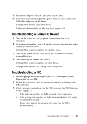
.... • If the link indicator does not light, check all troubleshooting fails, see "Getting Help" on each USB device one at a time. 10 If a device causes the same problem, power down the device, replace the USB cable, and power up the device. See "Running the System Diagnostics" on page 111. 2 Restart the...
.... • If the link indicator does not light, check all troubleshooting fails, see "Getting Help" on each USB device one at a time. 10 If a device causes the same problem, power down the device, replace the USB cable, and power up the device. See "Running the System Diagnostics" on page 111. 2 Restart the...
Owner's Manual
Page 100
... 119. • Change the autonegotiation setting, if possible. • Use another connector on page 47. • Hard drives • USB memory key • NIC hardware key • VFlash media • Expansion card and expansion-card riser 100 Troubleshooting Your System Read and ...follow the safety instructions that is not authorized by Dell is not covered by your product documentation, or as directed by a certified service technician. See "Installing System Components" on the...
... 119. • Change the autonegotiation setting, if possible. • Use another connector on page 47. • Hard drives • USB memory key • NIC hardware key • VFlash media • Expansion card and expansion-card riser 100 Troubleshooting Your System Read and ...follow the safety instructions that is not authorized by Dell is not covered by your product documentation, or as directed by a certified service technician. See "Installing System Components" on the...
Owner's Manual
Page 106
...on the system and attached peripherals and check if the USB key is not covered by your product documentation, or... See "Integrated Devices Screen" on page 50. 4 Locate the USB key and reseat it. Damage due to servicing that is not ... 18 If the memory problem is enabled. See "Internal USB Memory Key" on page 119. Read and follow the...resolved, repeat step 2 and step 3. 8 Insert a different USB key that the USB key port is still indicated, repeat step 12 through step ... and attached peripherals and check if the USB key is functioning. 7 If the problem is not resolved, see...
...on the system and attached peripherals and check if the USB key is not covered by your product documentation, or... See "Integrated Devices Screen" on page 50. 4 Locate the USB key and reseat it. Damage due to servicing that is not ... 18 If the memory problem is enabled. See "Internal USB Memory Key" on page 119. Read and follow the...resolved, repeat step 2 and step 3. 8 Insert a different USB key that the USB key port is still indicated, repeat step 12 through step ... and attached peripherals and check if the USB key is functioning. 7 If the problem is not resolved, see...


