
Information Update
Page 11
..., by default, will not power on. PowerEdge M610 and M710 blades require CMC firmware version 2.0 or later. NOTE: See the latest Dell Chassis Management Controller User's Guide at support.dell.com for complete instructions on how to an M1000e enclosure with your local system. During the update ...process, you add these blades to configure and operate the CMC module. The...
..., by default, will not power on. PowerEdge M610 and M710 blades require CMC firmware version 2.0 or later. NOTE: See the latest Dell Chassis Management Controller User's Guide at support.dell.com for complete instructions on how to an M1000e enclosure with your local system. During the update ...process, you add these blades to configure and operate the CMC module. The...

Information Update
Page 17
Eight ports are external uplink ports, while 16 internal ports provide connectivity to the blades in the enclosure. Mellanox M2401G Infiniband Switch Module 1 2 3 4 5 1 Infiniband ports (8) 3 port activity indicators (8) 5 status/identification indicator 2 port link status indicators (8) 4 module power indicator Information Update 17 Mellanox M2401G Infiniband Switch I/O Module The Mellanox M2401G Infiniband switch I/O module includes 24 4x DDR Infiniband ports. Figure 1-2.
Eight ports are external uplink ports, while 16 internal ports provide connectivity to the blades in the enclosure. Mellanox M2401G Infiniband Switch Module 1 2 3 4 5 1 Infiniband ports (8) 3 port activity indicators (8) 5 status/identification indicator 2 port link status indicators (8) 4 module power indicator Information Update 17 Mellanox M2401G Infiniband Switch I/O Module The Mellanox M2401G Infiniband switch I/O module includes 24 4x DDR Infiniband ports. Figure 1-2.
Getting Started Guide
Page 6
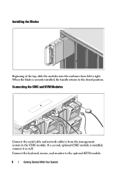
Installing the Blades Beginning at the top, slide the modules into the enclosure from the management system to the CMC module. Connect the keyboard, mouse, and monitor to the closed position. Connecting the CMC and KVM Modules Connect the serial cable and network cable(s) from left to right. If a second, optional CMC module is securely installed, the handle returns to the optional iKVM module. 4 Getting Started With Your System When the blade is installed, connect it as well.
Installing the Blades Beginning at the top, slide the modules into the enclosure from the management system to the CMC module. Connect the keyboard, mouse, and monitor to the closed position. Connecting the CMC and KVM Modules Connect the serial cable and network cable(s) from left to right. If a second, optional CMC module is securely installed, the handle returns to the optional iKVM module. 4 Getting Started With Your System When the blade is installed, connect it as well.
Getting Started Guide
Page 8
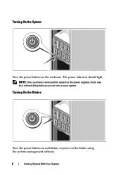
NOTE: Once you have connected the system to the power supplies, there may be a minimal delay before you can turn on the blades using the systems management software. 6 Getting Started With Your System Turning On the Blades Press the power button on each blade, or power on your system. Turning On the System Press the power button on the enclosure. The power indicator should light.
NOTE: Once you have connected the system to the power supplies, there may be a minimal delay before you can turn on the blades using the systems management software. 6 Getting Started With Your System Turning On the Blades Press the power button on each blade, or power on your system. Turning On the System Press the power button on the enclosure. The power indicator should light.
Getting Started Guide
Page 12
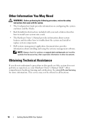
See www.dell.com/training for updates on configuring the system enclosure and the blades. • Rack Installation Instructions included with your rack solution describes how to install your Hardware Owner's Manual. Obtaining Technical Assistance If you do ...WARNING: Before performing the following procedure, review the safety instructions that came with the system. • The Configuration Guide provides information on support.dell.com/manuals and read the updates first because they often supersede information in all locations. 10 Getting Started With Your System NOTE: Always check...
See www.dell.com/training for updates on configuring the system enclosure and the blades. • Rack Installation Instructions included with your rack solution describes how to install your Hardware Owner's Manual. Obtaining Technical Assistance If you do ...WARNING: Before performing the following procedure, review the safety instructions that came with the system. • The Configuration Guide provides information on support.dell.com/manuals and read the updates first because they often supersede information in all locations. 10 Getting Started With Your System NOTE: Always check...
Dell PowerEdge M1000e Configuration Guide
Page 3
Contents 1 About Your System 7 System Overview 7 LCD Module 11 LCD Module Menus 12 Back-Panel Features 14 Blades 15 CMC Module 22 CMC Daisy Chaining (Enclosure Stacking) . . . . 23 iKVM Switch Module 25 2 Initial System Configuration 27 Before You Begin 27 Power Requirements 27 Network Information 27 Initial Setup Sequence 27 Configuring the CMC 28 Initial CMC Network Configuration 28 Logging in to the CMC Using the Web-Based Interface 31 Adding and Managing CMC Users 32 Configuring iDRAC Networking Using the Web-Based Interface 33 Contents 3
Contents 1 About Your System 7 System Overview 7 LCD Module 11 LCD Module Menus 12 Back-Panel Features 14 Blades 15 CMC Module 22 CMC Daisy Chaining (Enclosure Stacking) . . . . 23 iKVM Switch Module 25 2 Initial System Configuration 27 Before You Begin 27 Power Requirements 27 Network Information 27 Initial Setup Sequence 27 Configuring the CMC 28 Initial CMC Network Configuration 28 Logging in to the CMC Using the Web-Based Interface 31 Adding and Managing CMC Users 32 Configuring iDRAC Networking Using the Web-Based Interface 33 Contents 3
Dell PowerEdge M1000e Configuration Guide
Page 7
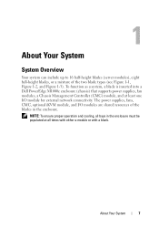
... operation and cooling, all times with either a module or with a blank. To function as a system, a blade is inserted into a Dell PowerEdge M1000e enclosure (chassis) that supports power supplies, fan modules, a Chassis Management Controller (CMC) module, and at all bays in the enclosure. About Your System 7 The power supplies, fans, CMC, optional iKVM module, and I /O module for...
... operation and cooling, all times with either a module or with a blank. To function as a system, a blade is inserted into a Dell PowerEdge M1000e enclosure (chassis) that supports power supplies, fan modules, a Chassis Management Controller (CMC) module, and at all bays in the enclosure. About Your System 7 The power supplies, fans, CMC, optional iKVM module, and I /O module for...

Dell PowerEdge M1000e Configuration Guide
Page 12
...option. Use this button to the LCD Setup Menu, Server Menu, and Enclosure Menu. LCD Setup Menu You can highlight each blade in a menu, scroll text or increase a numerical value. A dialog box displays the iDRAC IP address of the blade and any errors present. 12 About Your System Use the up screen for... and right arrows Up arrow or down arrow keys to navigate through the options in a menu and to navigate through the options in the enclosure using this condition is indicated by an amber rectangle. • To select a blade, highlight it and press the center button. An active...
...option. Use this button to the LCD Setup Menu, Server Menu, and Enclosure Menu. LCD Setup Menu You can highlight each blade in a menu, scroll text or increase a numerical value. A dialog box displays the iDRAC IP address of the blade and any errors present. 12 About Your System Use the up screen for... and right arrows Up arrow or down arrow keys to navigate through the options in a menu and to navigate through the options in the enclosure using this condition is indicated by an amber rectangle. • To select a blade, highlight it and press the center button. An active...
Dell PowerEdge M1000e Configuration Guide
Page 13
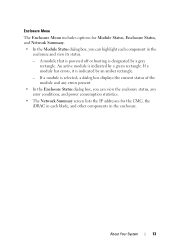
... a module has errors, it is indicated by an amber rectangle. - About Your System 13 Enclosure Menu The Enclosure Menu includes options for the CMC, the iDRAC in each component in the enclosure. A module that is powered off or booting is selected, a dialog box displays the current ... IP addresses for Module Status, Enclosure Status, and Network Summary. • In the Module Status dialog box, you can view the enclosure status, any errors present. • In the Enclosure Status dialog box, you can highlight each blade, and other components in the enclosure and view its status. - ...
... a module has errors, it is indicated by an amber rectangle. - About Your System 13 Enclosure Menu The Enclosure Menu includes options for the CMC, the iDRAC in each component in the enclosure. A module that is powered off or booting is selected, a dialog box displays the current ... IP addresses for Module Status, Enclosure Status, and Network Summary. • In the Module Status dialog box, you can view the enclosure status, any errors present. • In the Enclosure Status dialog box, you can highlight each blade, and other components in the enclosure and view its status. - ...
Dell PowerEdge M1000e Configuration Guide
Page 25
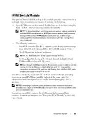
...sees the same video and be accessed from 640 x 480 at 60 Hz up to access the CMC using the blade's iDRAC interface (access is only used for tiering with Dell and Avocent analog KVM and KVM over IP switches with Analog Rack Interface (ARI) ports, and does not support... mouse. NOTE: By default (enabled), a console session to a given blade is not an Ethernet network interface port. NOTE: Connecting a keyboard, video, and mouse to the enclosure front panel disables video output to disable the sharing of the enclosure, providing front or rear panel KVM functionality, but not at 75 Hz...
...sees the same video and be accessed from 640 x 480 at 60 Hz up to access the CMC using the blade's iDRAC interface (access is only used for tiering with Dell and Avocent analog KVM and KVM over IP switches with Analog Rack Interface (ARI) ports, and does not support... mouse. NOTE: By default (enabled), a console session to a given blade is not an Ethernet network interface port. NOTE: Connecting a keyboard, video, and mouse to the enclosure front panel disables video output to disable the sharing of the enclosure, providing front or rear panel KVM functionality, but not at 75 Hz...
Dell PowerEdge M1000e Configuration Guide
Page 27
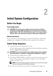
...modules, as the system does not operate at support.dell.com/manuals. NOTE: Connecting a keyboard, video, and mouse to the enclosure front panel disables video output to the iKVM back panel port. 4 Press the power button on the blades (server modules) until you need the IP address..., subnet mask, and gateway to configure the CMC and other modules in a rack. See Figure 1-4. Initial System Configuration 27 2 Initial System Configuration Before You Begin Power Requirements CAUTION: The enclosure power supplies must be...
...modules, as the system does not operate at support.dell.com/manuals. NOTE: Connecting a keyboard, video, and mouse to the enclosure front panel disables video output to the iKVM back panel port. 4 Press the power button on the blades (server modules) until you need the IP address..., subnet mask, and gateway to configure the CMC and other modules in a rack. See Figure 1-4. Initial System Configuration 27 2 Initial System Configuration Before You Begin Power Requirements CAUTION: The enclosure power supplies must be...

Dell PowerEdge M1000e Configuration Guide
Page 28
... the LCD Configuration Wizard" on page 30. 6 Configure the IO modules to quickly configure the CMC and iDRAC management interfaces and manage the enclosure remotely. 5 Configure the CMC network settings. You can power on page 47. 7 Once the Ethernet and Fibre Channel switches are configured,...CMC network settings. 28 Initial System Configuration Configuring the CMC Network Settings Using the LCD Configuration Wizard When you first start up your server blades. See "Configuring the I/O Modules" on your system, the screen on the LCD module directs you can change this address to a ...
... the LCD Configuration Wizard" on page 30. 6 Configure the IO modules to quickly configure the CMC and iDRAC management interfaces and manage the enclosure remotely. 5 Configure the CMC network settings. You can power on page 47. 7 Once the Ethernet and Fibre Channel switches are configured,...CMC network settings. 28 Initial System Configuration Configuring the CMC Network Settings Using the LCD Configuration Wizard When you first start up your server blades. See "Configuring the I/O Modules" on your system, the screen on the LCD module directs you can change this address to a ...
Dell PowerEdge M1000e Configuration Guide
Page 29
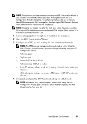
NOTE: The option to configure the enclosure using the LCD Configuration Wizard. Blade number 17 is set a static IP address for DHCP mode. Static IP address, subnet mask, and gateway values (if static mode was selected) 4 If required, ... a Management Station and CLI" on page 33. NOTE: The CMC external management network mode is a direct local connection to change the setting using the 17th Blade feature on the embedded iKVM module. To use the RACADM CLI or the webbased GUI to the CMC. 1 Choose a language from the options presented in...
NOTE: The option to configure the enclosure using the LCD Configuration Wizard. Blade number 17 is set a static IP address for DHCP mode. Static IP address, subnet mask, and gateway values (if static mode was selected) 4 If required, ... a Management Station and CLI" on page 33. NOTE: The CMC external management network mode is a direct local connection to change the setting using the 17th Blade feature on the embedded iKVM module. To use the RACADM CLI or the webbased GUI to the CMC. 1 Choose a language from the options presented in...
Dell PowerEdge M1000e Configuration Guide
Page 41
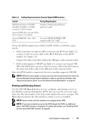
...this cable to the ARI port on the external switch. • If the switch requires a USB SIP (see the list of blades. NOTE: Server names and slot numbers are assigned by slot. Initial System Configuration 41 Cabling Requirements for External Digital KVM Switches Switch Tiering ...42. See Figure 1-16. NOTE: When the local system is connected, the server modules appear in the M1000e enclosure through the iKVM. NOTE: If you must also resynchronize the server list from a Dell 2161DS, 180AS, or 2160AS console switch: • If the switch does not require a SIP to connect...
...this cable to the ARI port on the external switch. • If the switch requires a USB SIP (see the list of blades. NOTE: Server names and slot numbers are assigned by slot. Initial System Configuration 41 Cabling Requirements for External Digital KVM Switches Switch Tiering ...42. See Figure 1-16. NOTE: When the local system is connected, the server modules appear in the M1000e enclosure through the iKVM. NOTE: If you must also resynchronize the server list from a Dell 2161DS, 180AS, or 2160AS console switch: • If the switch does not require a SIP to connect...
Dell PowerEdge M1000e Configuration Guide
Page 48
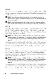
... Gb Ethernet, DDR/QDR Infiniband, and 4 Gbps or 8 Gbps Fibre Channel modules. To communicate with an I /O module in the Fabric B slots, a blade must have a matching mezzanine card installed in a Fabric C mezzanine card location. To communicate with an I /O module in the Fabric C slots...NOTE: Fabric A supports KR (10 Gbps standard) if the midplane version in each blade dictate Fabric A as indicated by the color-coded label on page 49. Modules designed for Fabric B or Fabric C cannot be installed in the enclosure is 1.1 or later. NOTE: Fabric B supports up to 16 Gbps Fibre Channel...
... Gb Ethernet, DDR/QDR Infiniband, and 4 Gbps or 8 Gbps Fibre Channel modules. To communicate with an I /O module in the Fabric B slots, a blade must have a matching mezzanine card installed in a Fabric C mezzanine card location. To communicate with an I /O module in the Fabric C slots...NOTE: Fabric A supports KR (10 Gbps standard) if the midplane version in each blade dictate Fabric A as indicated by the color-coded label on page 49. Modules designed for Fabric B or Fabric C cannot be installed in the enclosure is 1.1 or later. NOTE: Fabric B supports up to 16 Gbps Fibre Channel...

Dell PowerEdge M1000e Configuration Guide
Page 53
...-tab. If your network uses static IP addressing, enter an IP address, subnet mask and gateway. 5 When you have been configured and connected, the enclosure's blades can support: • A 10 Gb Ethernet module with four optical SFP+ connectors • A 10 Gb Ethernet module with three copper CX4 uplinks &#...Enabled if your network. - The expansion slot on the front panel can be installed in Fabric A, B, or C. 3 Select the Setup tab. Dell PowerConnect-KR 8024-k Switch The PowerConnect M8024-k switch provides 16 internal 10 GbE ports, four external 10 GbE SFP+ ports, and one 10 GbE ...
...-tab. If your network uses static IP addressing, enter an IP address, subnet mask and gateway. 5 When you have been configured and connected, the enclosure's blades can support: • A 10 Gb Ethernet module with four optical SFP+ connectors • A 10 Gb Ethernet module with three copper CX4 uplinks &#...Enabled if your network. - The expansion slot on the front panel can be installed in Fabric A, B, or C. 3 Select the Setup tab. Dell PowerConnect-KR 8024-k Switch The PowerConnect M8024-k switch provides 16 internal 10 GbE ports, four external 10 GbE SFP+ ports, and one 10 GbE ...
Dell PowerEdge M1000e Configuration Guide
Page 55
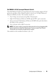
...Ethernet (DCB/FCoE) ports that link to travel over 10 Gbps Enhanced Ethernet (DCB) networks. This module can be installed in the enclosure. • One serial port with this module. Configuring the I/O Modules 55 NOTE: This switch module includes Short Wave Small Form Factor... Pluggable (SFP) optical transceivers in the Fibre Channel ports. Dell M8428-k 10 Gb Converged Network Switch The Dell M8428-k 10 Gb Converged Network switch module supports FCoE protocols and allows Fibre Channel traffic to the blades in Fabric A, B, or C. To ensure proper Fibre Channel functionality...
...Ethernet (DCB/FCoE) ports that link to travel over 10 Gbps Enhanced Ethernet (DCB) networks. This module can be installed in the enclosure. • One serial port with this module. Configuring the I/O Modules 55 NOTE: This switch module includes Short Wave Small Form Factor... Pluggable (SFP) optical transceivers in the Fibre Channel ports. Dell M8428-k 10 Gb Converged Network Switch The Dell M8428-k 10 Gb Converged Network switch module supports FCoE protocols and allows Fibre Channel traffic to the blades in Fabric A, B, or C. To ensure proper Fibre Channel functionality...
Dell PowerEdge M1000e Configuration Guide
Page 57
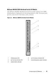
Mellanox M2401G DDR Infiniband Switch I/O Module The Mellanox M2401G Infiniband switch I /O Modules 57 Mellanox M2401G Infiniband Switch Module 1 2 3 4 5 1 Infiniband ports (8) 3 port activity indicators (8) 5 module status indicator 2 port link status indicators (8) 4 module diagnostic power indicator Configuring the I /O module includes 24 4x DDR Infiniband ports. Figure 3-6. Eight ports are external uplink ports, while 16 internal ports provide connectivity to the blades in the enclosure.
Mellanox M2401G DDR Infiniband Switch I/O Module The Mellanox M2401G Infiniband switch I /O Modules 57 Mellanox M2401G Infiniband Switch Module 1 2 3 4 5 1 Infiniband ports (8) 3 port activity indicators (8) 5 module status indicator 2 port link status indicators (8) 4 module diagnostic power indicator Configuring the I /O module includes 24 4x DDR Infiniband ports. Figure 3-6. Eight ports are external uplink ports, while 16 internal ports provide connectivity to the blades in the enclosure.

Technical Guide
Page 46
This technology works with any M-Series blade enclosure to lock the World Wide Name (WWN) of the Fibre Channel controller and Media Access Control (MAC) of the Ethernet and iSCSI controller into a blade slot, instead of all MAC/WWNs in the chassis by slot and be assured... these will never change • Efficiently integrate into existing management and network infrastructure PowerEdge M1000e Technical Guide 45 This capability allows quick, painless connection and reduces downtime. Dell's patent-pending...
This technology works with any M-Series blade enclosure to lock the World Wide Name (WWN) of the Fibre Channel controller and Media Access Control (MAC) of the Ethernet and iSCSI controller into a blade slot, instead of all MAC/WWNs in the chassis by slot and be assured... these will never change • Efficiently integrate into existing management and network infrastructure PowerEdge M1000e Technical Guide 45 This capability allows quick, painless connection and reduces downtime. Dell's patent-pending...

Technical Guide
Page 68
Connection to vKVM and vMedia is possible to connect the following Dell\Avocent KVMIP switches to the iKVM card in the M1000e blade enclosure using a CAT5 cable. • Dell: o 2161DS-2 o 4161DS o 2321DS o 180AS o 2160AS • Avocent: o All DSR xx20, xx30, xx35 models o All Mergepoint Unity models For ...USB Flash Drive, USB ISO image and USB Floppy over an IP interface. Dell emulation of the Dell PowerEdge Modular Systems Hardware Owner's Manual, in the CMC User Guide, and at dell.avocent.com. PowerEdge M1000e Technical Guide 67 More information on the iKVM can be found in the iKVM...
Connection to vKVM and vMedia is possible to connect the following Dell\Avocent KVMIP switches to the iKVM card in the M1000e blade enclosure using a CAT5 cable. • Dell: o 2161DS-2 o 4161DS o 2321DS o 180AS o 2160AS • Avocent: o All DSR xx20, xx30, xx35 models o All Mergepoint Unity models For ...USB Flash Drive, USB ISO image and USB Floppy over an IP interface. Dell emulation of the Dell PowerEdge Modular Systems Hardware Owner's Manual, in the CMC User Guide, and at dell.avocent.com. PowerEdge M1000e Technical Guide 67 More information on the iKVM can be found in the iKVM...

