Hardware Owners Manual
Page 4
... Event 46 SEL Generator ID 46 Sensor Data Record 47 Other Information You May Need 52 C6220 Fresh Air Support 52 C6220 II System Configuration Limitations by Intel Xeon Processor 57 E5-2600 v2 product family 57 C6220 II Fresh Air Support 59 Micro SD Card and SD Card Socket Location 64 2 Using the System...
... Event 46 SEL Generator ID 46 Sensor Data Record 47 Other Information You May Need 52 C6220 Fresh Air Support 52 C6220 II System Configuration Limitations by Intel Xeon Processor 57 E5-2600 v2 product family 57 C6220 II Fresh Air Support 59 Micro SD Card and SD Card Socket Location 64 2 Using the System...
Hardware Owners Manual
Page 11
... Troubleshooting a Hard Drive 300 Troubleshooting a Storage Controller 301 Troubleshooting Expansion Cards 302 Troubleshooting Processors 303 IRQ Assignment Conflicts 304 5 Jumpers and Connectors 305 C6220 II System Board Connectors 305 C6220 System Board Connectors 306 Backplane Connectors 308 3.5" Hard-Drive Direct Backplane 308 2.5" Hard-Drive Direct Backplane 310 2.5" Hard-Drive Expander Backplane 312 Middle...
... Troubleshooting a Hard Drive 300 Troubleshooting a Storage Controller 301 Troubleshooting Expansion Cards 302 Troubleshooting Processors 303 IRQ Assignment Conflicts 304 5 Jumpers and Connectors 305 C6220 II System Board Connectors 305 C6220 System Board Connectors 306 Backplane Connectors 308 3.5" Hard-Drive Direct Backplane 308 2.5" Hard-Drive Direct Backplane 310 2.5" Hard-Drive Expander Backplane 312 Middle...
Hardware Owners Manual
Page 12
Sensor Board Connectors 319 Jumper Settings 320 System Configuration Jumper Settings on the C6220 II System Board 320 System Configuration Jumper Settings on the C6220 System Board 321 Direct Backplane Jumper Settings 322 6 Getting Help 323 Contacting Dell 323 7 Index 324 12 | Contents
Sensor Board Connectors 319 Jumper Settings 320 System Configuration Jumper Settings on the C6220 II System Board 320 System Configuration Jumper Settings on the C6220 System Board 321 Direct Backplane Jumper Settings 322 6 Getting Help 323 Contacting Dell 323 7 Index 324 12 | Contents
Hardware Owners Manual
Page 14
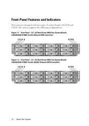
Front-Panel Features and Indicators This system is designed with two types of system boards: C6220 II and C6220. Front Panel−3.5" x12 Hard Drives With Two System Boards (C6220/C6220 II RAID Card & C6220 II Onboard SATA Controller) 14 | About Your System The system supports the following configurations: Figure 1-1. Front Panel−3.5" x12 Hard Drives With Four System Boards (C6220/C6220 II RAID Card & Onboard SATA Controller) Figure 1-2.
Front-Panel Features and Indicators This system is designed with two types of system boards: C6220 II and C6220. Front Panel−3.5" x12 Hard Drives With Two System Boards (C6220/C6220 II RAID Card & C6220 II Onboard SATA Controller) 14 | About Your System The system supports the following configurations: Figure 1-1. Front Panel−3.5" x12 Hard Drives With Four System Boards (C6220/C6220 II RAID Card & Onboard SATA Controller) Figure 1-2.
Hardware Owners Manual
Page 15
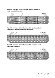
Front Panel−2.5" x24 Hard Drives With Four System Boards (C6220/C6220 II RAID Card & Onboard SATA Controller) Figure 1-5. Front Panel−2.5" x16 Hard Drives With Two System Boards (C6220/C6220 II RAID Card) About Your System | 15 Front Panel−3.5" x6 Hard Drives With Two System Board (C6220 Onboard SATA Controller) Figure 1-4. Figure 1-3.
Front Panel−2.5" x24 Hard Drives With Four System Boards (C6220/C6220 II RAID Card & Onboard SATA Controller) Figure 1-5. Front Panel−2.5" x16 Hard Drives With Two System Boards (C6220/C6220 II RAID Card) About Your System | 15 Front Panel−3.5" x6 Hard Drives With Two System Board (C6220 Onboard SATA Controller) Figure 1-4. Figure 1-3.
Hardware Owners Manual
Page 16
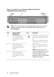
... to display an image, depending on the amount of the 2.5-inch hard drive expander configuration support, see the HDD Zoning configuration tool at dell.com/support. The power-on the direction details of DIMM installed in the system. 16 | About Your System Front Panel−2.5" x12... Hard Drives With two System Board (C6220/C6220 II Onboard SATA Controller) NOTE: For more information on indicator turns to system state indicator/ green when the system power is power button for...
... to display an image, depending on the amount of the 2.5-inch hard drive expander configuration support, see the HDD Zoning configuration tool at dell.com/support. The power-on the direction details of DIMM installed in the system. 16 | About Your System Front Panel−2.5" x12... Hard Drives With two System Board (C6220/C6220 II Onboard SATA Controller) NOTE: For more information on indicator turns to system state indicator/ green when the system power is power button for...
Hardware Owners Manual
Page 33
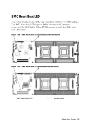
The BMC heart beat LED is connected, the LED lights. When the system AC power is green. When BMC firmware is ready, the BMC heart beat LED blinks. BMC Heart Beat LED on the C6220 System Board 1 BMC heart beat LED 2 system board About Your System | 33 BMC Heart Beat LED on the System Board C6220 II Figure 1-27. Figure 1-26. BMC Heart Beat LED The system board provides BMC heart beat LED (LED17) for BMC debugs.
The BMC heart beat LED is connected, the LED lights. When the system AC power is green. When BMC firmware is ready, the BMC heart beat LED blinks. BMC Heart Beat LED on the C6220 System Board 1 BMC heart beat LED 2 system board About Your System | 33 BMC Heart Beat LED on the System Board C6220 II Figure 1-27. Figure 1-26. BMC Heart Beat LED The system board provides BMC heart beat LED (LED17) for BMC debugs.
Hardware Owners Manual
Page 57
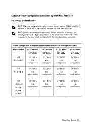
... NOTE: The full configuration includes two processors, sixteen DIMMs, one PCI-E card for 1U node/two PCI-E cards for 2U node, and one mezzanine card. C6220 II System Configuration Limitations by Intel Xeon Processor E5-2600 v2 product family Processor Bin 1U (1-4 Node) 3.5" HDDs 2U (1-2 Node) 3.5" HDDs 1U (1-4 Node) 2.5" HDDs 2U (1-2 Node...
... NOTE: The full configuration includes two processors, sixteen DIMMs, one PCI-E card for 1U node/two PCI-E cards for 2U node, and one mezzanine card. C6220 II System Configuration Limitations by Intel Xeon Processor E5-2600 v2 product family Processor Bin 1U (1-4 Node) 3.5" HDDs 2U (1-2 Node) 3.5" HDDs 1U (1-4 Node) 2.5" HDDs 2U (1-2 Node...
Hardware Owners Manual
Page 59
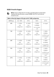
..., w/o mezzanine card 8* HDDs 16 DIMMs w/o mezzanine or PCI-E card 4* HDDs 8 DIMMs w/o PCI-E card, w/o mezzanine card 4* HDDs 8 DIMMs w/o PCI-E card, w/o mezzanine card About Your System | 59 C6220 II Fresh Air Support NOTE: The full configuration for 1U node is equiped with one mezzanine card.
..., w/o mezzanine card 8* HDDs 16 DIMMs w/o mezzanine or PCI-E card 4* HDDs 8 DIMMs w/o PCI-E card, w/o mezzanine card 4* HDDs 8 DIMMs w/o PCI-E card, w/o mezzanine card About Your System | 59 C6220 II Fresh Air Support NOTE: The full configuration for 1U node is equiped with one mezzanine card.
Hardware Owners Manual
Page 157
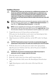
... the release lever on the processor socket in the processor 0 (for the socket location, see "C6220 II System Board Connectors" on page 305 and "C6220 System Board Connectors" on your product documentation, or as directed by Dell is positioned correctly, it engages easily into the socket. 4 Close the processor shield. 5 Rotate the...in your system. 1 Unpack the processor if it snaps into place. 6 Using a clean lint-free cloth, remove the thermal grease from support.dell.com. When the processor is not covered by a certified service technician. Installing System Components | 157
... the release lever on the processor socket in the processor 0 (for the socket location, see "C6220 II System Board Connectors" on page 305 and "C6220 System Board Connectors" on your product documentation, or as directed by Dell is positioned correctly, it engages easily into the socket. 4 Close the processor shield. 5 Rotate the...in your system. 1 Unpack the processor if it snaps into place. 6 Using a clean lint-free cloth, remove the thermal grease from support.dell.com. When the processor is not covered by a certified service technician. Installing System Components | 157
Hardware Owners Manual
Page 198
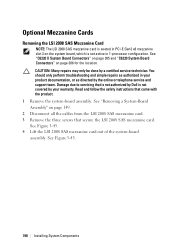
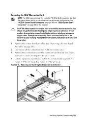
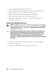
See "Removing a System-Board Assembly" on page 306 for the location. See Figure 3-43. 198 | Installing System Components See "C6220 II System Board Connectors" on page 305 and "C6220 System Board Connectors" on page 149. 2 Disconnect all the cables from the LSI 2008 SAS mezzanine card. 3 Remove the three screws ...that secure the LSI 2008 SAS mezzanine card. CAUTION: Many repairs may only be done by Dell is not active in your ...
See "Removing a System-Board Assembly" on page 306 for the location. See Figure 3-43. 198 | Installing System Components See "C6220 II System Board Connectors" on page 305 and "C6220 System Board Connectors" on page 149. 2 Disconnect all the cables from the LSI 2008 SAS mezzanine card. 3 Remove the three screws ...that secure the LSI 2008 SAS mezzanine card. CAUTION: Many repairs may only be done by Dell is not active in your ...
Hardware Owners Manual
Page 205
...3-19 for the location. Figure 3-49. Removing and Installing the Expansion-Card Bracket Installing System Components | 205 See "C6220 II System Board Connectors" on page 305 and "C6220 System Board Connectors" on page 306 for 2U node. Read and follow the safety instructions that secure the expansion-card ...for 2U node. 4 Lift the expansion-card bracket out of the system-board assembly. Damage due to servicing that is not authorized by Dell is not active in a one-processor configuration. See Figure 3-49 for 1U node. Removing the 1GbE Mezzanine Card NOTE: The 1GbE mezzanine...
...3-19 for the location. Figure 3-49. Removing and Installing the Expansion-Card Bracket Installing System Components | 205 See "C6220 II System Board Connectors" on page 305 and "C6220 System Board Connectors" on page 306 for 2U node. Read and follow the safety instructions that secure the expansion-card ...for 2U node. 4 Lift the expansion-card bracket out of the system-board assembly. Damage due to servicing that is not authorized by Dell is not active in a one-processor configuration. See Figure 3-49 for 1U node. Removing the 1GbE Mezzanine Card NOTE: The 1GbE mezzanine...
Hardware Owners Manual
Page 208
... Components See "Installing a System-Board Assembly" on the system board, which is not active in 1-processor configuration. See "C6220 II System Board Connectors" on page 305 and "C6220 System Board Connectors" on page 149. 2 Disconnect all the cables to servicing that came with the product. 1 Remove the...due to the 1GbE mezzanine card. 8 Replace the system-board assembly. Read and follow the safety instructions that is not authorized by Dell is seated in your warranty. You should only perform troubleshooting and simple repairs as authorized in PCI-E Gen3 x8 mezzanine slot 3 ...
... Components See "Installing a System-Board Assembly" on the system board, which is not active in 1-processor configuration. See "C6220 II System Board Connectors" on page 305 and "C6220 System Board Connectors" on page 149. 2 Disconnect all the cables to servicing that came with the product. 1 Remove the...due to the 1GbE mezzanine card. 8 Replace the system-board assembly. Read and follow the safety instructions that is not authorized by Dell is seated in your warranty. You should only perform troubleshooting and simple repairs as authorized in PCI-E Gen3 x8 mezzanine slot 3 ...
Hardware Owners Manual
Page 214
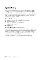
... up . The optimized memory module installation sequence is 1/2/3/4/5/6/7/8. See Table 3-2 and Table 3-3 for possible memory configurations. 214 | Installing System Components See "C6220 II System Board Connectors" on page 305 and "C6220 System Board Connectors" on processor 1's DIMM slot 1 in order to be booted up to sixteen unbuffered or registered DDR3-1333MHz (1600MHz @2 memory...
... up . The optimized memory module installation sequence is 1/2/3/4/5/6/7/8. See Table 3-2 and Table 3-3 for possible memory configurations. 214 | Installing System Components See "C6220 II System Board Connectors" on page 305 and "C6220 System Board Connectors" on processor 1's DIMM slot 1 in order to be booted up to sixteen unbuffered or registered DDR3-1333MHz (1600MHz @2 memory...
Hardware Owners Manual
Page 305
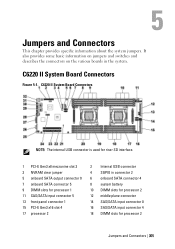
C6220 II System Board Connectors NOTE: The internal USB connector is used for riser SD interface. 1 PCI-E Gen3 x8 mezzanine slot 3 3 NVRAM clear jumper 5 onboard SATA output ... PCI-E Gen3 x16 slot 4 17 processor 2 2 Internal USB connector 4 SGPIO in the system. 5 Jumpers and Connectors This chapter provides specific information about the system jumpers. C6220 II System Board Connectors Figure 5-1.
C6220 II System Board Connectors NOTE: The internal USB connector is used for riser SD interface. 1 PCI-E Gen3 x8 mezzanine slot 3 3 NVRAM clear jumper 5 onboard SATA output ... PCI-E Gen3 x16 slot 4 17 processor 2 2 Internal USB connector 4 SGPIO in the system. 5 Jumpers and Connectors This chapter provides specific information about the system jumpers. C6220 II System Board Connectors Figure 5-1.
Hardware Owners Manual
Page 320
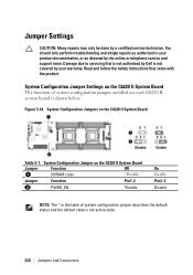
... not authorized by Dell is not covered by your product documentation, or as directed by a certified service technician. You should only perform troubleshooting and simple repairs as authorized in the table of system configuration jumper installed on the C6220 II System Board The... state is shown below: Figure 5-18. System Configuration Jumper Settings on each C6220 II system board is not active state. 320 | Jumpers and Connectors System Configuration Jumpers on the C6220 II System Board Jumper Function Off NVRAM clear *Disable Jumper Function Pin1-2 PWRD_EN *Enable...
... not authorized by Dell is not covered by your product documentation, or as directed by a certified service technician. You should only perform troubleshooting and simple repairs as authorized in the table of system configuration jumper installed on the C6220 II System Board The... state is shown below: Figure 5-18. System Configuration Jumper Settings on each C6220 II system board is not active state. 320 | Jumpers and Connectors System Configuration Jumpers on the C6220 II System Board Jumper Function Off NVRAM clear *Disable Jumper Function Pin1-2 PWRD_EN *Enable...
Hardware Owners Manual
Page 324
... drive backplane for expander configuration, 275 backplane jumper settings, 322 batteries troubleshooting, 295 battery (system) replacing, 220 blank hard drive, 140, 141 C C6220 II system board connectors, 305 C6220 system board connectors, 306 324 | Index 7 cable routing LSI 9265-8i card (1U node), 176 LSI 9265-8i card (2U node), 184 onboard..., 282, 287 Riser card, 197 SAS mezzanine card (1U node), 200 SAS mezzanine card (2U node), 201 collecting system event log, 34, 46 contacting dell, 323 cooling fans installing, 234 removing, 232 troubleshooting, 297 D damaged systems troubleshooting, 294...
... drive backplane for expander configuration, 275 backplane jumper settings, 322 batteries troubleshooting, 295 battery (system) replacing, 220 blank hard drive, 140, 141 C C6220 II system board connectors, 305 C6220 system board connectors, 306 324 | Index 7 cable routing LSI 9265-8i card (1U node), 176 LSI 9265-8i card (2U node), 184 onboard..., 282, 287 Riser card, 197 SAS mezzanine card (1U node), 200 SAS mezzanine card (2U node), 201 collecting system event log, 34, 46 contacting dell, 323 cooling fans installing, 234 removing, 232 troubleshooting, 297 D damaged systems troubleshooting, 294...
Hardware Owners Manual
Page 328
... troubleshooting, 301 SAS Mezzanine card installing, 199 removing, 198 SAS RAID controller daughter card troubleshooting, 301 startup accessing system features, 13 support C6220 fresh air, 52 C6220 II fresh air f, 59 contacting Dell, 323 system closing, 231 opening, 230 system board installing, 224 jumper settings, 320, 321 removing, 222 system board assembly installing, 150...
... troubleshooting, 301 SAS Mezzanine card installing, 199 removing, 198 SAS RAID controller daughter card troubleshooting, 301 startup accessing system features, 13 support C6220 fresh air, 52 C6220 II fresh air f, 59 contacting Dell, 323 system closing, 231 opening, 230 system board installing, 224 jumper settings, 320, 321 removing, 222 system board assembly installing, 150...
Using the Baseboard Management Controller
Page 1
Dell PowerEdge C6220 II Using the Baseboard Management Controller FILE LOCATION: D:\Projects\User Guide\Server\Dell\C6220II\BMC\C6220II_BMC_HOM_tp.fm Template Last Updated -03/06/2010
Dell PowerEdge C6220 II Using the Baseboard Management Controller FILE LOCATION: D:\Projects\User Guide\Server\Dell\C6220II\BMC\C6220II_BMC_HOM_tp.fm Template Last Updated -03/06/2010
Using the Baseboard Management Controller
Page 5
... Controller The key component in a system event log (SEL) for later examination. System software communicates with BMC using a keyboard controller style (KCS) interface. Supported Platform PowerEdge C6220 II BMC Key Features and Functions The features supported by lighting chassis LED indicator and Platform Event Trap (PET) Template Last Updated - 2/7/2007 5 BMC is the...
... Controller The key component in a system event log (SEL) for later examination. System software communicates with BMC using a keyboard controller style (KCS) interface. Supported Platform PowerEdge C6220 II BMC Key Features and Functions The features supported by lighting chassis LED indicator and Platform Event Trap (PET) Template Last Updated - 2/7/2007 5 BMC is the...


