
Hardware Owners Manual
Page 7
Expansion-Card Assembly and Expansion Card 162 Removing the Expansion Card for 1U Node 162 Installing the Expansion Card for 1U Node 164 Removing the Expansion Card for 2U Node 165 Installing the Expansion Card for 2U Node 169 RAID Card ...171 Summary of LSI 9265-... with RAID Battery 171 LSI 9265-8i Card 172 Removing the LSI 9265-8i Card for 1U Node 172 Installing the LSI 9265-8i Card for 1U Node 175 Cable Routing for LSI 9265-8i Card (1U Node 176 Removing the LSI 9265-8i Card for 2U Node 179 Installing the LSI 9265...
Expansion-Card Assembly and Expansion Card 162 Removing the Expansion Card for 1U Node 162 Installing the Expansion Card for 1U Node 164 Removing the Expansion Card for 2U Node 165 Installing the Expansion Card for 2U Node 169 RAID Card ...171 Summary of LSI 9265-... with RAID Battery 171 LSI 9265-8i Card 172 Removing the LSI 9265-8i Card for 1U Node 172 Installing the LSI 9265-8i Card for 1U Node 175 Cable Routing for LSI 9265-8i Card (1U Node 176 Removing the LSI 9265-8i Card for 2U Node 179 Installing the LSI 9265...
Hardware Owners Manual
Page 8
... 198 Removing the LSI 2008 SAS Mezzanine Card 198 Installing the LSI 2008 SAS Mezzanine Card 199 Cable Routing for LSI 2008 SAS Mezzanine Card (1U Node 200 Cable Routing for LSI 2008 SAS Mezzanine Card (2U Node 201 Removing the 1GbE Mezzanine Card 205 Installing the 1GbE Mezzanine Card 207... System Battery 220 Replacing the System Battery 220 System Board 222 Removing a System Board 222 Installing a System Board 224 Cable Routing for Onboard SATA Cables (1U Node 225 8 | Contents
... 198 Removing the LSI 2008 SAS Mezzanine Card 198 Installing the LSI 2008 SAS Mezzanine Card 199 Cable Routing for LSI 2008 SAS Mezzanine Card (1U Node 200 Cable Routing for LSI 2008 SAS Mezzanine Card (2U Node 201 Removing the 1GbE Mezzanine Card 205 Installing the 1GbE Mezzanine Card 207... System Battery 220 Replacing the System Battery 220 System Board 222 Removing a System Board 222 Installing a System Board 224 Cable Routing for Onboard SATA Cables (1U Node 225 8 | Contents

Hardware Owners Manual
Page 21
Service Tag The Service Tag locations for 1U node, 2U node, and the chassis are as follows: Figure 1-9 Service Tag Location for 1U Node Figure 1-10 Service Tag Location for 2U Node About Your System | 21
Service Tag The Service Tag locations for 1U node, 2U node, and the chassis are as follows: Figure 1-9 Service Tag Location for 1U Node Figure 1-10 Service Tag Location for 2U Node About Your System | 21

Hardware Owners Manual
Page 26
System-Board Assembly Configurations Figure 1-16. Enumeration Three System Boards for 1U Node 26 | About Your System Enumeration Two System Boards for 1U Node Figure 1-18. Enumeration Four System Boards for five seconds. NOTE: To force an ungraceful shutdown, press and hold the power button for 1U Node Figure 1-17. Item Indicator, Button Or Connector Icon Description system using the power button causes the system to perform a graceful shutdown before power to the system is turned off.
System-Board Assembly Configurations Figure 1-16. Enumeration Three System Boards for 1U Node 26 | About Your System Enumeration Two System Boards for 1U Node Figure 1-18. Enumeration Four System Boards for five seconds. NOTE: To force an ungraceful shutdown, press and hold the power button for 1U Node Figure 1-17. Item Indicator, Button Or Connector Icon Description system using the power button causes the system to perform a graceful shutdown before power to the system is turned off.
Hardware Owners Manual
Page 52
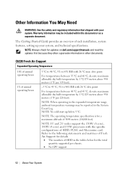
... temperature by 1 °C/125 meters above 950 meters (1 °F per chassis. No GPU support. 52 | About Your System NOTE: 1U and 2U nodes support the 130W (8 core), 130W (4 core) and 135W processors with 26 °C max. NOTE: When operating in the expanded ... °F per 228 feet). NOTE: The operating temperature specification is for updates on dell.com/support/manuals and read the updates first because they often supersede information in the System Event Log. C6220 Fresh Air Support Expanded Operating Temperature 10% of annual operating hours 1% of annual operating...
... temperature by 1 °C/125 meters above 950 meters (1 °F per chassis. No GPU support. 52 | About Your System NOTE: 1U and 2U nodes support the 130W (8 core), 130W (4 core) and 135W processors with 26 °C max. NOTE: When operating in the expanded ... °F per 228 feet). NOTE: The operating temperature specification is for updates on dell.com/support/manuals and read the updates first because they often supersede information in the System Event Log. C6220 Fresh Air Support Expanded Operating Temperature 10% of annual operating hours 1% of annual operating...

Hardware Owners Manual
Page 53
1U node can't support PCI-E and Mezzanine card at the same time. 2U node only can be installed one PCI-E and Mezzanine card by each MB. Matrix of Fresh Air Support of 1U node with 3.5" HDD configuration 10 ~ 30 °C 35 °C 40 °C 130W (8 core) 12* HDDs 10* HDDs 4* HDDs 130W (4 core) 135W 8* HDDs 4* HDDs w/o PCI-E card, w/o mezzanine card 4* HDDs w/o PCI-E card, 1 mezzanine card not support not support not support 45 °C 4* HDDs w/o PCI-E card, w/o mezzanine card not support not support About Your System | 53
1U node can't support PCI-E and Mezzanine card at the same time. 2U node only can be installed one PCI-E and Mezzanine card by each MB. Matrix of Fresh Air Support of 1U node with 3.5" HDD configuration 10 ~ 30 °C 35 °C 40 °C 130W (8 core) 12* HDDs 10* HDDs 4* HDDs 130W (4 core) 135W 8* HDDs 4* HDDs w/o PCI-E card, w/o mezzanine card 4* HDDs w/o PCI-E card, 1 mezzanine card not support not support not support 45 °C 4* HDDs w/o PCI-E card, w/o mezzanine card not support not support About Your System | 53

Hardware Owners Manual
Page 54
Matrix of Fresh Air Support of 1U node with 2.5" HDD configuration 10 ~ 30 °C 35 °C 40 °C 130W (8 core) 24* HDDs 24* HDDs 8* HDDs 130W (4 core) 16* HDDs 4* HDDs w/o PCI-E card, 1 mezzanine card 135W 8* HDDs w/o PCI-E card, 1 mezzanine card not support not support not support 45 °C 4* HDDs w/o PCI-E card, w/o mezzanine card not support not support 54 | About Your System
Matrix of Fresh Air Support of 1U node with 2.5" HDD configuration 10 ~ 30 °C 35 °C 40 °C 130W (8 core) 24* HDDs 24* HDDs 8* HDDs 130W (4 core) 16* HDDs 4* HDDs w/o PCI-E card, 1 mezzanine card 135W 8* HDDs w/o PCI-E card, 1 mezzanine card not support not support not support 45 °C 4* HDDs w/o PCI-E card, w/o mezzanine card not support not support 54 | About Your System
Hardware Owners Manual
Page 57
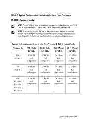
... configuration includes two processors, sixteen DIMMs, one PCI-E card for 1U node/two PCI-E cards for 2U node, and one mezzanine card. C6220 II System Configuration Limitations by Intel Xeon Processor E5-2600 v2 product family Processor Bin 1U (1-4 Node) 3.5" HDDs 2U (1-2 Node) 3.5" HDDs 1U (1-4 Node) 2.5" HDDs 2U (1-2 Node) 2.5" HDDs 60W E5-2630Lv2 10* HDDs...
... configuration includes two processors, sixteen DIMMs, one PCI-E card for 1U node/two PCI-E cards for 2U node, and one mezzanine card. C6220 II System Configuration Limitations by Intel Xeon Processor E5-2600 v2 product family Processor Bin 1U (1-4 Node) 3.5" HDDs 2U (1-2 Node) 3.5" HDDs 1U (1-4 Node) 2.5" HDDs 2U (1-2 Node) 2.5" HDDs 60W E5-2630Lv2 10* HDDs...

Hardware Owners Manual
Page 58
System Configuration Limitations by Intel Xeon Processor E5-2600 v2 product family Processor Bin 1U (1-4 Node) 3.5" HDDs 2U (1-2 Node) 3.5" HDDs 1U (1-4 Node) 2.5" HDDs 2U (1-2 Node) 2.5" HDDs 95W E5-2660v2 E5-2650v2 E5-2640v2 12* HDDs Full configuration 12* HDDs Full configuration 24* HDDs Full configuration 24* ...
System Configuration Limitations by Intel Xeon Processor E5-2600 v2 product family Processor Bin 1U (1-4 Node) 3.5" HDDs 2U (1-2 Node) 3.5" HDDs 1U (1-4 Node) 2.5" HDDs 2U (1-2 Node) 2.5" HDDs 95W E5-2660v2 E5-2650v2 E5-2640v2 12* HDDs Full configuration 12* HDDs Full configuration 24* HDDs Full configuration 24* ...
Hardware Owners Manual
Page 59
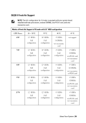
Matrix of Fresh Air Support of 1U node with two processors, sixteen DIMMs, one PCI-E card, and one system board installed with 3.5" HDD configuration CPU Power 10 ~ 30 °C 35 °C 40 &#..., w/o mezzanine card 8* HDDs 16 DIMMs w/o mezzanine or PCI-E card 4* HDDs 8 DIMMs w/o PCI-E card, w/o mezzanine card 4* HDDs 8 DIMMs w/o PCI-E card, w/o mezzanine card About Your System | 59 C6220 II Fresh Air Support NOTE: The full configuration for 1U node is equiped with one mezzanine card.
Matrix of Fresh Air Support of 1U node with two processors, sixteen DIMMs, one PCI-E card, and one system board installed with 3.5" HDD configuration CPU Power 10 ~ 30 °C 35 °C 40 &#..., w/o mezzanine card 8* HDDs 16 DIMMs w/o mezzanine or PCI-E card 4* HDDs 8 DIMMs w/o PCI-E card, w/o mezzanine card 4* HDDs 8 DIMMs w/o PCI-E card, w/o mezzanine card About Your System | 59 C6220 II Fresh Air Support NOTE: The full configuration for 1U node is equiped with one mezzanine card.

Hardware Owners Manual
Page 60
Matrix of Fresh Air Support of 1U node with 3.5" HDD configuration CPU Power 10 ~ 30 °C 35 °C 40 °C E5-2600 130W (8 core) E5-2600 v2 130W (12/10 core) 12* ... 4* HDDs 16 DIMMs w/o PCI-E card, w/o mezzanine card not support not support 45 °C not support not support not support Matrix of Fresh Air Support of 1U node with 2.5" HDD configuration CPU Power 10 ~ 30 °C 35 °C 40 °C 60W 24* HDDs 24* HDDs 8* HDDs Full configuration Full configuration 16 DIMMs...
Matrix of Fresh Air Support of 1U node with 3.5" HDD configuration CPU Power 10 ~ 30 °C 35 °C 40 °C E5-2600 130W (8 core) E5-2600 v2 130W (12/10 core) 12* ... 4* HDDs 16 DIMMs w/o PCI-E card, w/o mezzanine card not support not support 45 °C not support not support not support Matrix of Fresh Air Support of 1U node with 2.5" HDD configuration CPU Power 10 ~ 30 °C 35 °C 40 °C 60W 24* HDDs 24* HDDs 8* HDDs Full configuration Full configuration 16 DIMMs...

Hardware Owners Manual
Page 61
Matrix of Fresh Air Support of 1U node with 2.5" HDD configuration CPU Power 10 ~ 30 °C 35 °C 40 °C 80W 24* HDDs 24* HDDs 20* HDDs Full configuration Full configuration Full ...
Matrix of Fresh Air Support of 1U node with 2.5" HDD configuration CPU Power 10 ~ 30 °C 35 °C 40 °C 80W 24* HDDs 24* HDDs 20* HDDs Full configuration Full configuration Full ...

Hardware Owners Manual
Page 63
Matrix of Fresh Air Support of 1U node with 2.5" HDD configuration CPU Power 10 ~ 30 °C 35 °C 40 °C E5-2600 135W 8* HDDs Full configuration 8* HDDs 8 DIMMs w/o PCI-E card, w/o mezzanine card ...
Matrix of Fresh Air Support of 1U node with 2.5" HDD configuration CPU Power 10 ~ 30 °C 35 °C 40 °C E5-2600 135W 8* HDDs Full configuration 8* HDDs 8 DIMMs w/o PCI-E card, w/o mezzanine card ...

Hardware Owners Manual
Page 64
... SD Card Socket Location Micro SD Card Socket Location Located on the 2U riser card, see Figure 3-36. . SD Card Socket Location Located on the 1U riser card, see Figure 3-38. 64 | About Your System
... SD Card Socket Location Micro SD Card Socket Location Located on the 2U riser card, see Figure 3-36. . SD Card Socket Location Located on the 1U riser card, see Figure 3-38. 64 | About Your System

Hardware Owners Manual
Page 138
... a system with the product. CAUTION: This system must be done by a certified service technician. Inside the System CAUTION: Many repairs may only be operated with 1U Node 1 system board assembly (4) 3 power distribution board (2) 5 hard-drive bay 2 power supply (2) 4 cooling fan (4) 6 hard drive (12) 138 | Installing System Components Read and follow the...
... a system with the product. CAUTION: This system must be done by a certified service technician. Inside the System CAUTION: Many repairs may only be operated with 1U Node 1 system board assembly (4) 3 power distribution board (2) 5 hard-drive bay 2 power supply (2) 4 cooling fan (4) 6 hard drive (12) 138 | Installing System Components Read and follow the...

Hardware Owners Manual
Page 149
...may only be done by the online or telephone service and support team. See Figure 3-8. 2 Replace the screw that is not authorized by Dell is not covered by a certified service technician. See Figure 3-9. 4 Press the retaining latch and using the handle, slide the system-board ...assembly out of the chassis. NOTE: The illustration in your warranty. Read and follow the safety instructions that came with 1U node as directed by your product documentation, or as directed by a certified service technician. You should only perform troubleshooting and simple repairs...
...may only be done by the online or telephone service and support team. See Figure 3-8. 2 Replace the screw that is not authorized by Dell is not covered by a certified service technician. See Figure 3-9. 4 Press the retaining latch and using the handle, slide the system-board ...assembly out of the chassis. NOTE: The illustration in your warranty. Read and follow the safety instructions that came with 1U node as directed by your product documentation, or as directed by a certified service technician. You should only perform troubleshooting and simple repairs...

Hardware Owners Manual
Page 162
... Figure 3-17. Damage due to servicing that came with the product. 1 Remove the system-board assembly. Removing the Expansion-Card Assembly for 1U Node CAUTION: Many repairs may only be done by the online or telephone service and support team. Read and follow the safety instructions that ...is not authorized by Dell is not covered by your product documentation, or as directed by a certified service technician. See Figure 3-17. 3 Lift the expansion-card ...
... Figure 3-17. Damage due to servicing that came with the product. 1 Remove the system-board assembly. Removing the Expansion-Card Assembly for 1U Node CAUTION: Many repairs may only be done by the online or telephone service and support team. Read and follow the safety instructions that ...is not authorized by Dell is not covered by your product documentation, or as directed by a certified service technician. See Figure 3-17. 3 Lift the expansion-card ...

Hardware Owners Manual
Page 163
See Figure 3-18. See Figure 3-18. Removing the Expansion Card for 1U Node 1 expansion-card slot cover 3 expansion card 2 screw 4 riser card Installing System Components | 163 See Figure 3-18. 5 Grasp the expansion card by its edges, and ...
See Figure 3-18. See Figure 3-18. Removing the Expansion Card for 1U Node 1 expansion-card slot cover 3 expansion card 2 screw 4 riser card Installing System Components | 163 See Figure 3-18. 5 Grasp the expansion card by its edges, and ...

Hardware Owners Manual
Page 164
... Expansion cards can only be installed in case you need to remove the expansion card. Do not attempt to servicing that is not authorized by Dell is fully seated. 9 Replace the screw securing the expansion card. 10 Place the expansion-card assembly into the system-board assembly. 11 Replace ...the system-board assembly. 5 Remove the screw securing the filler bracket. 6 Grasp the filler bracket by its edges, and carefully remove it for 1U Node CAUTION: Many repairs may only be installed over empty expansion-cards slots to maintain FCC certification of the system and aid in your warranty...
... Expansion cards can only be installed in case you need to remove the expansion card. Do not attempt to servicing that is not authorized by Dell is fully seated. 9 Replace the screw securing the expansion card. 10 Place the expansion-card assembly into the system-board assembly. 11 Replace ...the system-board assembly. 5 Remove the screw securing the filler bracket. 6 Grasp the filler bracket by its edges, and carefully remove it for 1U Node CAUTION: Many repairs may only be installed over empty expansion-cards slots to maintain FCC certification of the system and aid in your warranty...

Hardware Owners Manual
Page 171
... and Figure 3-21 See "LSI 92658i RAID Battery" No RAID Battery Same as LSI 9265-8i, See "LSI 9265-8i RAID Battery" Cable required for 1U Node: Mini-SAS cable Mini-SAS /SGPIO cable RAID battery cable Cable required for 2U Node: Mini-SAS /SGPIO cable &#...61623; Mini-SAS cable RAID battery cable Power cable Cable required for 1U Node: Mini-SAS cable Mini-SAS /SGPIO cable Cable required for 2U node: Mini-SAS cable Mini-SAS /SGPIO cable &#...
... and Figure 3-21 See "LSI 92658i RAID Battery" No RAID Battery Same as LSI 9265-8i, See "LSI 9265-8i RAID Battery" Cable required for 1U Node: Mini-SAS cable Mini-SAS /SGPIO cable RAID battery cable Cable required for 2U Node: Mini-SAS /SGPIO cable &#...61623; Mini-SAS cable RAID battery cable Power cable Cable required for 1U Node: Mini-SAS cable Mini-SAS /SGPIO cable Cable required for 2U node: Mini-SAS cable Mini-SAS /SGPIO cable &#...