Configuration Guide
Page 5
Contents 1 General System Configuration 5 Other Documents You May Need 6 Initial Setup 7 Configuring Drive Mirroring 9 Additional Integrated Mirroring Guidelines 10 Connecting a USB Drive, Keyboard, and Mouse to the Server Module Front Panel 10 Installing an Operating System 10 Configuring the DRAC/MC Module 11 DRAC/MC Module ...
Contents 1 General System Configuration 5 Other Documents You May Need 6 Initial Setup 7 Configuring Drive Mirroring 9 Additional Integrated Mirroring Guidelines 10 Connecting a USB Drive, Keyboard, and Mouse to the Server Module Front Panel 10 Installing an Operating System 10 Configuring the DRAC/MC Module 11 DRAC/MC Module ...
Configuration Guide
Page 7
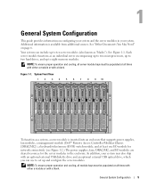
... can use to set up to eight memory modules. Figure 1-1. Additional information is inserted into an enclosure that supports power supplies, fan modules, a management module (Dell™ Remote Access Controller/Modular Chassis [DRAC/MC]), a keyboard/video/mouse (KVM) switch module, and at all times with either a module or with an optional...
... can use to set up to eight memory modules. Figure 1-1. Additional information is inserted into an enclosure that supports power supplies, fan modules, a management module (Dell™ Remote Access Controller/Modular Chassis [DRAC/MC]), a keyboard/video/mouse (KVM) switch module, and at all times with either a module or with an optional...
Configuration Guide
Page 12
...in an IM virtual disk. 7 Press and then select Save changes when the virtual disk has been fully configured. 8 Press to the powered USB hub. NOTE: The hard-drive activity indicator functions normally before and after the operating system driver initialization has occurred. 6 As disks are several ...an IM virtual disk: • All disks must be replaced and the data re-mirrored to the physical disk, maintaining data integrity. Connecting a USB Drive, Keyboard, and Mouse to the Server Module Front Panel If you must connect the monitor to operating system load, use during POST. A ...
...in an IM virtual disk. 7 Press and then select Save changes when the virtual disk has been fully configured. 8 Press to the powered USB hub. NOTE: The hard-drive activity indicator functions normally before and after the operating system driver initialization has occurred. 6 As disks are several ...an IM virtual disk: • All disks must be replaced and the data re-mirrored to the physical disk, maintaining data integrity. Connecting a USB Drive, Keyboard, and Mouse to the Server Module Front Panel If you must connect the monitor to operating system load, use during POST. A ...

Configuration Guide
Page 47
... Virtual Media dialog box allows you will behave as needed. When you have connected a device, you to connect a diskette device, a USB device, CD or DVD device to that provides optimal video quality while minimizing network traffic. You can select one CD Drive device and one... drive, or a single ISO image file on the drive. • Virtual Mass Storage Device options include a diskette drive, a USB key or other removable USB storage device, and an ISO image file on screen. Adjusting the Video Quality The Viewer Application provides video adjustments that generates excessive network...
... Virtual Media dialog box allows you will behave as needed. When you have connected a device, you to connect a diskette device, a USB device, CD or DVD device to that provides optimal video quality while minimizing network traffic. You can select one CD Drive device and one... drive, or a single ISO image file on the drive. • Virtual Mass Storage Device options include a diskette drive, a USB key or other removable USB storage device, and an ISO image file on screen. Adjusting the Video Quality The Viewer Application provides video adjustments that generates excessive network...
Getting Started Guide
Page 6
.... This video subsystem contains 16 MB of the server modules, network switch modules, power supplies, and fans. NOTE: Only Dell-supplied USB diskette drives and optical drives are supported; The systems management circuitry works in conjunction with an ATI ES1000 video controller. For...provided with this program, see "Technical Specifications." Maximum resolution is included with Service Pack 1 or later 4 Getting Started With Your System Dell recommends that monitors operation of the system fans as well as a whole, including all of SDRAM video memory (nonupgradable). • ...
.... This video subsystem contains 16 MB of the server modules, network switch modules, power supplies, and fans. NOTE: Only Dell-supplied USB diskette drives and optical drives are supported; The systems management circuitry works in conjunction with an ATI ES1000 video controller. For...provided with this program, see "Technical Specifications." Maximum resolution is included with Service Pack 1 or later 4 Getting Started With Your System Dell recommends that monitors operation of the system fans as well as a whole, including all of SDRAM video memory (nonupgradable). • ...
Getting Started Guide
Page 14
... Video type Video memory Up to two Intel Xeon Processor 5000 Sequence FBD DDR II DIMMs, with two-way interleaving, rated for 533- Supports two USB devices and video via custom cable ATI ES1000 video controller 16 MB 12 Getting Started With Your System
... Video type Video memory Up to two Intel Xeon Processor 5000 Sequence FBD DDR II DIMMs, with two-way interleaving, rated for 533- Supports two USB devices and video via custom cable ATI ES1000 video controller 16 MB 12 Getting Started With Your System
Hardware Owner's Manual (PDF)
Page 3
Contents 1 About Your System 9 Other Information You May Need 9 System Overview 10 System Status Features 10 Server Module Features 12 Using USB Diskette or USB CD Drives 16 Hard-Drive Features 16 Back-Panel Features 18 Power Supply Indicator 19 Fan Module Indicators 21 KVM Modules 22 Avocent Analog KVM ...
Contents 1 About Your System 9 Other Information You May Need 9 System Overview 10 System Status Features 10 Server Module Features 12 Using USB Diskette or USB CD Drives 16 Hard-Drive Features 16 Back-Panel Features 18 Power Supply Indicator 19 Fan Module Indicators 21 KVM Modules 22 Avocent Analog KVM ...

Hardware Owner's Manual (PDF)
Page 6
...-Up Routine 101 Checking the Equipment 101 Troubleshooting External Connections 102 Troubleshooting the Video Subsystem 102 Troubleshooting the Keyboard 103 Troubleshooting the Mouse 104 Troubleshooting USB Devices 105 Responding to a Systems Management Alert Message 105 Troubleshooting a Wet System 106 Troubleshooting a Damaged System 107 Troubleshooting System Components 107 Troubleshooting Power Supply Modules...
...-Up Routine 101 Checking the Equipment 101 Troubleshooting External Connections 102 Troubleshooting the Video Subsystem 102 Troubleshooting the Keyboard 103 Troubleshooting the Mouse 104 Troubleshooting USB Devices 105 Responding to a Systems Management Alert Message 105 Troubleshooting a Wet System 106 Troubleshooting a Damaged System 107 Troubleshooting System Components 107 Troubleshooting Power Supply Modules...

Hardware Owner's Manual (PDF)
Page 7
... Diagnostics Features 117 When to Use the System Diagnostics 118 Running the System Diagnostics 118 From the Utility Partition 118 From a USB Flash Drive 118 System Diagnostics Testing Options 119 Using the Advanced Testing Options 119 Error Messages 120 6 DIP Switch Settings and ...Help 127 Technical Assistance 127 Online Services 127 AutoTech Service 128 Automated Order-Status Service 128 Technical Support Service 128 Dell Enterprise Training and Certification 129 Problems With Your Order 129 Product Information 129 Returning Items for Warranty Repair or Credit 129 Contents ...
... Diagnostics Features 117 When to Use the System Diagnostics 118 Running the System Diagnostics 118 From the Utility Partition 118 From a USB Flash Drive 118 System Diagnostics Testing Options 119 Using the Advanced Testing Options 119 Error Messages 120 6 DIP Switch Settings and ...Help 127 Technical Assistance 127 Online Services 127 AutoTech Service 128 Automated Order-Status Service 128 Technical Support Service 128 Dell Enterprise Training and Certification 129 Problems With Your Order 129 Product Information 129 Returning Items for Warranty Repair or Credit 129 Contents ...
Hardware Owner's Manual (PDF)
Page 10
... panels. NOTE: To ensure proper operation and cooling, all times with either a server module or with an optional external USB diskette drive and an optional external USB CD drive, which you may also ship with a blank. Each server module functions as a system, a server module is... inserted into a chassis that supports power supplies, fan modules, a management module (Dell™ Remote Access Controller/Modular Chassis [DRAC/MC]), a ...
... panels. NOTE: To ensure proper operation and cooling, all times with either a server module or with an optional external USB diskette drive and an optional external USB CD drive, which you may also ship with a blank. Each server module functions as a system, a server module is... inserted into a chassis that supports power supplies, fan modules, a management module (Dell™ Remote Access Controller/Modular Chassis [DRAC/MC]), a ...

Hardware Owner's Manual (PDF)
Page 12
...indicator can only be turned off by using the custom cable supplied with your system to connect this port to two USB devices (for example, USB diskette drive, USB CD drive, USB mouse) and to video. The indicators include a power indicator, network link indicators, and a KVM module indicator. ...identification button has been pressed. Table 1-1. The server module also has a custom port on the front (see Figure 1-3). NOTE: The USB devices can be connected by pressing the identification button. Will stop blinking when the error is the default. Use the custom cable included ...
...indicator can only be turned off by using the custom cable supplied with your system to connect this port to two USB devices (for example, USB diskette drive, USB CD drive, USB mouse) and to video. The indicators include a power indicator, network link indicators, and a KVM module indicator. ...identification button has been pressed. Table 1-1. The server module also has a custom port on the front (see Figure 1-3). NOTE: The USB devices can be connected by pressing the identification button. Will stop blinking when the error is the default. Use the custom cable included ...

Hardware Owner's Manual (PDF)
Page 13
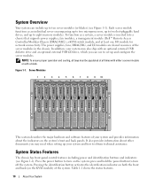
Server Module Indicators 1 2 3 4 5 6 7 1 server module power indicator 2 4 KVM selection button 5 7 custom port (with custom cable - Figure 1-3. USB [2] and video) server module power button 3 daughter card status indicator 6 KVM selection indicator Ethernet network indicator About Your System 13
Server Module Indicators 1 2 3 4 5 6 7 1 server module power indicator 2 4 KVM selection button 5 7 custom port (with custom cable - Figure 1-3. USB [2] and video) server module power button 3 daughter card status indicator 6 KVM selection indicator Ethernet network indicator About Your System 13
Hardware Owner's Manual (PDF)
Page 16
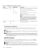
... and a SATA drive within a given server module (blade). Indicates network activity between the server module and the network switch module. The USB drives are displayed as first in the boot sequence (see "Using the System Setup Program" on Green blinking Indicates that the server module ..., you use the integrated NIC to the Ethernet switch or pass-through module. Green on page 43). NOTICE: The system supports only Dell-branded USB 1.1 or USB 2.0 drives. Table 1-2. NOTE: External network activity is attached to the system before you to the network switch module. NOTE: This ...
... and a SATA drive within a given server module (blade). Indicates network activity between the server module and the network switch module. The USB drives are displayed as first in the boot sequence (see "Using the System Setup Program" on Green blinking Indicates that the server module ..., you use the integrated NIC to the Ethernet switch or pass-through module. Green on page 43). NOTICE: The system supports only Dell-branded USB 1.1 or USB 2.0 drives. Table 1-2. NOTE: External network activity is attached to the system before you to the network switch module. NOTE: This ...

Hardware Owner's Manual (PDF)
Page 22
KVM Modules Your system includes one that connects to the front of the server module to connect two USB devices and video, and a second cable that connects to the KVM to the external devices.) NOTE: Your system has two custom cables-one of the... switch module provides a custom connection for connection to external KVM switches with that you to connect a server module via Cat5 cabling to ARI ports on Dell console switches. Table 1-6. Fan Module Indicator Codes (continued) Indicator Fan 2 fault indicator Activity Indicator Off Amber Indicator Code Fan 2 is not an Ethernet network ...
KVM Modules Your system includes one that connects to the front of the server module to connect two USB devices and video, and a second cable that connects to the KVM to the external devices.) NOTE: Your system has two custom cables-one of the... switch module provides a custom connection for connection to external KVM switches with that you to connect a server module via Cat5 cabling to ARI ports on Dell console switches. Table 1-6. Fan Module Indicator Codes (continued) Indicator Fan 2 fault indicator Activity Indicator Off Amber Indicator Code Fan 2 is not an Ethernet network ...
Hardware Owner's Manual (PDF)
Page 24
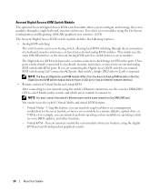
... which server module to connect to. This switch uses the same OSCAR interface as the Avocent Analog KVM switch to a remote diskette, optical drive, or USB key. NOTE: The Avocent Digital Access KVM module differs from any location, using the switch's Ethernet connection, use the switch's Virtual Media and virtual KVM...
... which server module to connect to. This switch uses the same OSCAR interface as the Avocent Analog KVM switch to a remote diskette, optical drive, or USB key. NOTE: The Avocent Digital Access KVM module differs from any location, using the switch's Ethernet connection, use the switch's Virtual Media and virtual KVM...

Hardware Owner's Manual (PDF)
Page 36
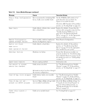
The following DIMM is electrically isolated: DIMM x. See "Troubleshooting Server Module Memory" on page 105. Faulty or improperly connected Replace the diskette. See "Troubleshooting USB Devices" on page 112. Replace the diskette. If the problem persists, see "Troubleshooting Server Module Memory" on page 78. Drive not ready Diskette missing or ... slot 1. Mismatched or unmatched DIMMs installed; Server Module Messages (continued) Message Causes Corrective Actions DIMMs must be populated in size, speed, and technology. See "Troubleshooting USB Devices" on page 78.
The following DIMM is electrically isolated: DIMM x. See "Troubleshooting Server Module Memory" on page 105. Faulty or improperly connected Replace the diskette. See "Troubleshooting USB Devices" on page 112. Replace the diskette. If the problem persists, see "Troubleshooting Server Module Memory" on page 78. Drive not ready Diskette missing or ... slot 1. Mismatched or unmatched DIMMs installed; Server Module Messages (continued) Message Causes Corrective Actions DIMMs must be populated in size, speed, and technology. See "Troubleshooting USB Devices" on page 78.
Hardware Owner's Manual (PDF)
Page 39
... could not implement Retry Remote Configuration. If the problem persists, see "Getting Help" on page 127. Memory sparing enabled. About Your System 39 See "Troubleshooting USB Devices" on page 105 or "Troubleshooting Hard Drives" on page 112. Replace the diskette. See "Troubleshooting Server Module Memory" on page 113. faulty Check the...
... could not implement Retry Remote Configuration. If the problem persists, see "Getting Help" on page 127. Memory sparing enabled. About Your System 39 See "Troubleshooting USB Devices" on page 105 or "Troubleshooting Hard Drives" on page 112. Replace the diskette. See "Troubleshooting Server Module Memory" on page 113. faulty Check the...
Hardware Owner's Manual (PDF)
Page 40
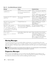
...section. Replace a microprocessor so that section for a BIOS update using the Dell Support website at support.dell.com. There is no ). Ensure that accompanied the operating system or application. See "Troubleshooting USB Devices" on page 105 or "Troubleshooting Hard Drives" on page 84. ...Diagnostics Messages When you may result. Warning! No microcode update loaded for a BIOS update using the Dell Support website at support.dell.com. not recommended by the...
...section. Replace a microprocessor so that section for a BIOS update using the Dell Support website at support.dell.com. There is no ). Ensure that accompanied the operating system or application. See "Troubleshooting USB Devices" on page 105 or "Troubleshooting Hard Drives" on page 84. ...Diagnostics Messages When you may result. Warning! No microcode update loaded for a BIOS update using the Dell Support website at support.dell.com. not recommended by the...
Hardware Owner's Manual (PDF)
Page 46
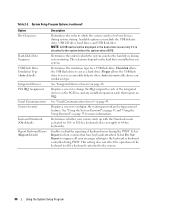
...affect the operation of keyboard errors during system startup. System Setup Program Options (continued) Option Boot Sequence Hard-Disk Drive Sequence USB Flash Drive Emulation Type (Auto default) Integrated Devices PCI IRQ Assignment Serial Communication System Security Keyboard NumLock (On default) Report Keyboard...with the NumLock mode activated on page 48. Determines whether your system. Available options can include the USB diskette drive, USB CD drive, hard drives, and USB flash drive. The selections depend on the hard drives installed in which the system searches for more...
...affect the operation of keyboard errors during system startup. System Setup Program Options (continued) Option Boot Sequence Hard-Disk Drive Sequence USB Flash Drive Emulation Type (Auto default) Integrated Devices PCI IRQ Assignment Serial Communication System Security Keyboard NumLock (On default) Report Keyboard...with the NumLock mode activated on page 48. Determines whether your system. Available options can include the USB diskette drive, USB CD drive, hard drives, and USB flash drive. The selections depend on the hard drives installed in which the system searches for more...
Hardware Owner's Manual (PDF)
Page 48
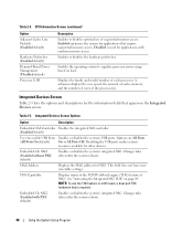
...the System Setup Program Integrated Devices Screen Options Option Description Embedded SAS Controller Enables the integrated SAS controller. (Enabled default) User Accessible USB Ports Enables or disables the system's USB ports. Changes take effect after the system reboots. Embedded Gb NIC2 (Enabled with random memory access. Enabled optimizes the system for the... Screen Table 2-5 lists the options and descriptions for applications that appear on load. See "Activating the Integrated NIC TOE" on page 84. Disabling the USB ports makes system resources available for NIC1.
...the System Setup Program Integrated Devices Screen Options Option Description Embedded SAS Controller Enables the integrated SAS controller. (Enabled default) User Accessible USB Ports Enables or disables the system's USB ports. Changes take effect after the system reboots. Embedded Gb NIC2 (Enabled with random memory access. Enabled optimizes the system for the... Screen Table 2-5 lists the options and descriptions for applications that appear on load. See "Activating the Integrated NIC TOE" on page 84. Disabling the USB ports makes system resources available for NIC1.


