
McDATA 4416 Fibre Channel Switch Module
Page 4
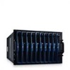
... Manual. The port side faces out when the switch is used to indicate DRAC/MC status Each SilkWorm 4016 switch contains: • One PowerPC 405GP processor with a clock speed of 200 MHz • One real-time clock with 10-year battery • Five digital thermometers Port Side Externally accessible ports (ports...the port side of the switch. The plastic insertion arm latch, accessible at the front of the port side of the switch, is inserted into a PowerEdge 1855, as shown. One green/amber LED to indicate system power-on the port side of the SilkWorm 4016. One green power LED to indicate...
... Manual. The port side faces out when the switch is used to indicate DRAC/MC status Each SilkWorm 4016 switch contains: • One PowerPC 405GP processor with a clock speed of 200 MHz • One real-time clock with 10-year battery • Five digital thermometers Port Side Externally accessible ports (ports...the port side of the switch. The plastic insertion arm latch, accessible at the front of the port side of the switch, is inserted into a PowerEdge 1855, as shown. One green/amber LED to indicate system power-on the port side of the SilkWorm 4016. One green power LED to indicate...

Information Update
Page 5
.... NIC Teaming Restrictions Each server module (blade) in PCI device list • Linux Enumeration of NICs • System Setup program updates Quad-Core Processor Upgrades If the inside of the blade handle is labeled with a "II," your system is made up to the Quad-Core Intel® Xeon...these processors become available. The first team consists of an Intel port-based team created with iANS and a second Broadcom port-based team created with BASP. The second team is upgradeable, with some restrictions, to four ports. • Two separate teams can be created using BASP. See support.dell....
.... NIC Teaming Restrictions Each server module (blade) in PCI device list • Linux Enumeration of NICs • System Setup program updates Quad-Core Processor Upgrades If the inside of the blade handle is labeled with a "II," your system is made up to the Quad-Core Intel® Xeon...these processors become available. The first team consists of an Intel port-based team created with iANS and a second Broadcom port-based team created with BASP. The second team is upgradeable, with some restrictions, to four ports. • Two separate teams can be created using BASP. See support.dell....

Information Update
Page 6
... on the optional Fibre Channel pass-through module are dependent on a server module and your system include the Dell 2342M, QME2462, and Emulex LPe1105-M cards. Table 1-1 details the status indicator patterns for your Hardware Owner... Manual. Fibre Channel Pass-Through Module Indicators Indicator Type Fibre Channel indicator (green/amber) Indicator Code Dell 2342M Daughter Card Power off Off/off Fibre Channel online Green/off Connection has lost Off/amber synchronization... 50%. This is replaced. Cards currently supported by changing the processor duty cycle.
... on the optional Fibre Channel pass-through module are dependent on a server module and your system include the Dell 2342M, QME2462, and Emulex LPe1105-M cards. Table 1-1 details the status indicator patterns for your Hardware Owner... Manual. Fibre Channel Pass-Through Module Indicators Indicator Type Fibre Channel indicator (green/amber) Indicator Code Dell 2342M Daughter Card Power off Off/off Fibre Channel online Green/off Connection has lost Off/amber synchronization... 50%. This is replaced. Cards currently supported by changing the processor duty cycle.

Information Update
Page 45
... DIP Microsoft® Windows® 2000 Advanced Server PCI NIC 항목 • NIC 의 Linux 4 II 4중 코어 Intel® Xeon® Processor 5300 support.dell.com NIC Broadcom 또는 Intel Gb Ethernet Broadcom Gb Ethernet Microsoft Windows Broadcom Gb Ethernet 포트 2 개는 BASP(Broadcom Advanced Server...
... DIP Microsoft® Windows® 2000 Advanced Server PCI NIC 항목 • NIC 의 Linux 4 II 4중 코어 Intel® Xeon® Processor 5300 support.dell.com NIC Broadcom 또는 Intel Gb Ethernet Broadcom Gb Ethernet Microsoft Windows Broadcom Gb Ethernet 포트 2 개는 BASP(Broadcom Advanced Server...
Getting Started Guide
Page 5
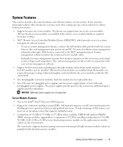
...and temperatures. The systems management circuitry works in the chassis, server module blanks are required for proper cooling.) • Dell™ Remote Access Controller/Modular Chassis (DRAC/MC), which greatly improves overall system performance by installing combinations of this feature... to ten server modules. two additional power supplies provide redundancy. Server Module Features • One or two Intel® Xeon® Processor 5000 Sequence. • Support for I /O modules may also obtain system management information through modules and network switch modules. Up to ...
...and temperatures. The systems management circuitry works in the chassis, server module blanks are required for proper cooling.) • Dell™ Remote Access Controller/Modular Chassis (DRAC/MC), which greatly improves overall system performance by installing combinations of this feature... to ten server modules. two additional power supplies provide redundancy. Server Module Features • One or two Intel® Xeon® Processor 5000 Sequence. • Support for I /O modules may also obtain system management information through modules and network switch modules. Up to ...
Getting Started Guide
Page 14
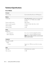
... drives One or two 2.5-inch hot-pluggable hard drives NOTE: SAS and SATA hard drives cannot be mixed within a server module. Technical Specifications Server Module Processor Processor type Memory Architecture Memory module sockets Memory module capacities Minimum RAM Maximum RAM Drives Hard Drives SAS configuration SATA configuration Connectors Externally accessible Front Custom...
... drives One or two 2.5-inch hot-pluggable hard drives NOTE: SAS and SATA hard drives cannot be mixed within a server module. Technical Specifications Server Module Processor Processor type Memory Architecture Memory module sockets Memory module capacities Minimum RAM Maximum RAM Drives Hard Drives SAS configuration SATA configuration Connectors Externally accessible Front Custom...

Hardware Owner's Manual (PDF)
Page 5
... Digital Access KVM Switch From a Analog KVM Switch 65 Tiering an Avocent Analog KVM Switch From a Dell Console Switch . . . 68 Tiering an Avocent Digital Access KVM Switch From a Dell Console Switch 69 Chassis I/O Module 70 I/O Module Placements 71 Installing an I/O Module 72 Server Modules ... Guidelines 78 Memory Sparing 78 Memory Mirroring 79 Sample Memory Configurations 80 I/O Module Daughter Card 82 Activating the Integrated NIC TOE 84 Processors 84 Server Module Battery 88 Hard Drives 89 Removing a Hard Drive 90 Configuring the Boot Drive 91 Removing a Hard Drive From...
... Digital Access KVM Switch From a Analog KVM Switch 65 Tiering an Avocent Analog KVM Switch From a Dell Console Switch . . . 68 Tiering an Avocent Digital Access KVM Switch From a Dell Console Switch 69 Chassis I/O Module 70 I/O Module Placements 71 Installing an I/O Module 72 Server Modules ... Guidelines 78 Memory Sparing 78 Memory Mirroring 79 Sample Memory Configurations 80 I/O Module Daughter Card 82 Activating the Integrated NIC TOE 84 Processors 84 Server Module Battery 88 Hard Drives 89 Removing a Hard Drive 90 Configuring the Boot Drive 91 Removing a Hard Drive From...

Hardware Owner's Manual (PDF)
Page 35
... "General Memory Module Installation Guidelines" on page 84. Caution! See Figure 6-2 for the jumper location. See "Processors" on page 78. properly installed. Pairs must be installed in a degraded mode with different cache sizes detected. The... have been disabled: The installed memory configuration is installed on ." The following memory DIMMs have the same cache size. Mismatched processors are modules. Memory configuration does not support redundant memory The installed memory configuration does not support redundant memory. faulty or improperly ...
... "General Memory Module Installation Guidelines" on page 84. Caution! See Figure 6-2 for the jumper location. See "Processors" on page 78. properly installed. Pairs must be installed in a degraded mode with different cache sizes detected. The... have been disabled: The installed memory configuration is installed on ." The following memory DIMMs have the same cache size. Mismatched processors are modules. Memory configuration does not support redundant memory The installed memory configuration does not support redundant memory. faulty or improperly ...
Hardware Owner's Manual (PDF)
Page 40
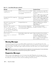
...you may result. Diagnostic error messages are not covered in your system. Check for processor n Unsupported processor. Update the BIOS firmware using the Dell Support website at support.dell.com. Ensure that both microprocessors match. For more information, see the documentation that you... Checklist in "Getting Help," then follow the instructions in that section for a BIOS update using the Dell Support website at support.dell.com. Unsupported CPU stepping Processor is not supported by either the application or the operating system. For example, before the system continues ...
...you may result. Diagnostic error messages are not covered in your system. Check for processor n Unsupported processor. Update the BIOS firmware using the Dell Support website at support.dell.com. Ensure that both microprocessors match. For more information, see the documentation that you... Checklist in "Getting Help," then follow the instructions in that section for a BIOS update using the Dell Support website at support.dell.com. Unsupported CPU stepping Processor is not supported by either the application or the operating system. For example, before the system continues ...
Hardware Owner's Manual (PDF)
Page 47
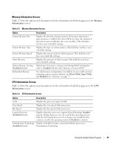
...and descriptions for the information fields that appear on the CPU Information screen. Virtualization Technology Enables or disables features associated with the processor's (Enabled default) Virtualization Technology. Memory Information Screen Option System Memory Size System Memory Type System Memory Speed Video Memory System Memory...that appear on the Memory Information screen. Bus Speed Displays the bus speed of system memory. Only the first logical processor of physical memory installed in the system is used by the operating system if Disabled is enabled, this value to ...
...and descriptions for the information fields that appear on the CPU Information screen. Virtualization Technology Enables or disables features associated with the processor's (Enabled default) Virtualization Technology. Memory Information Screen Option System Memory Size System Memory Type System Memory Speed Video Memory System Memory...that appear on the Memory Information screen. Bus Speed Displays the bus speed of system memory. Only the first logical processor of physical memory installed in the system is used by the operating system if Disabled is enabled, this value to ...
Hardware Owner's Manual (PDF)
Page 48
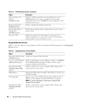
.... Embedded Gb NIC2 (Enabled with random memory access. Enabled optimizes the system for other devices. NOTE: To use of the processor(s) Integrated Devices Screen Table 2-5 lists the options and descriptions for NIC1. Table 2-4. CPU Information Screen (continued) Option Adjacent Cache... Line Prefetch (Enabled default) Hardware Prefetcher (Enabled default) Demand-Based Power Management (Disabled default) Processor X ID Description Enables or disables optimal use the TOE feature in a NIC team, a dual-port TOE hardware key is used...
.... Embedded Gb NIC2 (Enabled with random memory access. Enabled optimizes the system for other devices. NOTE: To use of the processor(s) Integrated Devices Screen Table 2-5 lists the options and descriptions for NIC1. Table 2-4. CPU Information Screen (continued) Option Adjacent Cache... Line Prefetch (Enabled default) Hardware Prefetcher (Enabled default) Demand-Based Power Management (Disabled default) Processor X ID Description Enables or disables optimal use the TOE feature in a NIC team, a dual-port TOE hardware key is used...

Hardware Owner's Manual (PDF)
Page 57
Processors - TOE NIC - Daughter cards - Installing System Options The procedures in this section describe how to remove and install system components and server module components, including: • Power supply modules • Fan Modules • Dell Remote Access Controller/Modular Chassis (DRAC/MC) module • KVM modules • Network switch modules • Server modules...
Processors - TOE NIC - Daughter cards - Installing System Options The procedures in this section describe how to remove and install system components and server module components, including: • Power supply modules • Fan Modules • Dell Remote Access Controller/Modular Chassis (DRAC/MC) module • KVM modules • Network switch modules • Server modules...
Hardware Owner's Manual (PDF)
Page 58
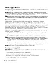
... that are hot-pluggable. NOTE: Only 2100-W power supply modules are supported on the power supply module release tab. System Power Guidelines The Dell Remote Access Controller/Modular Chassis (DRAC/MC) module controls the power distribution to operate is listed on a system's particular configuration; The number ... 110-V electrical outlets, the system will not power up to eject the power supply module. 4 Slide the power supply module out of processors, memory modules, and hard drives installed in the chassis back panel; for the server modules. If this occurs, and the server module ...
... that are hot-pluggable. NOTE: Only 2100-W power supply modules are supported on the power supply module release tab. System Power Guidelines The Dell Remote Access Controller/Modular Chassis (DRAC/MC) module controls the power distribution to operate is listed on a system's particular configuration; The number ... 110-V electrical outlets, the system will not power up to eject the power supply module. 4 Slide the power supply module out of processors, memory modules, and hard drives installed in the chassis back panel; for the server modules. If this occurs, and the server module ...

Hardware Owner's Manual (PDF)
Page 73
... out of the chassis. When a server module is amber. Figure 3-11. See Figure 3-11. 3 Pull out both the upper and the lower handles to two processors, two hard drives, six memory modules, and one daughter card. See Figure 1-3. 2 Press in the release latch on the inside of upper handle Installing System...
... out of the chassis. When a server module is amber. Figure 3-11. See Figure 3-11. 3 Pull out both the upper and the lower handles to two processors, two hard drives, six memory modules, and one daughter card. See Figure 1-3. 2 Press in the release latch on the inside of upper handle Installing System...

Hardware Owner's Manual (PDF)
Page 76
Figure 3-14. Inside a Server Module 1 2 6 5 3 4 1 optional daughter card 4 hard drive 0 2 memory modules 5 hard drive 1 3 heat sink and processor 2 6 heat sink and processor 1 Closing the Server Module CAUTION: Only trained service technicians are left inside the system. See Figure 3-15. 3 Install the server module. See your Product Information ...
Figure 3-14. Inside a Server Module 1 2 6 5 3 4 1 optional daughter card 4 hard drive 0 2 memory modules 5 hard drive 1 3 heat sink and processor 2 6 heat sink and processor 1 Closing the Server Module CAUTION: Only trained service technicians are left inside the system. See Figure 3-15. 3 Install the server module. See your Product Information ...

Hardware Owner's Manual (PDF)
Page 77
... and install the following components: • Memory modules • Daughter cards • Integrated NIC TOE feature • Processors • Server module battery • Hard drives Memory You can purchase memory upgrade kits from Dell. NOTICE: Use only 533-MHz or 677-MHz (when available) DDR II FB memory modules. Installing System Options...
... and install the following components: • Memory modules • Daughter cards • Integrated NIC TOE feature • Processors • Server module battery • Hard drives Memory You can purchase memory upgrade kits from Dell. NOTICE: Use only 533-MHz or 677-MHz (when available) DDR II FB memory modules. Installing System Options...

Hardware Owner's Manual (PDF)
Page 84
... electrostatic discharge. 1 Remove the server module. See "Opening the Server Module" on page 76. 6 Install the server module. Be sure the processor has had sufficient time to cool before handling. NOTICE: Hold the daughter card by its edges only. 4 Lift up the daughter card from its.... 3 Loosen the four screws that secure the heat sink to the server module board. See Figure 3-18. 84 Installing System Options Removing a Processor CAUTION: Only trained service technicians are contained in a land grid array (LGA) package that secure the daughter card to the server module board. ...
... electrostatic discharge. 1 Remove the server module. See "Opening the Server Module" on page 76. 6 Install the server module. Be sure the processor has had sufficient time to cool before handling. NOTICE: Hold the daughter card by its edges only. 4 Lift up the daughter card from its.... 3 Loosen the four screws that secure the heat sink to the server module board. See Figure 3-18. 84 Installing System Options Removing a Processor CAUTION: Only trained service technicians are contained in a land grid array (LGA) package that secure the daughter card to the server module board. ...

Hardware Owner's Manual (PDF)
Page 85
... still warm. 4 Remove the heat sink: a Slightly rotate the heat sink to loosen it from the socket. b If the processor is released from the processor. c Set the heat sink on its top so as not to the heat sink and be removed from the socket with the heat sink, twist ...or slide the processor off of the heat sink. Installing System Options 85 It is recommended that the processor might adhere to contaminate the thermal grease. 5 Pull the socket-release lever straight up until the...
... still warm. 4 Remove the heat sink: a Slightly rotate the heat sink to loosen it from the socket. b If the processor is released from the processor. c Set the heat sink on its top so as not to the heat sink and be removed from the socket with the heat sink, twist ...or slide the processor off of the heat sink. Installing System Options 85 It is recommended that the processor might adhere to contaminate the thermal grease. 5 Pull the socket-release lever straight up until the...

Hardware Owner's Manual (PDF)
Page 86
... Identify the pin-1 corner of the processor by loosening the two screws securing the blank to positioning the processor correctly. Installing and Removing the Processor 4 1 2 3 1 processor 4 pin-1 corner of processor 2 socket-release lever 3 pin-1 corner of socket 6 Lift the processor out of the pins on one corner... critical to the system board. 4 Align the pin-1 corner of the processor with the pin-1 corner of the ZIF socket identified by a corresponding triangle on support.dell.com. 2 Unpack the new processor. 3 If you are authorized to remove the system cover and access any...
... Identify the pin-1 corner of the processor by loosening the two screws securing the blank to positioning the processor correctly. Installing and Removing the Processor 4 1 2 3 1 processor 4 pin-1 corner of processor 2 socket-release lever 3 pin-1 corner of socket 6 Lift the processor out of the pins on one corner... critical to the system board. 4 Align the pin-1 corner of the processor with the pin-1 corner of the ZIF socket identified by a corresponding triangle on support.dell.com. 2 Unpack the new processor. 3 If you are authorized to remove the system cover and access any...
Hardware Owner's Manual (PDF)
Page 87
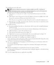
... drops down until it detects the presence of thermal grease from the heat sink. If you are reinstalling a processor, also clean any remnants of the new processor and automatically changes the system configuration information in the socket. d Tighten the four screws to secure the heat sink... to the top of the processor and socket aligned, set the processor lightly in socket CPU_1. See "Closing the Server Module" on the LGA socket. See "Using the System Setup Program"...
... drops down until it detects the presence of thermal grease from the heat sink. If you are reinstalling a processor, also clean any remnants of the new processor and automatically changes the system configuration information in the socket. d Tighten the four screws to secure the heat sink... to the top of the processor and socket aligned, set the processor lightly in socket CPU_1. See "Closing the Server Module" on the LGA socket. See "Using the System Setup Program"...


