Hardware Maintenance Manual
Page 3
Table of Contents Preface ...iii Audience ...iii Organization ...iii Overview of Dell EqualLogic Products ...iii Related Documentation ...v Technical Support and Customer Service ...v ... and Turning Off Power to an Array 1-13 Returning Hardware ...1-14 2 Maintaining Disk Drives...2-1 Disk Drive LEDs...2-1 Disk Drive Status ...2-2 Disk Drive Numbering ...2-3 Array Behavior When a Disk Drive Fails ...2-3 Disk Drive Requirements ...2-4 Removing Disk Drives ...2-4 Installing Disk Drives...2-7 3 Maintaining Control Modules...3-1 Identifying the Control Module...3-1 Interpreting Control Module LEDs ...
Table of Contents Preface ...iii Audience ...iii Organization ...iii Overview of Dell EqualLogic Products ...iii Related Documentation ...v Technical Support and Customer Service ...v ... and Turning Off Power to an Array 1-13 Returning Hardware ...1-14 2 Maintaining Disk Drives...2-1 Disk Drive LEDs...2-1 Disk Drive Status ...2-2 Disk Drive Numbering ...2-3 Array Behavior When a Disk Drive Fails ...2-3 Disk Drive Requirements ...2-4 Removing Disk Drives ...2-4 Installing Disk Drives...2-7 3 Maintaining Control Modules...3-1 Identifying the Control Module...3-1 Interpreting Control Module LEDs ...
Hardware Maintenance Manual
Page 5
... of Dell EqualLogic Products Thank you will find them intuitive and simple to have extensive network or storage system experience. Organization This manual is organized as follows: • Chapter 1, Basic Array Information, describes the PS6500 array front and back panels and technical specifications, in addition to basic array operations. • Chapter 2, Maintaining Disk Drives...
... of Dell EqualLogic Products Thank you will find them intuitive and simple to have extensive network or storage system experience. Organization This manual is organized as follows: • Chapter 1, Basic Array Information, describes the PS6500 array front and back panels and technical specifications, in addition to basic array operations. • Chapter 2, Maintaining Disk Drives...
Hardware Maintenance Manual
Page 9
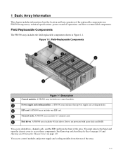
... operations, and how to access these components. A PS6500 array includes 48 disk drives. Figure 1-1: Field-Replaceable Components Figure 1-1 Description Control modules. A PS6500 array includes one EIP card. Field Replaceable Components The PS6500 array includes the field-replaceable components shown in a PS6500 storage array, technical specifications, power on page 1-9. A PS6500 array includes three power supply and cooling modules...
... operations, and how to access these components. A PS6500 array includes 48 disk drives. Figure 1-1: Field-Replaceable Components Figure 1-1 Description Control modules. A PS6500 array includes one EIP card. Field Replaceable Components The PS6500 array includes the field-replaceable components shown in a PS6500 storage array, technical specifications, power on page 1-9. A PS6500 array includes three power supply and cooling modules...
Hardware Maintenance Manual
Page 10
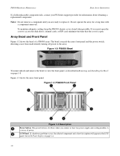
PS6500 Hardware Maintenance Basic Array Information If a field-replaceable component fails, contact your PS Series support provider for a long time with a component removed. Notes: Do not remove a component until you are ready to access the disk drives, channel cards, or EIP card, minimize the time that the cover is lit ...(blue) when you must unlock and remove the bezel to view the front panel, as described in the LCD panel. To maintain adequate cooling, keep the PS6500 chassis cover closed ...
PS6500 Hardware Maintenance Basic Array Information If a field-replaceable component fails, contact your PS Series support provider for a long time with a component removed. Notes: Do not remove a component until you are ready to access the disk drives, channel cards, or EIP card, minimize the time that the cover is lit ...(blue) when you must unlock and remove the bezel to view the front panel, as described in the LCD panel. To maintain adequate cooling, keep the PS6500 chassis cover closed ...
Hardware Maintenance Manual
Page 11
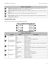
.... The two cam screws secure the array front panel to pull out the chassis, opening the cover and exposing the disk drives, channel cards, and EIP card. Figure 1-4: PS6500 Hardware Status LEDs Figure 1-4 Description Indicator Status Description Array power Off No power. Orange Power supply failure, fan failure, or upper or lower temperature...
.... The two cam screws secure the array front panel to pull out the chassis, opening the cover and exposing the disk drives, channel cards, and EIP card. Figure 1-4: PS6500 Hardware Status LEDs Figure 1-4 Description Indicator Status Description Array power Off No power. Orange Power supply failure, fan failure, or upper or lower temperature...

Hardware Maintenance Manual
Page 12
... any numerical identifier for the affected component appear in the LCD panel. Yellow EIP card failure. Disk Drive Failure If multiple hardware failures occur simultaneously, the LCD panel displays multiple icons and descriptions. Figure 1-5: LCD Panel - PS6500 Hardware Maintenance Basic Array Information Indicator EIP card Figure 1-4 Description (Continued) Status Description Off Normal operation...
... any numerical identifier for the affected component appear in the LCD panel. Yellow EIP card failure. Disk Drive Failure If multiple hardware failures occur simultaneously, the LCD panel displays multiple icons and descriptions. Figure 1-5: LCD Panel - PS6500 Hardware Maintenance Basic Array Information Indicator EIP card Figure 1-4 Description (Continued) Status Description Off Normal operation...
Hardware Maintenance Manual
Page 13
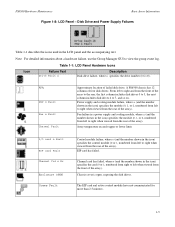
...n (and the number shown in the LCD panel and the accompanying text. Chassis cover is open, exposing the disk drives. A PS6500 chassis has 12 columns of failed disk drive. Power supply and cooling module failure, where n (and the number shown in the icon) specifies the control module... have not communicated for more than 2.5 minutes. 1-5 Icon Table 1-1: LCD Panel Hardware Icons Failure Text Drive Fault n Description Disk drive failure, where n specifies the drive number (0 to view the group event log. PS6500 Hardware Maintenance Basic Array Information Figure 1-8: LCD Panel -
...n (and the number shown in the LCD panel and the accompanying text. Chassis cover is open, exposing the disk drives. A PS6500 chassis has 12 columns of failed disk drive. Power supply and cooling module failure, where n (and the number shown in the icon) specifies the control module... have not communicated for more than 2.5 minutes. 1-5 Icon Table 1-1: LCD Panel Hardware Icons Failure Text Drive Fault n Description Disk drive failure, where n specifies the drive number (0 to view the group event log. PS6500 Hardware Maintenance Basic Array Information Figure 1-8: LCD Panel -
Hardware Maintenance Manual
Page 14
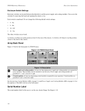
... operation. Each switch is in the position closest to the rear of the chassis. Control modules. See Figure 1-10. 1-6 PS6500 Hardware Maintenance Basic Array Information Enclosure Switch Settings Enclosure switches are not used. Do not change the following default switch settings: &#...PS6500 array. Off • 11 - You access the switches by removing the bezel and opening the chassis cover. Figure 1-9: PS6500 Back Panel Figure 1-9 Description Power supply and cooling modules. Three modules must be installed to right. On The other switches are located between the disk drives...
... operation. Each switch is in the position closest to the rear of the chassis. Control modules. See Figure 1-10. 1-6 PS6500 Hardware Maintenance Basic Array Information Enclosure Switch Settings Enclosure switches are not used. Do not change the following default switch settings: &#...PS6500 array. Off • 11 - You access the switches by removing the bezel and opening the chassis cover. Figure 1-9: PS6500 Back Panel Figure 1-9 Description Power supply and cooling modules. Three modules must be installed to right. On The other switches are located between the disk drives...
Hardware Maintenance Manual
Page 15
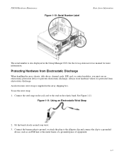
.... Fit the band closely around your wrist. 3. PS6500 Hardware Maintenance Figure 1-10: Serial Number Label Basic Array Information The serial number is also displayed in the array shipping box. Always store hardware where it is protected from Electrostatic Discharge When handling the array chassis, disk drives, channel cards, EIP card, or control modules...
.... Fit the band closely around your wrist. 3. PS6500 Hardware Maintenance Figure 1-10: Serial Number Label Basic Array Information The serial number is also displayed in the array shipping box. Always store hardware where it is protected from Electrostatic Discharge When handling the array chassis, disk drives, channel cards, EIP card, or control modules...

Hardware Maintenance Manual
Page 17
... left side of the array, use a flathead screwdriver to the chassis. PS6500 Hardware Maintenance Basic Array Information Figure 1-14: Detaching the Bezel from the Chassis To install and lock the bezel: 1. Opening and Closing the Chassis Cover To access disk drives, channel cards, and the EIP card, you must remove the bezel, then...
... left side of the array, use a flathead screwdriver to the chassis. PS6500 Hardware Maintenance Basic Array Information Figure 1-14: Detaching the Bezel from the Chassis To install and lock the bezel: 1. Opening and Closing the Chassis Cover To access disk drives, channel cards, and the EIP card, you must remove the bezel, then...

Hardware Maintenance Manual
Page 18
...-loop fasteners. • One wire assembly has one arm, two clamps, and three fabric hook-and-loop fasteners. It also enables you , exposing the disk drives. See Figure 1-16. 1-10 Use a flathead screwdriver to reduce the risk of the front panel clockwise. PS6500 Hardware Maintenance Figure 1-15: Opening the Chassis Basic Array Information 2.
...-loop fasteners. • One wire assembly has one arm, two clamps, and three fabric hook-and-loop fasteners. It also enables you , exposing the disk drives. See Figure 1-16. 1-10 Use a flathead screwdriver to reduce the risk of the front panel clockwise. PS6500 Hardware Maintenance Figure 1-15: Opening the Chassis Basic Array Information 2.

Hardware Maintenance Manual
Page 23
... (12 sets of four) is visible with the bezel on. These LEDs are several LEDs on a PS6500 array that indicate the status of disk drives: • On the bottom front of the array, in the center, the disk hardware status LED (circled in Figure 2-1) shows the overall status of Front Panel Each LED corresponds...
... (12 sets of four) is visible with the bezel on. These LEDs are several LEDs on a PS6500 array that indicate the status of disk drives: • On the bottom front of the array, in the center, the disk hardware status LED (circled in Figure 2-1) shows the overall status of Front Panel Each LED corresponds...

Hardware Maintenance Manual
Page 24
... 2-2. Color Off Yellow Flashing yellow Description Normal operation. Normal operation. PS6500 Hardware Maintenance Figure 2-3: Disk LED Maintaining Disk Drives Table 2-1 explains how to interpret the LEDs that indicate disk status. Disk Drive Status You can identify a disk drive failure by: • LEDs. Table 2-1: PS6500 Disk Drive Status LED Descriptions LED Location Disks LED on the LCD panel (located behind bezel). Normal condition or...
... 2-2. Color Off Yellow Flashing yellow Description Normal operation. Normal operation. PS6500 Hardware Maintenance Figure 2-3: Disk LED Maintaining Disk Drives Table 2-1 explains how to interpret the LEDs that indicate disk status. Disk Drive Status You can identify a disk drive failure by: • LEDs. Table 2-1: PS6500 Disk Drive Status LED Descriptions LED Location Disks LED on the LCD panel (located behind bezel). Normal condition or...
Hardware Maintenance Manual
Page 25
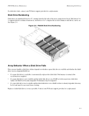
... of disk drives, and so on whether a spare disk drive is available and whether the failed drive was in a degraded RAID set. • If a spare disk drive is in a RAID set with no previous disk drive failure, the RAID set becomes degraded. Replace a failed disk drive as soon as possible. Figure 2-4: PS6500 Disk Drive Numbering Array Behavior When a Disk Drive Fails How an array handles a disk drive failure...
... of disk drives, and so on whether a spare disk drive is available and whether the failed drive was in a degraded RAID set. • If a spare disk drive is in a RAID set with no previous disk drive failure, the RAID set becomes degraded. Replace a failed disk drive as soon as possible. Figure 2-4: PS6500 Disk Drive Numbering Array Behavior When a Disk Drive Fails How an array handles a disk drive failure...
Hardware Maintenance Manual
Page 26
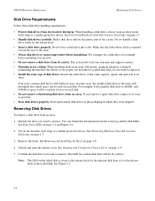
... information from electrostatic discharge. See Protecting Hardware from an array. Remove the bezel. PS6500 Hardware Maintenance Maintaining Disk Drives Disk Drive Requirements Follow these disk drive handling requirements: • Protect disk drives from the event log and the disk LEDs. Do not force a disk drive into a slot. Identify the drive you want to the release latch for use on page 1-8. 4. For example, let...
... information from electrostatic discharge. See Protecting Hardware from an array. Remove the bezel. PS6500 Hardware Maintenance Maintaining Disk Drives Disk Drive Requirements Follow these disk drive handling requirements: • Protect disk drives from the event log and the disk LEDs. Do not force a disk drive into a slot. Identify the drive you want to the release latch for use on page 1-8. 4. For example, let...

Hardware Maintenance Manual
Page 27
This will disengage the disk drive from the slot. 7. Wait 30 seconds to allow the disk drive to stop spinning and the heads to land. 2-5 Open the disk drive release lever by sliding the latch toward the front of the array and pulling up the latch arm. PS6500 Hardware Maintenance Maintaining Disk Drives Figure 2-5: Identifying and Removing the Correct Drive 6.
This will disengage the disk drive from the slot. 7. Wait 30 seconds to allow the disk drive to stop spinning and the heads to land. 2-5 Open the disk drive release lever by sliding the latch toward the front of the array and pulling up the latch arm. PS6500 Hardware Maintenance Maintaining Disk Drives Figure 2-5: Identifying and Removing the Correct Drive 6.

Hardware Maintenance Manual
Page 28
Maintaining Disk Drives Caution: Do not pull the drive up and remove the drive from the slot. Holding the sides of the disk drive, pull up by the lever. Figure 2-6: Wrong Way to Hold a Disk Drive 2-6 PS6500 Hardware Maintenance 8. See Figure 2-6.
Maintaining Disk Drives Caution: Do not pull the drive up and remove the drive from the slot. Holding the sides of the disk drive, pull up by the lever. Figure 2-6: Wrong Way to Hold a Disk Drive 2-6 PS6500 Hardware Maintenance 8. See Figure 2-6.

Hardware Maintenance Manual
Page 29
... toward the front of the array (where the power supplies and control modules are). Installing Disk Drives To install a disk drive in which the replacement drive was shipped. Contact your PS Series support provider for information about returning hardware. Use an electrostatic...chassis cover. Hold the replacement disk drive by sliding the latch toward the rear of the array and lifting up the latch arm. See Protecting Hardware from Electrostatic Discharge on page 1-9. 4. PS6500 Hardware Maintenance Maintaining Disk Drives Return the failed drive in the packaging in an ...
... toward the front of the array (where the power supplies and control modules are). Installing Disk Drives To install a disk drive in which the replacement drive was shipped. Contact your PS Series support provider for information about returning hardware. Use an electrostatic...chassis cover. Hold the replacement disk drive by sliding the latch toward the rear of the array and lifting up the latch arm. See Protecting Hardware from Electrostatic Discharge on page 1-9. 4. PS6500 Hardware Maintenance Maintaining Disk Drives Return the failed drive in the packaging in an ...

Hardware Maintenance Manual
Page 30
Push the disk drive the rest of the way into the slot until you feel resistance (2). The lever should still be open. e. Pull back the latch (4). 2-8 PS6500 Hardware Maintenance Maintaining Disk Drives c. Do not force the lever closed can break the latch and make the drive unusable. Caution: Forcing the lever closed (3). Slide the replacement disk drive gently into place. d.
Push the disk drive the rest of the way into the slot until you feel resistance (2). The lever should still be open. e. Pull back the latch (4). 2-8 PS6500 Hardware Maintenance Maintaining Disk Drives c. Do not force the lever closed can break the latch and make the drive unusable. Caution: Forcing the lever closed (3). Slide the replacement disk drive gently into place. d.

Hardware Maintenance Manual
Page 31
See Opening and Closing the Chassis Cover on page 2-2 for more information. 2-9 Reinstall the bezel. Make sure the new disk drive is fully seated and flush with the slot in the drive carrier (7). 9. Close and lock the chassis cover. h. Make sure it engages with the other drives (5). See Disk Drive Status on page 1-9. 10. Keep holding the latch open , lower the lever until the drive is operational. Push the latch forward (6). g. See Removing and Installing the Bezel on page 1-8. Holding the latch open . PS6500 Hardware Maintenance Maintaining Disk Drives f.
See Opening and Closing the Chassis Cover on page 2-2 for more information. 2-9 Reinstall the bezel. Make sure the new disk drive is fully seated and flush with the slot in the drive carrier (7). 9. Close and lock the chassis cover. h. Make sure it engages with the other drives (5). See Disk Drive Status on page 1-9. 10. Keep holding the latch open , lower the lever until the drive is operational. Push the latch forward (6). g. See Removing and Installing the Bezel on page 1-8. Holding the latch open . PS6500 Hardware Maintenance Maintaining Disk Drives f.


