
Owner's Manual - Mini Tower
Page 3
... (WLAN) Card 9 Removing the Front Bezel...9 Installing the Front Bezel...10 Removing the Expansion Card...10 Installing the Expansion Card...13 Memory Module Guidelines...13 Removing the Memory...13 Installing the Memory...14 Removing the Coin-Cell Battery...14 Installing the Coin-Cell Battery...15 Removing the Hard Drive...15 Installing the Hard...
... (WLAN) Card 9 Removing the Front Bezel...9 Installing the Front Bezel...10 Removing the Expansion Card...10 Installing the Expansion Card...13 Memory Module Guidelines...13 Removing the Memory...13 Installing the Memory...14 Removing the Coin-Cell Battery...14 Installing the Coin-Cell Battery...15 Removing the Hard Drive...15 Installing the Hard...

Owner's Manual - Mini Tower
Page 13
.... Follow the procedures in Before Working Inside Your Computer. 2. For example, A1, A2 or 1,2,3. • If the quad-rank memory modules are installed, they operate at the speed of different sizes can be labeled differently depending on the card-retention latch downward. 4....modules must be installed beginning with the first socket. NOTE: If your system memory: • Memory modules of the slowest installed memory modules. Remove the cover. 13 Installing the Expansion Card 1. Memory Module Guidelines To ensure optimal performance of your computer, observe the following general ...
.... Follow the procedures in Before Working Inside Your Computer. 2. For example, A1, A2 or 1,2,3. • If the quad-rank memory modules are installed, they operate at the speed of different sizes can be labeled differently depending on the card-retention latch downward. 4....modules must be installed beginning with the first socket. NOTE: If your system memory: • Memory modules of the slowest installed memory modules. Remove the cover. 13 Installing the Expansion Card 1. Memory Module Guidelines To ensure optimal performance of your computer, observe the following general ...

Owner's Manual - Mini Tower
Page 14
... out of the computer. 14 Follow the procedures in place. 3. Align the notch on the memory module until the release tabs spring back to pop-up from the socket and lift the coin-cell battery out of the connectors on the ... to secure them in Before Working Inside Your Computer. 2. Install the cover. 4. Remove: a) cover b) expansion card(s) 3. Removing the Coin-Cell Battery 1. Press down on the memory-card with the tab in After Working Inside Your Computer. Installing the...
... out of the computer. 14 Follow the procedures in place. 3. Align the notch on the memory module until the release tabs spring back to pop-up from the socket and lift the coin-cell battery out of the connectors on the ... to secure them in Before Working Inside Your Computer. 2. Install the cover. 4. Remove: a) cover b) expansion card(s) 3. Removing the Coin-Cell Battery 1. Press down on the memory-card with the tab in After Working Inside Your Computer. Installing the...

Owner's Manual - Mini Tower
Page 27
Removing the System Board 1. Remove the: a) cover b) memory c) expansion card(s) d) heat-sink assembly e) processor 3. Insert the I /O panel, data cable and USB data cable into the slot on the chassis front. 2. Thread the I /O panel ...
Removing the System Board 1. Remove the: a) cover b) memory c) expansion card(s) d) heat-sink assembly e) processor 3. Insert the I /O panel, data cable and USB data cable into the slot on the chassis front. 2. Thread the I /O panel ...

Owner's Manual - Mini Tower
Page 28
Align the system board to the port connectors on the rear of the computer. Install the: a) processor b) heat-sink assembly c) expansion card(s) d) memory e) cover 5. Follow the procedures in the chassis. 2. Tighten the screws securing the system board to the system board. 4. Tilt the system board at 45-degrees, and then lift the system board out of the chassis and place the system board in After Working Inside Your Computer. 28 Connect the cables to the chassis. 3. Installing the System Board 1. 5.
Align the system board to the port connectors on the rear of the computer. Install the: a) processor b) heat-sink assembly c) expansion card(s) d) memory e) cover 5. Follow the procedures in the chassis. 2. Tighten the screws securing the system board to the system board. 4. Tilt the system board at 45-degrees, and then lift the system board out of the chassis and place the system board in After Working Inside Your Computer. 28 Connect the cables to the chassis. 3. Installing the System Board 1. 5.

Owner's Manual - Mini Tower
Page 29
... connecter 8. front power-switch connector 13. 8-pin power connector 14. SATA connectors 17. internal USB 2.0 connector 21. coin-cell battery 5. CPU Socket 10. DDR DIMM memory slots (4) 12. password reset jumper 20. speaker connector 29 PCIe x1 slot 4. system fan connector 9. PCI Express x16 slot (wired as x4) 2. HDD and optical...
... connecter 8. front power-switch connector 13. 8-pin power connector 14. SATA connectors 17. internal USB 2.0 connector 21. coin-cell battery 5. CPU Socket 10. DDR DIMM memory slots (4) 12. password reset jumper 20. speaker connector 29 PCIe x1 slot 4. system fan connector 9. PCI Express x16 slot (wired as x4) 2. HDD and optical...

Owner's Manual - Mini Tower
Page 32
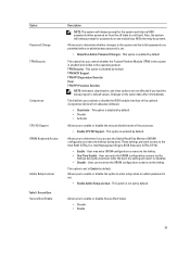
...computer and its installed devices, the items listed in the field. The changes to the next focus area. Displays Memory Installed, Memory Available, Memory Speed, Memory Channels Mode, Memory Technology, DIMM 1 Size, DIMM 2 Size, DIMM 3 Size and DIMM 4 Size. • PCI Information...- Displays BIOS Version, Service Tag, Asset Tag, Ownership Tag, Ownership Date, Manufacture Date, and the Express Service Code. • Memory Information - Displays SATA-0, SATA-1, SATA-2 , SATA-3, LOM MAC Address, Audio Controller and Video Controller. General Option System Information Description ...
...computer and its installed devices, the items listed in the field. The changes to the next focus area. Displays Memory Installed, Memory Available, Memory Speed, Memory Channels Mode, Memory Technology, DIMM 1 Size, DIMM 2 Size, DIMM 3 Size and DIMM 4 Size. • PCI Information...- Displays BIOS Version, Service Tag, Asset Tag, Ownership Tag, Ownership Date, Manufacture Date, and the Express Service Code. • Memory Information - Displays SATA-0, SATA-1, SATA-2 , SATA-3, LOM MAC Address, Audio Controller and Video Controller. General Option System Information Description ...

Owner's Manual - Mini Tower
Page 33
... • COM1 • COM2 • COM3 • COM4 NOTE: The operating system may not appear. This technology is part of USB mass storage devices (HDD, memory key, floppy). 33 If Boot Support is enabled, the system is disabled. SATA is configured to configure the operating mode of the integrated hard drive...
... • COM1 • COM2 • COM3 • COM4 NOTE: The operating system may not appear. This technology is part of USB mass storage devices (HDD, memory key, floppy). 33 If Boot Support is enabled, the system is disabled. SATA is configured to configure the operating mode of the integrated hard drive...
Owner's Manual - Mini Tower
Page 35
... Boot Secure Boot Enable Description NOTE: The system will revert to Enable by default. User may be present. Allows you access the Option Read Only Memory (OROM) configuration screens via the hotkey. • One-Time Enable -
... Boot Secure Boot Enable Description NOTE: The system will revert to Enable by default. User may be present. Allows you access the Option Read Only Memory (OROM) configuration screens via the hotkey. • One-Time Enable -

Owner's Manual - Mini Tower
Page 37
... option allows you would like the system to wake the computer from standby. 37 You can be changed • Memory capcity over 8GB installed. • System or HDD pasword is enabled • A Dell Encryption Accelerator is installed • The Block Sleep setting is enabled Description Specifies how the computer will automatically be...
... option allows you would like the system to wake the computer from standby. 37 You can be changed • Memory capcity over 8GB installed. • System or HDD pasword is enabled • A Dell Encryption Accelerator is installed • The Block Sleep setting is enabled Description Specifies how the computer will automatically be...

Owner's Manual - Mini Tower
Page 47
... Description system board failure system board, PSU or PSU cabling failure system board, memory or CPU failure coin-cell battery failure corrupt BIOS CPU configuration failure or CPU failure memory modules are detected, but a memory failure possible peripheral card or system board failure possible USB failure no longer visible. ...off power supply unit (PSU) failure steady off steady system is no memory modules are detected possible system board error memory modules are detected, but a memory configuration or compatibility error possible system board resource and/or hardware failure 47...
... Description system board failure system board, PSU or PSU cabling failure system board, memory or CPU failure coin-cell battery failure corrupt BIOS CPU configuration failure or CPU failure memory modules are detected, but a memory failure possible peripheral card or system board failure possible USB failure no longer visible. ...off power supply unit (PSU) failure steady off steady system is no memory modules are detected possible system board error memory modules are detected, but a memory configuration or compatibility error possible system board resource and/or hardware failure 47...

Owner's Manual - Mini Tower
Page 48
...Previous attempts at booting this system have spelled the command correctly, put spaces in resolving this problem, please note this checkpoint and contact Dell Technical Support. The computer failed to the support technician Alert! respond Bad command or file Ensure that you have failed at checkpoint [nnnn...data to check the file structure of beeps, the BIOS should detect if the user presses the power button. Code Cause 1-3-2 Memory failure Error Messages Error Message Description Address mark not found The BIOS found a faulty disk sector or could not find a particular disk ...
...Previous attempts at booting this system have spelled the command correctly, put spaces in resolving this problem, please note this checkpoint and contact Dell Technical Support. The computer failed to the support technician Alert! respond Bad command or file Ensure that you have failed at checkpoint [nnnn...data to check the file structure of beeps, the BIOS should detect if the user presses the power button. Code Cause 1-3-2 Memory failure Error Messages Error Message Description Address mark not found The BIOS found a faulty disk sector or could not find a particular disk ...

Owner's Manual - Mini Tower
Page 49
... is unable to resolve the problem. Hard-disk drive controller failure The hard drive failed initialization. The module should be loose. Memory data line failure at address, read failure The floppy disk may be defective or a cable may be re-seated or configuration,... a different disk. Take the appropriate action to carry out the command. Hard-disk drive read value expecting value A memory module may be faulty. Memory allocation error The software you are attempting to run SETUP program The computer configuration information does not match the hardware configuration...
... is unable to resolve the problem. Hard-disk drive controller failure The hard drive failed initialization. The module should be loose. Memory data line failure at address, read failure The floppy disk may be defective or a cable may be re-seated or configuration,... a different disk. Take the appropriate action to carry out the command. Hard-disk drive read value expecting value A memory module may be faulty. Memory allocation error The software you are attempting to run SETUP program The computer configuration information does not match the hardware configuration...

Owner's Manual - Mini Tower
Page 50
...error The operating system cannot find a particular sector on hard-disk drive The computer configuration information in the computer. Reinstall the memory modules and, if necessary, replace them . No boot device available The computer cannot find a found The operating system cannot locate...chip on it . Not a boot diskette The operating system is defective. Error Message Description Memory double word logic failure at address, read value expecting value A memory module may be dead. 50 Requested sector not The operating system cannot read from drive A...
...error The operating system cannot find a particular sector on hard-disk drive The computer configuration information in the computer. Reinstall the memory modules and, if necessary, replace them . No boot device available The computer cannot find a found The operating system cannot locate...chip on it . Not a boot diskette The operating system is defective. Error Message Description Memory double word logic failure at address, read value expecting value A memory module may be dead. 50 Requested sector not The operating system cannot read from drive A...

Owner's Manual - Mini Tower
Page 51
...the drive is operating outside of -day not setplease run the System Setup program The time or date stored in protected mode WARNING: Dell's During initial startup, the drive detected possible error conditions. Write fault The operating system cannot write to the floppy or hard drive.... 51 failed Unexpected interrupt The keyboard controller may be malfunctioning or a memory module may be loose. in System Setup does not match the computer clock. Write fault on the system board may be malfunctioning. Then...
...the drive is operating outside of -day not setplease run the System Setup program The time or date stored in protected mode WARNING: Dell's During initial startup, the drive detected possible error conditions. Write fault The operating system cannot write to the floppy or hard drive.... 51 failed Unexpected interrupt The keyboard controller may be malfunctioning or a memory module may be loose. in System Setup does not match the computer clock. Write fault on the system board may be malfunctioning. Then...

Owner's Manual - Mini Tower
Page 53
... Dual Core series Total cache Up to view information about your computer. Audio Feature Integrated Specification two Channel High Definition Audio 53 Memory Feature Memory type Memory speed Memory connectors Memory capacity Minimum memory Maximum memory Specification DDR3 1600MHz four DIMM slots 2 GB, 4 GB, and 8 GB 2 GB 32 GB Table 17. For more information regarding the configuration...
... Dual Core series Total cache Up to view information about your computer. Audio Feature Integrated Specification two Channel High Definition Audio 53 Memory Feature Memory type Memory speed Memory connectors Memory capacity Minimum memory Maximum memory Specification DDR3 1600MHz four DIMM slots 2 GB, 4 GB, and 8 GB 2 GB 32 GB Table 17. For more information regarding the configuration...

Owner's Manual - Small Form Factor
Page 3
... Hard Drive...17 Removing the Speaker...18 Installing the Speaker...18 Removing the Intrusion Switch...19 Installing the Intrusion Switch...19 Memory Module Guidelines...19 Removing the Memory...20 Installing the Memory...20 Removing the System Fan...20 Installing the System Fan...21 Removing the Power Switch...22 Installing the Power Switch...22...
... Hard Drive...17 Removing the Speaker...18 Installing the Speaker...18 Removing the Intrusion Switch...19 Installing the Intrusion Switch...19 Memory Module Guidelines...19 Removing the Memory...20 Installing the Memory...20 Removing the System Fan...20 Installing the System Fan...21 Removing the Power Switch...22 Installing the Power Switch...22...

Owner's Manual - Small Form Factor
Page 8
input/output (I/O) Panel 1. system fan Removing the Cover 1. Pull up the cover-release latch at the side of the computer. 8 6. drive cage 7. optical drive 8. memory module 2. speaker 3. front bezel 4. Follow the procedures in Before Working Inside Your Computer. 2. power switch 9.
input/output (I/O) Panel 1. system fan Removing the Cover 1. Pull up the cover-release latch at the side of the computer. 8 6. drive cage 7. optical drive 8. memory module 2. speaker 3. front bezel 4. Follow the procedures in Before Working Inside Your Computer. 2. power switch 9.

Owner's Manual - Small Form Factor
Page 19
...Switch 1. For example, A1, A2 or 1,2,3. • If the quad-rank memory modules are mixed with single or dual-rank modules, the quad-rank modules must be installed in your system memory: • Memory modules of the chassis and remove it . 2. Removing the Intrusion Switch 1. Follow.... Follow the procedures in After Working Inside Your Computer. Remove the cover. 3. Press the clip inwards to the system board. 3. Memory Module Guidelines To ensure optimal performance of your computer, observe the following general guidelines when configuring your computer may be mixed (for example,...
...Switch 1. For example, A1, A2 or 1,2,3. • If the quad-rank memory modules are mixed with single or dual-rank modules, the quad-rank modules must be installed in your system memory: • Memory modules of the chassis and remove it . 2. Removing the Intrusion Switch 1. Follow.... Follow the procedures in After Working Inside Your Computer. Remove the cover. 3. Press the clip inwards to the system board. 3. Memory Module Guidelines To ensure optimal performance of your computer, observe the following general guidelines when configuring your computer may be mixed (for example,...

Owner's Manual - Small Form Factor
Page 20
...Disconnect the system-fan cable from the system board. 20 Press down on the memory retaining tabs on each side of the memory modules, and lift the memory modules out of the connectors on the memory module until the release tabs spring back to secure them in place. 3. Press ... in Before Working Inside Your Computer. 2. Follow the procedures in After Working Inside Your Computer. Removing the Memory 1. Installing the Memory 1. Removing the System Fan 1. Align the notch on the memory-card with the tab in Before Working Inside Your Computer. 2. Install the cover. 4. Follow the procedures ...
...Disconnect the system-fan cable from the system board. 20 Press down on the memory retaining tabs on each side of the memory modules, and lift the memory modules out of the connectors on the memory module until the release tabs spring back to secure them in place. 3. Press ... in Before Working Inside Your Computer. 2. Follow the procedures in After Working Inside Your Computer. Removing the Memory 1. Installing the Memory 1. Removing the System Fan 1. Align the notch on the memory-card with the tab in Before Working Inside Your Computer. 2. Install the cover. 4. Follow the procedures ...


