

Service Manual
Page 2
... in any proprietary interest in trademarks and trade names other than its own. Other trademarks and trade names may be used in this text: Dell, the DELL logo, and OptiPlex are registered trademarks of International Business Machines Corporation; 3Com is strictly forbidden. Information in this document to refer to change without the written...
... in any proprietary interest in trademarks and trade names other than its own. Other trademarks and trade names may be used in this text: Dell, the DELL logo, and OptiPlex are registered trademarks of International Business Machines Corporation; 3Com is strictly forbidden. Information in this document to refer to change without the written...
Service Manual
Page 3
Contents Chapter 1 System Overview 1-1 System Features 1-2 Dual-Processor Capability 1-5 Advanced Expansion Subsystem 1-5 Hard-Disk Drive Options 1-6 Enhanced Dual-Interface EIDE Subsystem 1-6 Audio Controller 1-6 PCI Video Card 1-6 NIC 1-7 USB 1-7 Desktop Chassis 1-7 Thermal Monitoring 1-7 System Unit 1-8 System Power Supply 1-8 Pin Assignments for the DC Power Connectors 1-8 DC Power Distribution 1-10 System Board Layout 1-12 Video Memory 1-12 Main Memory 1-13 System Board Jumpers 1-13 Interrupt Assignments 1-14 DMA Channel Assignments 1-15 Technical Specifications 1-...
Contents Chapter 1 System Overview 1-1 System Features 1-2 Dual-Processor Capability 1-5 Advanced Expansion Subsystem 1-5 Hard-Disk Drive Options 1-6 Enhanced Dual-Interface EIDE Subsystem 1-6 Audio Controller 1-6 PCI Video Card 1-6 NIC 1-7 USB 1-7 Desktop Chassis 1-7 Thermal Monitoring 1-7 System Unit 1-8 System Power Supply 1-8 Pin Assignments for the DC Power Connectors 1-8 DC Power Distribution 1-10 System Board Layout 1-12 Video Memory 1-12 Main Memory 1-13 System Board Jumpers 1-13 Interrupt Assignments 1-14 DMA Channel Assignments 1-15 Technical Specifications 1-...
Service Manual
Page 4
Chapter 2 Basic Troubleshooting 2-1 Initial User Contact 2-1 External Visual Inspection 2-2 Observing the Boot Routine 2-3 Internal Visual Inspection 2-4 Eliminating Resource Conflicts 2-5 Running the Diskette-Based Diagnostics 2-5 Getting Help 2-6 Chapter 3 Beep Codes and Error Messages 3-1 POST Beep Codes 3-1 System Error Messages 3-3 Chapter 4 Removing and Replacing Parts 4-1 Recommended Tools 4-1 Precautionary Measures 4-2 Floor Stand 4-3 System Unit Cover 4-4 Eject, Power, and Reset Buttons 4-5 Front-Panel Inserts 4-6 Indicator Card 4-7 Speaker 4-8 Drives 4-9 Drives ...
Chapter 2 Basic Troubleshooting 2-1 Initial User Contact 2-1 External Visual Inspection 2-2 Observing the Boot Routine 2-3 Internal Visual Inspection 2-4 Eliminating Resource Conflicts 2-5 Running the Diskette-Based Diagnostics 2-5 Getting Help 2-6 Chapter 3 Beep Codes and Error Messages 3-1 POST Beep Codes 3-1 System Error Messages 3-3 Chapter 4 Removing and Replacing Parts 4-1 Recommended Tools 4-1 Precautionary Measures 4-2 Floor Stand 4-3 System Unit Cover 4-4 Eject, Power, and Reset Buttons 4-5 Front-Panel Inserts 4-6 Indicator Card 4-7 Speaker 4-8 Drives 4-9 Drives ...
Service Manual
Page 5
DC Power Connector P1 1-9 Figure 1-6. DC Power Cables 1-10 Figure 1-9. Padlock Removal 4-4 Figure 4-4. Terminator Card 4-23 Add-In Card 4-24 System Battery 4-25 System Board 4-26 Appendix A System Setup Program A-1 System Setup Screens A-2 Index Figures Figure 1-1. Internal View 1-4 Figure 1-4. DC Power Connectors P2, P3, P4, P5, and P6 1-9 Figure 1-7. System Board Components 1-12 Figure 1-11. Hard-Disk Drive Removal 4-13 Figure 4-13. Power Distribution 1-11 Figure 1-10. Microprocessor Fan Removal 4-15 Figure 4-15. System Unit Orientation 1-3 Figure ...
DC Power Connector P1 1-9 Figure 1-6. DC Power Cables 1-10 Figure 1-9. Padlock Removal 4-4 Figure 4-4. Terminator Card 4-23 Add-In Card 4-24 System Battery 4-25 System Board 4-26 Appendix A System Setup Program A-1 System Setup Screens A-2 Index Figures Figure 1-1. Internal View 1-4 Figure 1-4. DC Power Connectors P2, P3, P4, P5, and P6 1-9 Figure 1-7. System Board Components 1-12 Figure 1-11. Hard-Disk Drive Removal 4-13 Figure 4-13. Power Distribution 1-11 Figure 1-10. Microprocessor Fan Removal 4-15 Figure 4-15. System Unit Orientation 1-3 Figure ...
Service Manual
Page 8
.... Warnings, Cautions, and Notes Throughout this manual, there may be blocks of text printed in bold type or in this manual to service Dell computer systems is a basic knowledge of data and provides instructions for how to avoid the problem. CAUTION: A CAUTION indicates either potential damage... IBM®-compatible PCs and prior training in IBMcompatible PC troubleshooting techniques. NOTE: A NOTE provides helpful information about using the Dell diagnostics to test the computer system. Read This First A prerequisite for using this manual and the User's Guide that came with the ...
.... Warnings, Cautions, and Notes Throughout this manual, there may be blocks of text printed in bold type or in this manual to service Dell computer systems is a basic knowledge of data and provides instructions for how to avoid the problem. CAUTION: A CAUTION indicates either potential damage... IBM®-compatible PCs and prior training in IBMcompatible PC troubleshooting techniques. NOTE: A NOTE provides helpful information about using the Dell diagnostics to test the computer system. Read This First A prerequisite for using this manual and the User's Guide that came with the ...
Service Manual
Page 9
... incorporate the high-performance PCI local bus as well as follows: • Dell OptiPlex GXpro 180 systems - 180 MHz derived from a system clock frequency of 60 MHz • Dell OptiPlex GXpro 200 systems - 200 MHz derived from a system clock frequency of 66 MHz Dell OptiPlex GXpro systems contain either an integrated 10-Mbps or 10/100-Mbps 3Com®... are as the ISA expansion bus. The Pentium Pro microprocessor contains a built-in this document. System Overview 1-1 Chapter 1 System Overview This service manual covers the Dell® OptiPlex® GXpro high-speed, upgrad-
... incorporate the high-performance PCI local bus as well as follows: • Dell OptiPlex GXpro 180 systems - 180 MHz derived from a system clock frequency of 60 MHz • Dell OptiPlex GXpro 200 systems - 200 MHz derived from a system clock frequency of 66 MHz Dell OptiPlex GXpro systems contain either an integrated 10-Mbps or 10/100-Mbps 3Com®... are as the ISA expansion bus. The Pentium Pro microprocessor contains a built-in this document. System Overview 1-1 Chapter 1 System Overview This service manual covers the Dell® OptiPlex® GXpro high-speed, upgrad-
Service Manual
Page 10
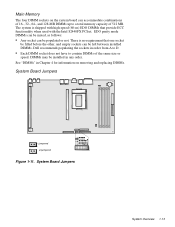
... DIMMs that the location or direction relative to the system unit is as shown in Figure 1-1. 1-2 Dell OptiPlex GXpro Systems Service Manual For a complete list of system features, see "Technical Specifications" found in a traditional personal computer, the Dell OptiPlex GXpro desktop systems include the following the text in this manual, assume that provide ECC functionality when...
... DIMMs that the location or direction relative to the system unit is as shown in Figure 1-1. 1-2 Dell OptiPlex GXpro Systems Service Manual For a complete list of system features, see "Technical Specifications" found in a traditional personal computer, the Dell OptiPlex GXpro desktop systems include the following the text in this manual, assume that provide ECC functionality when...
Service Manual
Page 11
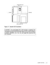
System Unit Orientation CAUTION: To avoid possible data or file structure corruptions, the front-panel reset button should be used only when the system cannot be rebooted by pressing . Before you use the reset button to initiate a hardware reset, close any open application programs and files if possible. back of system unit left side right side front of system unit Figure 1-1. System Overview 1-3
System Unit Orientation CAUTION: To avoid possible data or file structure corruptions, the front-panel reset button should be used only when the system cannot be rebooted by pressing . Before you use the reset button to initiate a hardware reset, close any open application programs and files if possible. back of system unit left side right side front of system unit Figure 1-1. System Overview 1-3
Service Manual
Page 12
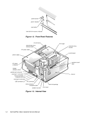
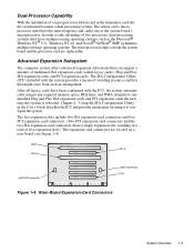
power button power indicator reset button hard-disk drive access indicator Figure 1-2. Internal View expansion-card cage chassis 1-4 Dell OptiPlex GXpro Systems Service Manual Front-Panel Features 3.5-inch drive diskette/tape drive interface cable DC power cable power supply drive cage hard-disk drive bracket system ...
power button power indicator reset button hard-disk drive access indicator Figure 1-2. Internal View expansion-card cage chassis 1-4 Dell OptiPlex GXpro Systems Service Manual Front-Panel Features 3.5-inch drive diskette/tape drive interface cable DC power cable power supply drive cage hard-disk drive bracket system ...
Service Manual
Page 13
Advanced Expansion Subsystem The computer system offers advanced expansion subsystems that might arise from such an arrangement. After all legacy cards have multiprocessing operating systems, such as the system board's microprocessor. Chapter 4, "Using the ISA Configuration Utility," in a total of five expansion slots.) The expansion-card connectors are located on both the system board and the processor card are replaceable. The five expansion slots include two ISA expansion-card connectors and five PCI expansion-card connectors. (Two PCI expansion-card connectors and the two ISA ...
Advanced Expansion Subsystem The computer system offers advanced expansion subsystems that might arise from such an arrangement. After all legacy cards have multiprocessing operating systems, such as the system board's microprocessor. Chapter 4, "Using the ISA Configuration Utility," in a total of five expansion slots.) The expansion-card connectors are located on both the system board and the processor card are replaceable. The five expansion slots include two ISA expansion-card connectors and five PCI expansion-card connectors. (Two PCI expansion-card connectors and the two ISA ...
Service Manual
Page 14
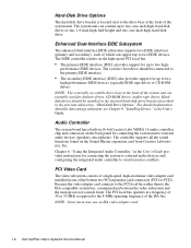
... the internal hard-disk drive bracket described in the previous subsection, "Hard-Disk Drive Options." NOTE: Some users may use an ISA video adapter card. 1-6 Dell OptiPlex GXpro Systems Service Manual The system unit can support up to the ISA-compatible system bus, communication between the video subsystem and the microprocessor is located...
... the internal hard-disk drive bracket described in the previous subsection, "Hard-Disk Drive Options." NOTE: Some users may use an ISA video adapter card. 1-6 Dell OptiPlex GXpro Systems Service Manual The system unit can support up to the ISA-compatible system bus, communication between the video subsystem and the microprocessor is located...
Service Manual
Page 15
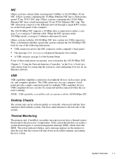
... devices such as mice, printers, and computer speakers. USB-compliant devices can be connected and disconnected while the system is running. GXpro systems containing the 10/100-Mbps Ethernet NIC have a thermal sensor that the system will shut down in an orderly manner, preventing... the loss of data. GXpro systems with the system. Chapter 5, "Using the Network Interface Controller," in integrated 3Com 3C916 Ethernet NIC chip. NOTE: USB capability is exceeded...
... devices such as mice, printers, and computer speakers. USB-compliant devices can be connected and disconnected while the system is running. GXpro systems containing the 10/100-Mbps Ethernet NIC have a thermal sensor that the system will shut down in an orderly manner, preventing... the loss of data. GXpro systems with the system. Chapter 5, "Using the Network Interface Controller," in integrated 3Com 3C916 Ethernet NIC chip. NOTE: USB capability is exceeded...
Service Manual
Page 16
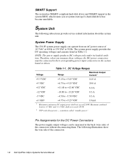
... 1-1. Maximum combined load on the system board or drives. . sometimes called "standby power." . System Unit The following illustrations show the wire side of the connectors. 1-8 Dell OptiPlex GXpro Systems Service Manual System Power Supply The 230-W system power supply can be connected to +5.25 VDC 10 mA 1 Maximum continuous DC output power shall...
... 1-1. Maximum combined load on the system board or drives. . sometimes called "standby power." . System Unit The following illustrations show the wire side of the connectors. 1-8 Dell OptiPlex GXpro Systems Service Manual System Power Supply The 230-W system power supply can be connected to +5.25 VDC 10 mA 1 Maximum continuous DC output power shall...
Service Manual
Page 17
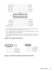
PSON# should measure between +4 and +5 VDC except when the power button on and operating to indicate that all power-supply output voltages are within ranges specified in special applications. 3 Pin 5 - Figure 1-5. DC Power Connectors P2, P3, P4, P5, and P6 System Overview 1-9 DC Power Connector P1 1234 P2, P3, P5, P6 +5 VDC (red) common (black) common (black) +12 VDC (yellow) P4 12 34 +12 VDC (yellow) common (black) common (black) +5 VDC (red) Figure 1-6. Thermal fan-speed control (TFSC) is pressed, taking PSON# to control power-supply fan speed in Table 1-1. -5 VDC (...
PSON# should measure between +4 and +5 VDC except when the power button on and operating to indicate that all power-supply output voltages are within ranges specified in special applications. 3 Pin 5 - Figure 1-5. DC Power Connectors P2, P3, P4, P5, and P6 System Overview 1-9 DC Power Connector P1 1234 P2, P3, P5, P6 +5 VDC (red) common (black) common (black) +12 VDC (yellow) P4 12 34 +12 VDC (yellow) common (black) common (black) +5 VDC (red) Figure 1-6. Thermal fan-speed control (TFSC) is pressed, taking PSON# to control power-supply fan speed in Table 1-1. -5 VDC (...
Service Manual
Page 18
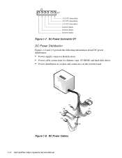
P7 1 2 34 5 6 +3.3 VDC (blue/white) +3.3 VDC (blue/white) +3.3 VDC (blue/white) common (black) common (black) common (black) Figure 1-7. DC Power Connector P7 DC Power Distribution Figures 1-8 and 1-9 provide the following information about DC power distribution: • Power-supply connector identification • Power cable connections for diskette, tape, CD-ROM, and hard-disk drives • Power distribution to sockets and connectors on the system board P4 P6 P5 P3 P1 P7 P2 Figure 1-8. DC Power Cables 1-10 Dell OptiPlex GXpro Systems Service Manual
P7 1 2 34 5 6 +3.3 VDC (blue/white) +3.3 VDC (blue/white) +3.3 VDC (blue/white) common (black) common (black) common (black) Figure 1-7. DC Power Connector P7 DC Power Distribution Figures 1-8 and 1-9 provide the following information about DC power distribution: • Power-supply connector identification • Power cable connections for diskette, tape, CD-ROM, and hard-disk drives • Power distribution to sockets and connectors on the system board P4 P6 P5 P3 P1 P7 P2 Figure 1-8. DC Power Cables 1-10 Dell OptiPlex GXpro Systems Service Manual
Service Manual
Page 19
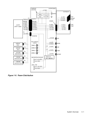
keyboard controller system board +3 VDC system power supply P1 PWRGOOD PSON# +5 VFP +5 VDC -5 VDC +12 VDC -12 VDC POWER1 power management logic PSON# +5 VFP +5 VDC -5 VDC +12 VDC -12 VDC RTC/ NVRAM battery RISER +5 VDC -5 VDC +12 VDC -12 VDC riser board +5 VDC +12 VDC -12 VDC +5 VDC -5 VDC +12 VDC -12 VDC PCI1 through PCI5 ISA1, ISA2 P7 +3.3 VDC POWER2 +12 VDC FAN optional P2 drive optional P3 drive P4 3.5-inch diskette drive P5 internal hard-disk drive P6 internal hard-disk drive main memory sockets DIMM_A DIMM_B DIMM_C DIMM_D MICROPROCESSOR +2.1-3.5 VDC +3.3 VDC +5 ...
keyboard controller system board +3 VDC system power supply P1 PWRGOOD PSON# +5 VFP +5 VDC -5 VDC +12 VDC -12 VDC POWER1 power management logic PSON# +5 VFP +5 VDC -5 VDC +12 VDC -12 VDC RTC/ NVRAM battery RISER +5 VDC -5 VDC +12 VDC -12 VDC riser board +5 VDC +12 VDC -12 VDC +5 VDC -5 VDC +12 VDC -12 VDC PCI1 through PCI5 ISA1, ISA2 P7 +3.3 VDC POWER2 +12 VDC FAN optional P2 drive optional P3 drive P4 3.5-inch diskette drive P5 internal hard-disk drive P6 internal hard-disk drive main memory sockets DIMM_A DIMM_B DIMM_C DIMM_D MICROPROCESSOR +2.1-3.5 VDC +3.3 VDC +5 ...
Service Manual
Page 20
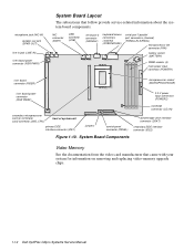
... power connector (RSR PWR1) System Board Layout The subsections that came with your system for information on removing and replacing video-memory upgrade chips. 1-12 Dell OptiPlex GXpro Systems Service Manual
... power connector (RSR PWR1) System Board Layout The subsections that came with your system for information on removing and replacing video-memory upgrade chips. 1-12 Dell OptiPlex GXpro Systems Service Manual
Service Manual
Page 21
... the other, and empty sockets can be populated or not. There is shipped with the Intel 82440FX PCIset. DIMMs may be left between installed DIMMs. Dell recommends populating the sockets in order from A to D. • Each DIMM socket does not have to a total memory capacity of the same size or speed...
... the other, and empty sockets can be populated or not. There is shipped with the Intel 82440FX PCIset. DIMMs may be left between installed DIMMs. Dell recommends populating the sockets in order from A to D. • Each DIMM socket does not have to a total memory capacity of the same size or speed...
Service Manual
Page 22
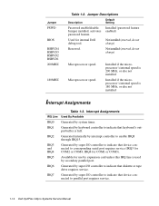
... RSRVD1 200MHZ 180MHZ Table 1-2. Used for use by expansion card unless this IRQ line is used by interrupt controller to parallel port requires service. 1-14 Dell OptiPlex GXpro Systems Service Manual Installed if the microprocessor's internal speed is 200 MHz, or else not installed Installed if the microprocessor's internal speed is full. IRQ3...
... RSRVD1 200MHZ 180MHZ Table 1-2. Used for use by expansion card unless this IRQ line is used by interrupt controller to parallel port requires service. 1-14 Dell OptiPlex GXpro Systems Service Manual Installed if the microprocessor's internal speed is 200 MHz, or else not installed Installed if the microprocessor's internal speed is full. IRQ3...
Service Manual
Page 23
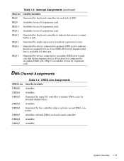
If no EIDE devices are installed, this line is full. Interrupt Assignments (continued) IRQ Line Used By/Available IRQ8 Generated by keyboard controller for use by expansion card. IRQ11 Available for use by expansion card. IRQ14 Generated by bus controller chip to indicate that mouse's output buffer is available for use . IRQ9 Available for use by expansion card. IRQ10 Available for other use by keyboard controller to activate second DMA controller DREQ5 Available (default) DMA on-board sound controller DREQ6 Available DREQ7 Available System Overview 1-...
If no EIDE devices are installed, this line is full. Interrupt Assignments (continued) IRQ Line Used By/Available IRQ8 Generated by keyboard controller for use by expansion card. IRQ11 Available for use by expansion card. IRQ14 Generated by bus controller chip to indicate that mouse's output buffer is available for use . IRQ9 Available for use by expansion card. IRQ10 Available for other use by keyboard controller to activate second DMA controller DREQ5 Available (default) DMA on-board sound controller DREQ6 Available DREQ7 Available System Overview 1-...