User Guide
Page 7
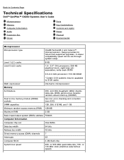
Back to microprocessor Memory Architecture 200- Math coprocessor internal to Contents Page Technical Specifications Dell™ OptiPlex™ GX260 Systems User's Guide Microprocessor Memory Computer Information Audio Expansion Bus Drives Ports Key Combinations Controls and Lights Power Physical Environmental Microprocessor Microprocessor type ... Computer BIOS 4-Mb flash chip System bus speed 400- Design provides for future Dell-supported upgrades. or 133-MHz clock (matches external bus speed) A slower compatibility speed can be upgraded to 512K...
Back to microprocessor Memory Architecture 200- Math coprocessor internal to Contents Page Technical Specifications Dell™ OptiPlex™ GX260 Systems User's Guide Microprocessor Memory Computer Information Audio Expansion Bus Drives Ports Key Combinations Controls and Lights Power Physical Environmental Microprocessor Microprocessor type ... Computer BIOS 4-Mb flash chip System bus speed 400- Design provides for future Dell-supported upgrades. or 133-MHz clock (matches external bus speed) A slower compatibility speed can be upgraded to 512K...

User Guide
Page 8
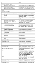
... bay for a 5.25-inch CD/DVD drive two bays for two 3.5-inch floppy drives two bays for two 5.25-inch CD/DVD Audio Audio type AC97, Sound Blaster emulation Audio controller Integrated AC97 Codec Stereo conversion Interfaces: Internal External Expansion Bus Bus types Bus speed 16-bit analog-to 22.9 cm [9 inches] long...
... bay for a 5.25-inch CD/DVD drive two bays for two 3.5-inch floppy drives two bays for two 5.25-inch CD/DVD Audio Audio type AC97, Sound Blaster emulation Audio controller Integrated AC97 Codec Stereo conversion Interfaces: Internal External Expansion Bus Bus types Bus speed 16-bit analog-to 22.9 cm [9 inches] long...
User Guide
Page 9
... System/2 (PS/2)-style keyboard PS/2-compatible mouse Universal Serial Bus (USB) Internally accessible: Primary IDE hard drive Secondary IDE hard drive Floppy drive CD drive audio interface Telephony Fan PCI Key Combinations or drives one bay for a 1-inch-high IDE hard drive one bay for a 1-inch-high IDE hard drive two...
... System/2 (PS/2)-style keyboard PS/2-compatible mouse Universal Serial Bus (USB) Internally accessible: Primary IDE hard drive Secondary IDE hard drive Floppy drive CD drive audio interface Telephony Fan PCI Key Combinations or drives one bay for a 1-inch-high IDE hard drive one bay for a 1-inch-high IDE hard drive two...
User Guide
Page 12
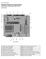
... System Board Components Dell™ OptiPlex™ GX260 Systems User's Guide System Board 1 floppy drive connector (DSKT) 2 internal speaker (SPEAKER) 3 battery socket (BATTERY) 4 CD/DVD drive connector (IDE2) 5 hard drive connector (IDE1) 6 front-panel connector (FRONTPANEL) 7 PCI riser (small mini-tower computer only) 8 standby power light (AUX_PWR) 12 CD drive audio cable connector...
... System Board Components Dell™ OptiPlex™ GX260 Systems User's Guide System Board 1 floppy drive connector (DSKT) 2 internal speaker (SPEAKER) 3 battery socket (BATTERY) 4 CD/DVD drive connector (IDE2) 5 hard drive connector (IDE1) 6 front-panel connector (FRONTPANEL) 7 PCI riser (small mini-tower computer only) 8 standby power light (AUX_PWR) 12 CD drive audio cable connector...
User Guide
Page 49
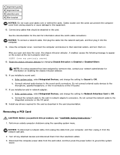
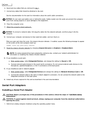
...the network wall jack, and then plug it from their electrical outlets, and turn them from the network wall jack. 2. b. Connect external audio devices to Enabled or Enabled-Silent. Removing a PCI Card CAUTION: Before you installed a sound card: a. Do not connect the network cable...you installed an add-in network adapter's connectors. If you perform this procedure, see "CAUTION: Safety Instructions." 1. Do not connect external audio devices to appear on the screen at the next computer start-up: ALERT! Enter system setup, select Integrated Devices, and change the ...
...the network wall jack, and then plug it from their electrical outlets, and turn them from the network wall jack. 2. b. Connect external audio devices to Enabled or Enabled-Silent. Removing a PCI Card CAUTION: Before you installed a sound card: a. Do not connect the network cable...you installed an add-in network adapter's connectors. If you perform this procedure, see "CAUTION: Safety Instructions." 1. Do not connect external audio devices to appear on the screen at the next computer start-up: ALERT! Enter system setup, select Integrated Devices, and change the ...
User Guide
Page 65
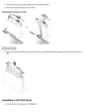
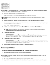
Removing the Interposer Board 1 interposer board 3. Unpack the drive and prepare it from the drive. Press inward on the two tabs on the sides of the drive, and then slide the drive upward and remove it for installation. Remove the interposer board from the drive bay. Installing a CD/DVD Drive 1. 1. Disconnect the power and audio cables from the interposer board. 2.
Removing the Interposer Board 1 interposer board 3. Unpack the drive and prepare it from the drive. Press inward on the two tabs on the sides of the drive, and then slide the drive upward and remove it for installation. Remove the interposer board from the drive bay. Installing a CD/DVD Drive 1. 1. Disconnect the power and audio cables from the interposer board. 2.

User Guide
Page 66
Connect the interposer board to the interposer board. Ensure that the drive is configured for the cable select setting. 2. Attach the power and audio cables to the CD drive: a. If you are installing an IDE drive, configure the drive for your computer. Gently slide the drive into place until ...
Connect the interposer board to the interposer board. Ensure that the drive is configured for the cable select setting. 2. Attach the power and audio cables to the CD drive: a. If you are installing an IDE drive, configure the drive for your computer. Gently slide the drive into place until ...

User Guide
Page 74
... electrical outlet before opening the cover. Connect the other end of the procedures in this configuration to record and play audio files over the telephone by using third-party software. If enabled, the chassis intrusion detector causes the following message to... labeled MODEM or TELEPHONY). If your audio speakers and microphone as an answering machine or speakerphone. Installing a TAPI-Compliant Modem Card 1. Open the computer cover. 6. Back to Contents Page Telephony Applications Programming Interface (TAPI) Dell™ OptiPlex™ GX260 Systems User's Guide NOTE...
... electrical outlet before opening the cover. Connect the other end of the procedures in this configuration to record and play audio files over the telephone by using third-party software. If enabled, the chassis intrusion detector causes the following message to... labeled MODEM or TELEPHONY). If your audio speakers and microphone as an answering machine or speakerphone. Installing a TAPI-Compliant Modem Card 1. Open the computer cover. 6. Back to Contents Page Telephony Applications Programming Interface (TAPI) Dell™ OptiPlex™ GX260 Systems User's Guide NOTE...

User Guide
Page 75
...by someone else, contact your modem to a TAPI-compliant sound card connector (typically labeled TAD) and then use the audio capabilities as a speakerphone. 1. Connect external audio devices to Enabled or Enabled-Silent. NOTE: If a setup password has been assigned by changing Chassis Intrusion to the... resetting the chassis intrusion detector. 13. Turn off any attached devices and disconnect them on the modem card. Do not connect external audio devices to Contents Page To locate the TAPI connector on the card, see the manufacturer's documentation and your computer. 8. Close the ...
...by someone else, contact your modem to a TAPI-compliant sound card connector (typically labeled TAD) and then use the audio capabilities as a speakerphone. 1. Connect external audio devices to Enabled or Enabled-Silent. NOTE: If a setup password has been assigned by changing Chassis Intrusion to the... resetting the chassis intrusion detector. 13. Turn off any attached devices and disconnect them on the modem card. Do not connect external audio devices to Contents Page To locate the TAPI connector on the card, see the manufacturer's documentation and your computer. 8. Close the ...

User Guide
Page 101
...drive. 2. Ground yourself by touching an unpainted metal surface on the computer chassis to ground the system board. 6. Disconnect the power, audio, and CD/DVD drive cables from the back of the computer, before opening the cover. 1. Turn off your computer, and then ...electricity that might harm internal components. Open the computer cover. Perform an orderly computer shutdown using the operating system menu. 2. Removing Power, Audio, and Drive Cables CAUTION: To guard against electrical shock, always unplug your computer and devices from their power sources. Removing a CD/DVD...
...drive. 2. Ground yourself by touching an unpainted metal surface on the computer chassis to ground the system board. 6. Disconnect the power, audio, and CD/DVD drive cables from the back of the computer, before opening the cover. 1. Turn off your computer, and then ...electricity that might harm internal components. Open the computer cover. Perform an orderly computer shutdown using the operating system menu. 2. Removing Power, Audio, and Drive Cables CAUTION: To guard against electrical shock, always unplug your computer and devices from their power sources. Removing a CD/DVD...

User Guide
Page 102
Press inward on the two tabs on the sides of the drive, and then slide the drive upward and remove it from the drive bay. 1 power cable 2 audio cable 3 CD/DVD drive cable 4 IDE2 connector 3.
Press inward on the two tabs on the sides of the drive, and then slide the drive upward and remove it from the drive bay. 1 power cable 2 audio cable 3 CD/DVD drive cable 4 IDE2 connector 3.

User Guide
Page 103
CD/DVD Drive Bracket Rails 1 drive 2 bracket rails (2) 3 screws (4) 3. If you are installing an IDE drive, configure the drive for installation. Connect the power, audio, and CD/DVD drive cables to the IDE2 system board connector. If the replacement drive does not have the bracket rails attached, remove the rails ... click into position. 4. Connect the other end of the CD/DVD drive cable to the drive. 5. Check the documentation that secure each rail). Connecting Power, Audio, and Drive Cables
CD/DVD Drive Bracket Rails 1 drive 2 bracket rails (2) 3 screws (4) 3. If you are installing an IDE drive, configure the drive for installation. Connect the power, audio, and CD/DVD drive cables to the IDE2 system board connector. If the replacement drive does not have the bracket rails attached, remove the rails ... click into position. 4. Connect the other end of the CD/DVD drive cable to the drive. 5. Check the documentation that secure each rail). Connecting Power, Audio, and Drive Cables

User Guide
Page 104
..., if enabled, causes the following message to Enabled or Enabled-Silent. Cover was previously empty, remove the front- Attach the computer stand (optional). 1 power cable 2 audio cable 3 CD/DVD drive cable 4 IDE2 connector 6.
..., if enabled, causes the following message to Enabled or Enabled-Silent. Cover was previously empty, remove the front- Attach the computer stand (optional). 1 power cable 2 audio cable 3 CD/DVD drive cable 4 IDE2 connector 6.
User Guide
Page 115
... computer stand (optional). Cover was previously removed. 11. If you installed an add-in network adapter's connectors. Do not connect external audio devices to the equipment. 8. Perform an orderly computer shutdown using the operating system menu. Connect your computer and devices to the sound ... connectors. NOTE: If a setup password has been assigned by changing Chassis Intrusion to the add-in network adapter: a. Connect external audio devices to their electrical outlets, and turn them on. Enter system setup, select Integrated Devices and change the setting for Sound to ...
... computer stand (optional). Cover was previously removed. 11. If you installed an add-in network adapter's connectors. Do not connect external audio devices to the equipment. 8. Perform an orderly computer shutdown using the operating system menu. Connect your computer and devices to the sound ... connectors. NOTE: If a setup password has been assigned by changing Chassis Intrusion to the add-in network adapter: a. Connect external audio devices to their electrical outlets, and turn them on. Enter system setup, select Integrated Devices and change the setting for Sound to ...

User Guide
Page 145
... the cable from your computer, and then unplug it from the computer. 5. Also, disconnect any static electricity that might harm internal components. Disconnect the power, audio, and CD/DVD drive cables from the electrical outlet before touching anything inside your computer and any of the procedures in this section, follow the.... 6. While you begin any devices. 3. Disconnect your computer from the back of the drive. Disconnect the computer power cable from their power sources. Removing Power, Audio, and Drive Cables
... the cable from your computer, and then unplug it from the computer. 5. Also, disconnect any static electricity that might harm internal components. Disconnect the power, audio, and CD/DVD drive cables from the electrical outlet before touching anything inside your computer and any of the procedures in this section, follow the.... 6. While you begin any devices. 3. Disconnect your computer from the back of the drive. Disconnect the computer power cable from their power sources. Removing Power, Audio, and Drive Cables

User Guide
Page 146
1 power cable 2 audio cable 3 CD/DVD drive cable 2. Press inward on the two tabs on the sides of the drive, and then slide the drive upward and remove it from the drive bay. Installing a CD/DVD Drive
1 power cable 2 audio cable 3 CD/DVD drive cable 2. Press inward on the two tabs on the sides of the drive, and then slide the drive upward and remove it from the drive bay. Installing a CD/DVD Drive

User Guide
Page 147
...installing a new drive, unpack the drive and prepare it for installation. CD/DVD Drive Bracket Rails 1 drive 2 bracket rails (2) 3 screws (4) 4. Connecting Power, Audio, and Drive Cables Gently slide the drive into place until the tabs securely click into position. 5. If you are installing a replacement drive and the new...drive to the inside of rails is configured for the cable select setting. 2. Attach the bracket to the drive. Connect the power, audio, and CD/DVD drive cables to the new drive by removing the two screws that the drive is not attached inside the cover, contact...
...installing a new drive, unpack the drive and prepare it for installation. CD/DVD Drive Bracket Rails 1 drive 2 bracket rails (2) 3 screws (4) 4. Connecting Power, Audio, and Drive Cables Gently slide the drive into place until the tabs securely click into position. 5. If you are installing a replacement drive and the new...drive to the inside of rails is configured for the cable select setting. 2. Attach the bracket to the drive. Connect the power, audio, and CD/DVD drive cables to the new drive by removing the two screws that the drive is not attached inside the cover, contact...

User Guide
Page 148
... slot. 8. After you are installing a new CD/DVD drive rather than replacing a drive, remove the front-panel inserts. 7. Cover was previously removed. 12. 1 power cable 2 audio cable 3 CD/DVD drive cable 6. Close the computer cover. Update your configuration information by someone else, contact your computer and devices to their electrical outlets...
... slot. 8. After you are installing a new CD/DVD drive rather than replacing a drive, remove the front-panel inserts. 7. Cover was previously removed. 12. 1 power cable 2 audio cable 3 CD/DVD drive cable 6. Close the computer cover. Update your configuration information by someone else, contact your computer and devices to their electrical outlets...
User Guide
Page 159
...into the network wall jack, and then plug it from their electrical outlets, and turn them from the network wall jack. 2. Connect external audio devices to Enabled or Enabled-Silent. Enter system setup, select Integrated Devices, and change the setting for Sound to their electrical outlets. 3. ...Connect the network cable to the card. Turn off any drivers required for the card as described in network adapter: a. Do not connect external audio devices to the integrated connector on the screen at the next computer start-up: ALERT! NOTICE: To connect a network cable, first plug ...
...into the network wall jack, and then plug it from their electrical outlets, and turn them from the network wall jack. 2. Connect external audio devices to Enabled or Enabled-Silent. Enter system setup, select Integrated Devices, and change the setting for Sound to their electrical outlets. 3. ...Connect the network cable to the card. Turn off any drivers required for the card as described in network adapter: a. Do not connect external audio devices to the integrated connector on the screen at the next computer start-up: ALERT! NOTICE: To connect a network cable, first plug ...
User Guide
Page 179
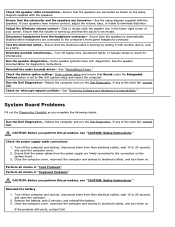
... Sound from the speakers is not muted. Reinstall the audio (sound) driver- Check the device option setting- Exit system setup and reboot the computer. Check for diagnostics instructions. Reboot the computer and run the Dell Diagnostics. Check the power supply cable connections 1. Perform ...10 to 20 seconds, and open the computer. 2. See "Resolving Software and Hardware Incompatibilities." If any of the tests fail, contact Dell. Turn off nearby fans, fluorescent lights, or halogen lamps to the computer's front-panel headphone connector. Remove the battery, wait 5...
... Sound from the speakers is not muted. Reinstall the audio (sound) driver- Check the device option setting- Exit system setup and reboot the computer. Check for diagnostics instructions. Reboot the computer and run the Dell Diagnostics. Check the power supply cable connections 1. Perform ...10 to 20 seconds, and open the computer. 2. See "Resolving Software and Hardware Incompatibilities." If any of the tests fail, contact Dell. Turn off nearby fans, fluorescent lights, or halogen lamps to the computer's front-panel headphone connector. Remove the battery, wait 5...


