Service Manual
Page 2
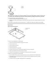
...the component to 20 seconds after disconnecting the computer from electrostatic discharge (ESD). Removing and Replacing Parts: Dell™ OptiPlex™ GX200 Systems Service Manual Overview Recommended Tools Precautionary Measures Internal Views Computer Cover Eject, Power, and Reset Buttons ...Board Overview This section provides procedures for removing and replacing the components, assemblies, and subassemblies in "Precautionary Measures." l You have performed the steps in this file require the use a wrist grounding strap as explained in the Dell OptiPlex low-profile chassis GX200...
...the component to 20 seconds after disconnecting the computer from electrostatic discharge (ESD). Removing and Replacing Parts: Dell™ OptiPlex™ GX200 Systems Service Manual Overview Recommended Tools Precautionary Measures Internal Views Computer Cover Eject, Power, and Reset Buttons ...Board Overview This section provides procedures for removing and replacing the components, assemblies, and subassemblies in "Precautionary Measures." l You have performed the steps in this file require the use a wrist grounding strap as explained in the Dell OptiPlex low-profile chassis GX200...
Service Manual
Page 3
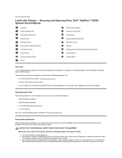
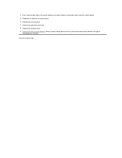
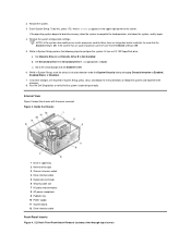
...the computer chassis, such as the padlock loop on the computer chassis to go out (see Riser Boards). Verify that might harm internal components. Low-Profile Chassis Orientation View 1 System board 2 Hard-disk drive 3 Power supply 4 Externally accessible drive bays Figure 2 shows the low-profile... from your body before touching anything inside the computer. If it to an unpainted metal surface, such as the power supply, to the system board. 4. Figure 1. Inside the Low-Profile Chassis 1 Diskette drive in upper bay 2 Diskette drive interface cable 3 Hard-disk drive interface cable ...
...the computer chassis, such as the padlock loop on the computer chassis to go out (see Riser Boards). Verify that might harm internal components. Low-Profile Chassis Orientation View 1 System board 2 Hard-disk drive 3 Power supply 4 Externally accessible drive bays Figure 2 shows the low-profile... from your body before touching anything inside the computer. If it to an unpainted metal surface, such as the power supply, to the system board. 4. Figure 1. Inside the Low-Profile Chassis 1 Diskette drive in upper bay 2 Diskette drive interface cable 3 Hard-disk drive interface cable ...
Service Manual
Page 6
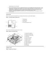
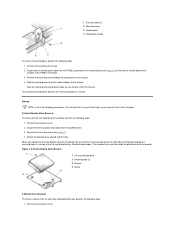
... switch out of the chassis as you reinstall the control panel, be sure to the chassis. 3. Remove the control panel from the chassis (see "System Board Labels" for the location of the control panel behind the mounting tab. Control Panel Removal 1 Control panel 2 Chassis intrusion switch To remove the control panel... chassis. Install the replacement chassis intrusion switch and cable. 4. Note the routing of the chassis intrusion cable as shown in place. 2. Hooks on the system board (see Figure 8). 3.
... switch out of the chassis as you reinstall the control panel, be sure to the chassis. 3. Remove the control panel from the chassis (see "System Board Labels" for the location of the control panel behind the mounting tab. Control Panel Removal 1 Control panel 2 Chassis intrusion switch To remove the control panel... chassis. Install the replacement chassis intrusion switch and cable. 4. Note the routing of the chassis intrusion cable as shown in place. 2. Hooks on the system board (see Figure 8). 3.
Service Manual
Page 9
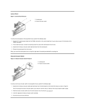
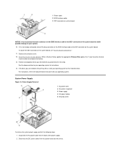
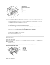
... 3 Power supply 4 DC power cables 5 Securing screw To remove the system power supply, perform the following steps: 1. To locate the IDE1 connector on the system board to avoid possible damage to your operating system. System Power Supply Figure 13. 1 Power cable 2 EIDE interface cable 3 IDE1 connector on system...: You must attach the blue connector on the EIDE interface cable to the IDE1 connector on the system board, see the online System User's Guide for instructions. 14. Reset the chassis intrusion detector. If the drive you proceed to the next step. Disconnect the ...
... 3 Power supply 4 DC power cables 5 Securing screw To remove the system power supply, perform the following steps: 1. To locate the IDE1 connector on the system board to avoid possible damage to your operating system. System Power Supply Figure 13. 1 Power cable 2 EIDE interface cable 3 IDE1 connector on system...: You must attach the blue connector on the EIDE interface cable to the IDE1 connector on the system board, see the online System User's Guide for instructions. 14. Reset the chassis intrusion detector. If the drive you proceed to the next step. Disconnect the ...
Service Manual
Page 10
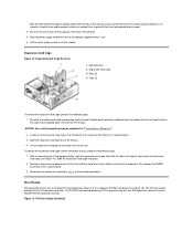
...three PCI expansion-card slots. Slide the expansion-card cage into the low-profile chassis, perform the following steps: 1. The PCI/ISA riser board provides one PCI expansion-card slot, one ISA expansion-card slot, and one shared PCI/ISA expansion-card slot. Expansion-Card Cage Removal 1 ...the chassis opening for the expansion- To replace the expansion-card cage into place. 2. Riser Boards The low-profile chassis has a standard PCI riser board (see Figure 15) or an optional PCI/ISA riser board (see Figure 16). Slide the expansion-card cage out of the chassis. 4. Remove the ...
...three PCI expansion-card slots. Slide the expansion-card cage into the low-profile chassis, perform the following steps: 1. The PCI/ISA riser board provides one PCI expansion-card slot, one ISA expansion-card slot, and one shared PCI/ISA expansion-card slot. Expansion-Card Cage Removal 1 ...the chassis opening for the expansion- To replace the expansion-card cage into place. 2. Riser Boards The low-profile chassis has a standard PCI riser board (see Figure 15) or an optional PCI/ISA riser board (see Figure 16). Slide the expansion-card cage out of the chassis. 4. Remove the ...
Service Manual
Page 11
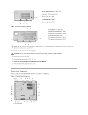
... the expansion cards installed in connector System Board Components Figure 17 shows the system board and the location of the computer. 1. System Board Components 1 Line-in the slots. 3. Lift the riser board off the expansion-card cage. To remove the riser board, perform the following steps. Remove the ... the expansion-card cage. 4. only one of these two connectors can be used at any given time. Figure 16. PCI/ISA Riser Board (Optional) 1 Auxiliary power indicator LED (AUX_LED) 2 Wakeup On LAN (WOL) connector 3 PCI expansion slot 1 (PCI1) 4 PCI expansion slot 2 (PCI2) 5 PCI ...
... the expansion cards installed in connector System Board Components Figure 17 shows the system board and the location of the computer. 1. System Board Components 1 Line-in the slots. 3. Lift the riser board off the expansion-card cage. To remove the riser board, perform the following steps. Remove the ... the expansion-card cage. 4. only one of these two connectors can be used at any given time. Figure 16. PCI/ISA Riser Board (Optional) 1 Auxiliary power indicator LED (AUX_LED) 2 Wakeup On LAN (WOL) connector 3 PCI expansion slot 1 (PCI1) 4 PCI expansion slot 2 (PCI2) 5 PCI ...
Service Manual
Page 12
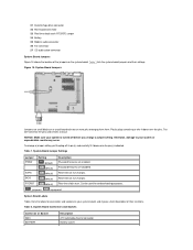
... connector 15 Control panel connector 16 External speaker connector 17 EIDE1 connector 18 EIDE2 connector 19 System board speaker 20 System board jumpers 21 Diskette/tape-drive connector 22 Riser board connector 23 Real-time clock reset (RTCRST) jumper 24 Battery 25 Modem audio connector 26 Fan ...connector 27 CD audio cable connector System Board Jumpers Figure 18 shows the location of the jumpers on a circuit board with two or more pins emerging from them. System Board Jumpers Jumpers are small blocks on the system board. NOTICE: Make sure your system or unpredictable results ...
... connector 15 Control panel connector 16 External speaker connector 17 EIDE1 connector 18 EIDE2 connector 19 System board speaker 20 System board jumpers 21 Diskette/tape-drive connector 22 Riser board connector 23 Real-time clock reset (RTCRST) jumper 24 Battery 25 Modem audio connector 26 Fan ...connector 27 CD audio cable connector System Board Jumpers Figure 18 shows the location of the jumpers on a circuit board with two or more pins emerging from them. System Board Jumpers Jumpers are small blocks on the system board. NOTICE: Make sure your system or unpredictable results ...
Service Manual
Page 13
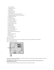
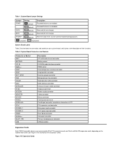
... to as LPT1 PCI expansion-card connector Main power input connector 3.3-V power input connector Riser board connector Serial port connector Primary microprocessor connector USB connectors Expansion Cards Each GX200 low-profile chassis can accommodate 32-bit PCI expansion cards and 16-bit and 8-bit ISA... expansion cards, depending on your system board, and it gives a brief description of the expansion cards. Figure 19. System Board Connectors and Sockets Connector...
... to as LPT1 PCI expansion-card connector Main power input connector 3.3-V power input connector Riser board connector Serial port connector Primary microprocessor connector USB connectors Expansion Cards Each GX200 low-profile chassis can accommodate 32-bit PCI expansion cards and 16-bit and 8-bit ISA... expansion cards, depending on your system board, and it gives a brief description of the expansion cards. Figure 19. System Board Connectors and Sockets Connector...
Service Manual
Page 14
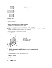
... dirt out of its outside corners, and ease it for installation, and remove the computer cover. Expansion-Card Installation 1 Expansion card 2 Card-edge connector 3 Riser board 4 Expansion-card connector 5 Expansion-card cage CAUTION: Some network cards automatically start the system when they are removing the card permanently, install a metal filler bracket...
... dirt out of its outside corners, and ease it for installation, and remove the computer cover. Expansion-Card Installation 1 Expansion card 2 Card-edge connector 3 Riser board 4 Expansion-card connector 5 Expansion-card cage CAUTION: Some network cards automatically start the system when they are removing the card permanently, install a metal filler bracket...
Service Manual
Page 16
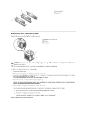
... cable from the ZIF socket. Detach and lift the microprocessor package away from its system board connector. 3. Remove the metal retaining clip that only a technically knowledgeable person perform this procedure. a. Remove the computer cover. 2. NOTE: Dell recommends that secures the heat sink assembly to the microprocessor package by gently pushing down on...
... cable from the ZIF socket. Detach and lift the microprocessor package away from its system board connector. 3. Remove the metal retaining clip that only a technically knowledgeable person perform this procedure. a. Remove the computer cover. 2. NOTE: Dell recommends that secures the heat sink assembly to the microprocessor package by gently pushing down on...
Service Manual
Page 17
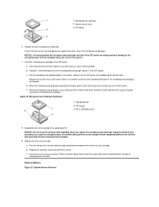
... correct holes. a. While in the ZIF socket. System Battery Removal e. When the microprocessor package is fully seated, pivot the release lever back toward the system board until it in System Setup, confirm that the system data area correctly identifies the type of the ZIF socket. Unpack the heat sink included in...
... correct holes. a. While in the ZIF socket. System Battery Removal e. When the microprocessor package is fully seated, pivot the release lever back toward the system board until it in System Setup, confirm that the system data area correctly identifies the type of the ZIF socket. Unpack the heat sink included in...
Service Manual
Page 18
...same or equivalent type recommended by carefully prying it into its corresponding tab. Disconnect all cables from the system board. 6. Carefully lift the system board out of the computer. 2. Replace the battery only with a blunt, nonconducting object such as a plastic ...screwdriver. Set the jumpers on the replacement board. 2. To replace the system board, perform the following steps: 1. Remove the computer cover. 3. System Board Removal 1 System board 2 Screw To remove the system board, perform the following steps: 1. Push down near each slot to...
...same or equivalent type recommended by carefully prying it into its corresponding tab. Disconnect all cables from the system board. 6. Carefully lift the system board out of the computer. 2. Replace the battery only with a blunt, nonconducting object such as a plastic ...screwdriver. Set the jumpers on the replacement board. 2. To replace the system board, perform the following steps: 1. Remove the computer cover. 3. System Board Removal 1 System board 2 Screw To remove the system board, perform the following steps: 1. Push down near each slot to...
Service Manual
Page 19
Replace the expansion-card cage. 8. Reset the chassis intrusion detector. Replace the 5.25-inch drive. 7. Replace the computer cover. 9. Back to the system board. 6. While in System Setup, confirm that the system data area correctly identifies the type of the system board as you slide and lock it into position (do not twist the system board). 5. 4. Reconnect all cables to Contents Page Push evenly on both sides of microprocessor installed.
Replace the expansion-card cage. 8. Reset the chassis intrusion detector. Replace the 5.25-inch drive. 7. Replace the computer cover. 9. Back to the system board. 6. While in System Setup, confirm that the system data area correctly identifies the type of the system board as you slide and lock it into position (do not twist the system board). 5. 4. Reconnect all cables to Contents Page Push evenly on both sides of microprocessor installed.
Service Manual
Page 20
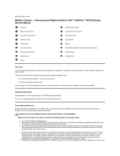
... following steps in "Precautionary Measures." If a wrist grounding strap is provided. Removing and Replacing Parts: Dell™ OptiPlex™ GX200 System Service Manual Overview System Power Supply Recommended Tools System Board Components Precautionary Measures Expansion Cards Computer Cover Riser Boards Internal View Memory Front-Panel Inserts Microprocessor/Airflow Shroud/Heat Sink Assembly Expansion-Card Cage...
... following steps in "Precautionary Measures." If a wrist grounding strap is provided. Removing and Replacing Parts: Dell™ OptiPlex™ GX200 System Service Manual Overview System Power Supply Recommended Tools System Board Components Precautionary Measures Expansion Cards Computer Cover Riser Boards Internal View Memory Front-Panel Inserts Microprocessor/Airflow Shroud/Heat Sink Assembly Expansion-Card Cage...
Service Manual
Page 21
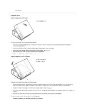
... through the padlock ring on the computer cover. Fold cables out of the computer. 5. To reset the chassis intrusion detector, perform the following steps: 1. Riser Boards). Press in place.) 4. Figure 2. Fit the three cover hooks into the rectangular slots on the two securing buttons until the cover is free to look...
... through the padlock ring on the computer cover. Fold cables out of the computer. 5. To reset the chassis intrusion detector, perform the following steps: 1. Riser Boards). Press in place.) 4. Figure 2. Fit the three cover hooks into the rectangular slots on the two securing buttons until the cover is free to look...
Service Manual
Page 22
...4 Drive interface cable 5 Expansion-card cage 6 Security cable slot 7 I/O ports and connectors 8 AC power receptacle 9 Padlock ring 10 Power supply 11 System board 12 Drive interface cable Front-Panel Inserts Figure 4. 5.25-Inch Front-Panel Insert Removal (cutaway view through top of the screen. Figure 3. If the operating...Set Secondary Drive 0 or Secondary Drive 1, as appropriate, to configure the system if it has an LS-120 SuperDisk drive: a. Run the Dell Diagnostics to reboot the system and implement the changes. 8. NOTE: If the system does not have an audio expansion card but does have an...
...4 Drive interface cable 5 Expansion-card cage 6 Security cable slot 7 I/O ports and connectors 8 AC power receptacle 9 Padlock ring 10 Power supply 11 System board 12 Drive interface cable Front-Panel Inserts Figure 4. 5.25-Inch Front-Panel Insert Removal (cutaway view through top of the screen. Figure 3. If the operating...Set Secondary Drive 0 or Secondary Drive 1, as appropriate, to configure the system if it has an LS-120 SuperDisk drive: a. Run the Dell Diagnostics to reboot the system and implement the changes. 8. NOTE: If the system does not have an audio expansion card but does have an...
Service Manual
Page 24
... of the bracket engage the mounting holes in reverse. Remove the computer cover. Then replace the screw that the two retaining tabs on the system board (see Figure 7). 4. Disconnect the control panel cable from an externally accessible drive bay, perform the following steps: 1. Note the routing of the 3.5-inch diskette drive...
... of the bracket engage the mounting holes in reverse. Remove the computer cover. Then replace the screw that the two retaining tabs on the system board (see Figure 7). 4. Disconnect the control panel cable from an externally accessible drive bay, perform the following steps: 1. Note the routing of the 3.5-inch diskette drive...
Service Manual
Page 27
... Drive n. 8. Insert a bootable diskette into the power input connector on the system board. Remove the computer cover. 2. Free the power supply from the AC power receptacle on the system board, see Figure 13). System Power Supply System Power Supply Rotation To access some components ...RELEASE->, " and rotate it upward until it is indicated by a silk-screened "1" printed on the system board. 3. Replace the computer cover. Refer to their electrical outlets, and turn on the system board, you may have to the next step. 1 Interface connector 2 Power input connector on drive 3 Lip...
... Drive n. 8. Insert a bootable diskette into the power input connector on the system board. Remove the computer cover. 2. Free the power supply from the AC power receptacle on the system board, see Figure 13). System Power Supply System Power Supply Rotation To access some components ...RELEASE->, " and rotate it upward until it is indicated by a silk-screened "1" printed on the system board. 3. Replace the computer cover. Refer to their electrical outlets, and turn on the system board, you may have to the next step. 1 Interface connector 2 Power input connector on drive 3 Lip...
Service Manual
Page 28
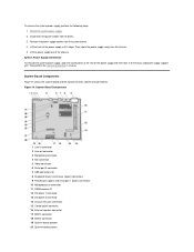
... Supply Installation To reinstall the system power supply, align the swivel points at the rear of all drives. 3. System Board Components Figure 14 shows the system board and the location of the power supply with the holes in connector 2 Line-out connector 3 Microphone connector 4 NIC ... 14 Chassis intrusion connector 15 Control panel connector 16 External speaker connector 17 EIDE1 connector 18 EIDE2 connector 19 System board speaker 20 System board jumpers System Board Components 1 Line-in the chassis and power supply support arm. Rotate the system power supply. 2. To remove ...
... Supply Installation To reinstall the system power supply, align the swivel points at the rear of all drives. 3. System Board Components Figure 14 shows the system board and the location of the power supply with the holes in connector 2 Line-out connector 3 Microphone connector 4 NIC ... 14 Chassis intrusion connector 15 Control panel connector 16 External speaker connector 17 EIDE1 connector 18 EIDE2 connector 19 System board speaker 20 System board jumpers System Board Components 1 Line-in the chassis and power supply support arm. Rotate the system power supply. 2. To remove ...
Service Manual
Page 29
...PSWD SAFE BIOS RTCRST Setting (default) (default) (default) (default) (default) Description Password features are small blocks on the system board. jumpered unjumpered System Board Labels Table 2 lists the labels for troubleshooting purposes. Table 2. Otherwise, damage to your system is turned off its pin(s) and ...carefully fit it gives a brief description of the jumpers on a circuit board with two or more pins emerging from them. Password features are disabled. Reserved (do not change a jumper setting, pull the plug off...
...PSWD SAFE BIOS RTCRST Setting (default) (default) (default) (default) (default) Description Password features are small blocks on the system board. jumpered unjumpered System Board Labels Table 2 lists the labels for troubleshooting purposes. Table 2. Otherwise, damage to your system is turned off its pin(s) and ...carefully fit it gives a brief description of the jumpers on a circuit board with two or more pins emerging from them. Password features are disabled. Reserved (do not change a jumper setting, pull the plug off...

