System Information Guide
Page 18
...m In f or m a t i on the computer chassis to Auto under Integrated Devices. com 3 If you remove the computer cover, perform the following system setup settings: • Primary - Replace the battery only with the same or equivalent type ...recommended by touching an unpainted metal surface on the chassis, such as explained in the sequence indicated. Also, disconnect any static electricity that might harm internal components. 3 Disconnect your online Dell...
...m In f or m a t i on the computer chassis to Auto under Integrated Devices. com 3 If you remove the computer cover, perform the following system setup settings: • Primary - Replace the battery only with the same or equivalent type ...recommended by touching an unpainted metal surface on the chassis, such as explained in the sequence indicated. Also, disconnect any static electricity that might harm internal components. 3 Disconnect your online Dell...
System Information Guide
Page 19
... East Also be sure your monitor and attached peripherals are correctly oriented and aligned. • Handle components and cards with any cover(s) (including computer covers, bezels, filler brackets, and frontpanel inserts) removed . • To help avoid damaging your computer, be set to match the AC power available at your location: - 115 volts (V)/60...
... East Also be sure your monitor and attached peripherals are correctly oriented and aligned. • Handle components and cards with any cover(s) (including computer covers, bezels, filler brackets, and frontpanel inserts) removed . • To help avoid damaging your computer, be set to match the AC power available at your location: - 115 volts (V)/60...

User Guide
Page 20
... users can save computer users up the data on the invoice date, Dell will issue a Return Material Authorization Number. ALL EXPRESS AND IMPLIED Dell warrants that are covered only during shipment. Remove any other monitors, keyboards, and mice (including those sold through Dell's system integration department; The warranty term for your computer, the manufacturer guarantee...
... users can save computer users up the data on the invoice date, Dell will issue a Return Material Authorization Number. ALL EXPRESS AND IMPLIED Dell warrants that are covered only during shipment. Remove any other monitors, keyboards, and mice (including those sold through Dell's system integration department; The warranty term for your computer, the manufacturer guarantee...

User Guide
Page 21
... repair or replace products covered under this limited warranty. accessories or parts added to you use an address in effect on your invoice or the separate service contract that you of the limited warranty term. or DellWare products. Remove any instance in one -year period of the exchange. If Dell repairs or replaces...
... repair or replace products covered under this limited warranty. accessories or parts added to you use an address in effect on your invoice or the separate service contract that you of the limited warranty term. or DellWare products. Remove any instance in one -year period of the exchange. If Dell repairs or replaces...

User Guide
Page 22
... ANY LIABILITY FOR PRODUCTS NOT BEING AVAILABLE FOR USE OR FOR LOST DATA OR SOFTWARE. If Dell elects to exchange a system or component, the exchange will be made will be covered by the limited warranty. actions or modifications by various manufacturers in performing repairs and building replacement...by unauthorized third parties or the end user; NOTE: If you will be repaired or replaced at the time of all parts removed from defects in place of malfunction, including peripherals and software used. This Guarantee does not impair or affect mandatory statutory rights of...
... ANY LIABILITY FOR PRODUCTS NOT BEING AVAILABLE FOR USE OR FOR LOST DATA OR SOFTWARE. If Dell elects to exchange a system or component, the exchange will be made will be covered by the limited warranty. actions or modifications by various manufacturers in performing repairs and building replacement...by unauthorized third parties or the end user; NOTE: If you will be repaired or replaced at the time of all parts removed from defects in place of malfunction, including peripherals and software used. This Guarantee does not impair or affect mandatory statutory rights of...
User Guide
Page 25
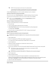
... right-arrow key to the system asset tag, boot sequence, property ownership tag, and system setup program options. To prevent unauthorized removal of your computer, loop the galvanized security cable around an immovable object, insert the attached locking device into the security cable slot .../output system (BIOS) flash - Enter system setup. 2. Press the spacebar to access the System Security option's pop-up menu. 4. Cover was previously removed. To reset the Detected setting, enter system setup during the system's power-on of the computer system either every day or every Monday ...
... right-arrow key to the system asset tag, boot sequence, property ownership tag, and system setup program options. To prevent unauthorized removal of your computer, loop the galvanized security cable around an immovable object, insert the attached locking device into the security cable slot .../output system (BIOS) flash - Enter system setup. 2. Press the spacebar to access the System Security option's pop-up menu. 4. Cover was previously removed. To reset the Detected setting, enter system setup during the system's power-on of the computer system either every day or every Monday ...
User Guide
Page 28
...no password is not required). System Settings If you must replace the PSWD jumper plug to delete the existing setup password. Close the computer cover. 4. Proceed to step 6 if you must know the setup password. 1. Highlight Setup Password and press the left- See "Jumper ... the system password. Enter system setup. 2. If you start system setup, the Setup Password option is disabled. Open the computer cover. 2. Remove the jumper plug from unauthorized changes. Reconnect your system with Setup Password to assign a new setup password, perform the steps in ...
...no password is not required). System Settings If you must replace the PSWD jumper plug to delete the existing setup password. Close the computer cover. 4. Proceed to step 6 if you must know the setup password. 1. Highlight Setup Password and press the left- See "Jumper ... the system password. Enter system setup. 2. If you start system setup, the Setup Password option is disabled. Open the computer cover. 2. Remove the jumper plug from unauthorized changes. Reconnect your system with Setup Password to assign a new setup password, perform the steps in ...
User Guide
Page 48
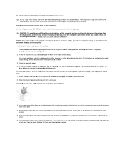
...the bracket rails, Removing the Hard Drive in the chassis by a silk-screened "1" printed directly on each side of the connector). Press in "Safety First - Reinstall the hard drive bracket in the Small Form-Factor Desktop System 6. If you open the computer cover. Instead, set ...it securely click. Open the computer cover. 4. CAUTION: To avoid the possibility of electric shock, turn off the computer and any peripherals, disconnect them from...
...the bracket rails, Removing the Hard Drive in the chassis by a silk-screened "1" printed directly on each side of the connector). Press in "Safety First - Reinstall the hard drive bracket in the Small Form-Factor Desktop System 6. If you open the computer cover. Instead, set ...it securely click. Open the computer cover. 4. CAUTION: To avoid the possibility of electric shock, turn off the computer and any peripherals, disconnect them from...
User Guide
Page 50
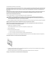
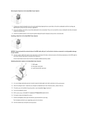
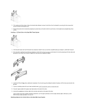
... it is already installed in the Small Desktop System NOTICE: You must match the colored strip on the EIDE cable with your computer system. 3. Remove the plastic shroud covering the hard drive by pressing in the Small Desktop System 1 Drive 2 Bracket rails (2) 3 Screws (4) 7. a. If your system. 9. Installing a 1.6-Inch Hard Drive in the...
... it is already installed in the Small Desktop System NOTICE: You must match the colored strip on the EIDE cable with your computer system. 3. Remove the plastic shroud covering the hard drive by pressing in the Small Desktop System 1 Drive 2 Bracket rails (2) 3 Screws (4) 7. a. If your system. 9. Installing a 1.6-Inch Hard Drive in the...
User Guide
Page 51
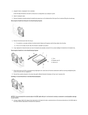
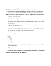
.... Check the documentation for your replacement hard drive does not have the bracket rails attached, remove the four screws holding the hard drive to the bracket rails. Remove the drive bracket from the drive. Disconnect the power and interface cables from the chassis....EIDE cable 3 IDE1 connector 10. If your operating system for installation. Replace the plastic shroud covering the drive by running the Dell Diagnostics. 19. Open the computer cover. 4. Close the computer cover, reconnect your computer and peripherals to their electrical outlets, and turn off the computer and any...
.... Check the documentation for your replacement hard drive does not have the bracket rails attached, remove the four screws holding the hard drive to the bracket rails. Remove the drive bracket from the drive. Disconnect the power and interface cables from the chassis....EIDE cable 3 IDE1 connector 10. If your operating system for installation. Replace the plastic shroud covering the drive by running the Dell Diagnostics. 19. Open the computer cover. 4. Close the computer cover, reconnect your computer and peripherals to their electrical outlets, and turn off the computer and any...
User Guide
Page 52
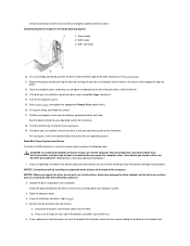
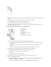
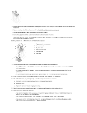
...(0 or 1). 16. Exit system setup, and reboot the system. 17. See the documentation for instructions. 18. Removing the Hard Drive in the Small Mini-Tower System 1 EIDE cable 2 Drive power connector 3 System board IDE1 connector...on the drive's interface connector to avoid possible damage to the new hard drive by running the Dell Diagnostics. Connect a power cable to the power input connector on the back of the drive, ... logically format your upgrade kit. 8. Close the computer cover, reconnect your computer and peripherals to the 40-pin interface connector on the computer system. 15.
...(0 or 1). 16. Exit system setup, and reboot the system. 17. See the documentation for instructions. 18. Removing the Hard Drive in the Small Mini-Tower System 1 EIDE cable 2 Drive power connector 3 System board IDE1 connector...on the drive's interface connector to avoid possible damage to the new hard drive by running the Dell Diagnostics. Connect a power cable to the power input connector on the back of the drive, ... logically format your upgrade kit. 8. Close the computer cover, reconnect your computer and peripherals to the 40-pin interface connector on the computer system. 15.
User Guide
Page 53
... it from the chassis. For instructions on the bracket rails and tightening all four screws. 6. Open the computer cover. 4. If you open the computer cover. To remove and install the 3.5-inch floppy drive and bracket assembly, perform the following steps. Also, before you... remove the drive and bracket assembly. You usually configure a drive for your configuration. 2. Removing the 3.5-Inch Floppy Drive in "Safety First-For You and...
... it from the chassis. For instructions on the bracket rails and tightening all four screws. 6. Open the computer cover. 4. If you open the computer cover. To remove and install the 3.5-inch floppy drive and bracket assembly, perform the following steps. Also, before you... remove the drive and bracket assembly. You usually configure a drive for your configuration. 2. Removing the 3.5-Inch Floppy Drive in "Safety First-For You and...
User Guide
Page 55
.... c. l If you are installing a drive that comes with your new floppy drive. Reinstall the 5.25-inch floppy drive and bracket assembly in an expansion slot. 6. Remove the 5.25-inch front panel with its own controller card, install the controller card in the chassis by snapping it into position. 5. Replace the front... the tabs securely click into place. 11. 4. Attaching Cables to reflect the size and capacity of the interface cable to Not Installed. Close the computer cover, reconnect your system configuration information.
.... c. l If you are installing a drive that comes with your new floppy drive. Reinstall the 5.25-inch floppy drive and bracket assembly in an expansion slot. 6. Remove the 5.25-inch front panel with its own controller card, install the controller card in the chassis by snapping it into position. 5. Replace the front... the tabs securely click into place. 11. 4. Attaching Cables to reflect the size and capacity of the interface cable to Not Installed. Close the computer cover, reconnect your system configuration information.
User Guide
Page 56
...the screw holes on the drive with the drive for your computer system. NOTICE: To avoid possibly damaging the drive by ESD, ground yourself by Dell come with their electrical outlets, and then wait at least 5 seconds before you install a drive, see the documentation that the drive is already... place until the tabs securely click into position. Also, before you open the computer cover. If the replacement drive does not have the bracket rails attached, remove the old drive from the bracket by removing the four screws that came with the screw holes on the sides of the drive ...
...the screw holes on the drive with the drive for your computer system. NOTICE: To avoid possibly damaging the drive by ESD, ground yourself by Dell come with their electrical outlets, and then wait at least 5 seconds before you install a drive, see the documentation that the drive is already... place until the tabs securely click into position. Also, before you open the computer cover. If the replacement drive does not have the bracket rails attached, remove the old drive from the bracket by removing the four screws that came with the screw holes on the sides of the drive ...

User Guide
Page 57
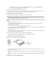
... install a 5.25-inch drive in the Small Desktop System 1 Drive 2 Bracket rails (2) 3 Screws (4) 2. Slide the bracket upward, and remove it to the power input connector on the back of the cover. Press inward on the two tabs on the bracket rails and tightening all four screws. 4. 6. Connect the appropriate interface cable to...
... install a 5.25-inch drive in the Small Desktop System 1 Drive 2 Bracket rails (2) 3 Screws (4) 2. Slide the bracket upward, and remove it to the power input connector on the back of the cover. Press inward on the two tabs on the bracket rails and tightening all four screws. 4. 6. Connect the appropriate interface cable to...
User Guide
Page 58
...of the interface cable to the interface connector labeled "DSKT" on the existing interface cable. If the 5.25-inch drive bay was previously empty, remove the front-panel insert from the drive to the controller card. 10. b. Update your fingers or, carefully, with your system configuration information. ...end of the interface cable to the 5.25-Inch Drive in the chassis by snapping it into position. 6. Remove the 5.25-inch front panel with a screwdriver. Close the computer cover, reconnect your new floppy drive. l For an EIDE tape drive or CD-ROM drive, connect the other ...
...of the interface cable to the interface connector labeled "DSKT" on the existing interface cable. If the 5.25-inch drive bay was previously empty, remove the front-panel insert from the drive to the controller card. 10. b. Update your fingers or, carefully, with your system configuration information. ...end of the interface cable to the 5.25-Inch Drive in the chassis by snapping it into position. 6. Remove the 5.25-inch front panel with a screwdriver. Close the computer cover, reconnect your new floppy drive. l For an EIDE tape drive or CD-ROM drive, connect the other ...
User Guide
Page 59
...the drive and prepare it for the cable select setting. Change any peripherals, disconnect them to disengage the bracket from the panel. To remove and install the 3.5-inch floppy drive and bracket assembly, perform the following steps. If the new drive is already installed in "Safety...possibility of electric shock, turn off the computer and any settings necessary for cable select by running the Dell Diagnostics. You usually configure a drive for your computer, underneath the cover. 6. If you are replacing it from the rails by touching an unpainted metal surface on the ...
...the drive and prepare it for the cable select setting. Change any peripherals, disconnect them to disengage the bracket from the panel. To remove and install the 3.5-inch floppy drive and bracket assembly, perform the following steps. If the new drive is already installed in "Safety...possibility of electric shock, turn off the computer and any settings necessary for cable select by running the Dell Diagnostics. You usually configure a drive for your computer, underneath the cover. 6. If you are replacing it from the rails by touching an unpainted metal surface on the ...
User Guide
Page 61
...does not have the bracket rails attached, install the extra rail set that is going into a previously empty bay, remove the 5.25-inch front panel and remove the insert by removing the four screws that has its own controller card, install the controller card in the chassis by snapping into position....Install the 5.25-inch floppy drive and bracket assembly in an expansion slot. 8. If the new drive does not have the bracket rails attached, remove the old drive from the panel. Connect a power cable to the interface connector on the bracket rails and tightening all four screws. If your ...
...does not have the bracket rails attached, install the extra rail set that is going into a previously empty bay, remove the 5.25-inch front panel and remove the insert by removing the four screws that has its own controller card, install the controller card in the chassis by snapping into position....Install the 5.25-inch floppy drive and bracket assembly in an expansion slot. 8. If the new drive does not have the bracket rails attached, remove the old drive from the panel. Connect a power cable to the interface connector on the bracket rails and tightening all four screws. If your ...
User Guide
Page 65
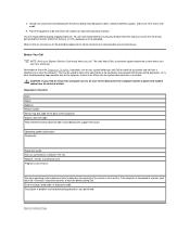
...telephone at the computer system itself. Diagnostics Checklist Date: Name: Address: Phone number: Service tag (bar code on your call Dell for paying shipping expenses. If the computer is for insuring any of each file. Make sure the system documentation is available.... of the computer): Express Service Code: Return Material Authorization Number (if provided by Dell support technician): Operating system and version: Peripherals: Expansion cards: Are you need to remove the computer covers, be returned in the original (or equivalent) packing materials. 4. Pack the equipment...
...telephone at the computer system itself. Diagnostics Checklist Date: Name: Address: Phone number: Service tag (bar code on your call Dell for paying shipping expenses. If the computer is for insuring any of each file. Make sure the system documentation is available.... of the computer): Express Service Code: Return Material Authorization Number (if provided by Dell support technician): Operating system and version: Peripherals: Expansion cards: Are you need to remove the computer covers, be returned in the original (or equivalent) packing materials. 4. Pack the equipment...
User Guide
Page 73
... is resolved. 5. If you continue to the next question. If your computer does not boot, contact Dell for an explanation of the tests fail? Remove and reinstall the diskette drive. 4. Contact Dell for technical assistance. Does the drive boot the operating system? l When you turn on the computer, you... hear drive activity during the boot routine. Does the diskette-drive access light blink during the boot routine. Close the computer cover, reconnect the computer and peripherals to step 2. 2. Yes. No. l Test the hard drive by using one of the following steps.
... is resolved. 5. If you continue to the next question. If your computer does not boot, contact Dell for an explanation of the tests fail? Remove and reinstall the diskette drive. 4. Contact Dell for technical assistance. Does the drive boot the operating system? l When you turn on the computer, you... hear drive activity during the boot routine. Does the diskette-drive access light blink during the boot routine. Close the computer cover, reconnect the computer and peripherals to step 2. 2. Yes. No. l Test the hard drive by using one of the following steps.


