Service Manual
Page 14
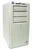
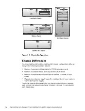
... Mini Tower Chassis OptiPlex NX1 Chassis The three OptiPlex GX1 and the OptiPlex NX1 chassis configurations differ primarily in the following expansion features: Number of expansion slots available for PCI/ISA expansion cards Number of available internal drive bays for EIDE/SCSI drives Number of available external drive bays for diskette, CD-ROM, or tape drives Physical size and...
... Mini Tower Chassis OptiPlex NX1 Chassis The three OptiPlex GX1 and the OptiPlex NX1 chassis configurations differ primarily in the following expansion features: Number of expansion slots available for PCI/ISA expansion cards Number of available internal drive bays for EIDE/SCSI drives Number of available external drive bays for diskette, CD-ROM, or tape drives Physical size and...

Service Manual
Page 16
... chapter. As a standard feature, OptiPlex GX1 and OptiPlex NX1 systems are normally used for easy BIOS upgrades using diskette files or files downloaded from Dell's home page on the World Wide Web (www.dell.com). The low-profile chassis can accommodate only one external diskette drive for example, CD-ROM drive, hard-disk drive, and so on). The system...
... chapter. As a standard feature, OptiPlex GX1 and OptiPlex NX1 systems are normally used for easy BIOS upgrades using diskette files or files downloaded from Dell's home page on the World Wide Web (www.dell.com). The low-profile chassis can accommodate only one external diskette drive for example, CD-ROM drive, hard-disk drive, and so on). The system...

Service Manual
Page 17
... audio controller is not supported by the system. To route mixed audio from an AMC-compliant adapter card to the system board, CD-ROM audio cables must be attached from the graphics controller to the device, for a line-level input to the ISA bus. A fourth...75 Hz. The 40-pin AMC connector, shown in and microphone input. The OptiPlex NX1 system contains an integrated controller and diskette drive connector but is 1600 x 1200 with a diskette drive. The OptiPlex GX1 and OptiPlex NX1 systems include an integrated highperformance 64-bit accelerated graphics port (AGP) subsystem...
... audio controller is not supported by the system. To route mixed audio from an AMC-compliant adapter card to the system board, CD-ROM audio cables must be attached from the graphics controller to the device, for a line-level input to the ISA bus. A fourth...75 Hz. The 40-pin AMC connector, shown in and microphone input. The OptiPlex NX1 system contains an integrated controller and diskette drive connector but is 1600 x 1200 with a diskette drive. The OptiPlex GX1 and OptiPlex NX1 systems include an integrated highperformance 64-bit accelerated graphics port (AGP) subsystem...
Service Manual
Page 29
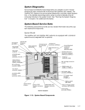
... video connector (MONITOR) line-in Chapter 2 for additional information. See "Running the System Diagnostics" in jack (LINE-IN) CD-ROM audio interface connector (CD_IN) video-memory upgrade socket (VIDEO_UPGRADE) ATI multimedia connector (AMC) riser board connector (RISER) secondary EIDE...system board jumpers primary EIDE diskette/tape drive interface connector interface connector (IDE1) (DSKT) front of the three Dell OptiPlex GX1 chassis. The OptiPlex GX1 and OptiPlex NX1 systems are available to the system board. The OptiPlex NX1 systems use server-based diagnostics, hard...
... video connector (MONITOR) line-in Chapter 2 for additional information. See "Running the System Diagnostics" in jack (LINE-IN) CD-ROM audio interface connector (CD_IN) video-memory upgrade socket (VIDEO_UPGRADE) ATI multimedia connector (AMC) riser board connector (RISER) secondary EIDE...system board jumpers primary EIDE diskette/tape drive interface connector interface connector (IDE1) (DSKT) front of the three Dell OptiPlex GX1 chassis. The OptiPlex GX1 and OptiPlex NX1 systems are available to the system board. The OptiPlex NX1 systems use server-based diagnostics, hard...
Service Manual
Page 36
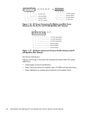
1234 P2, P3, P5, P6, P9 +5 VDC (red) common (black) common (black) +12 VDC (yellow) P4 12 34 +12 VDC (yellow) common (black) common (black) +5 VDC (red) P2, P7 1 2 34 5 6 +3.3 VDC (blue/white) +3.3 VDC (blue/white) +3.3 VDC (blue/white) common (black) common (black) common (black) Figures 1-18 through 1-22 provide the following information about DC power distribution: Power-supply connector identification Power cable connections for diskette, tape, CD-ROM, and hard-disk drives Power distribution to sockets and connectors on the system board 1-24
1234 P2, P3, P5, P6, P9 +5 VDC (red) common (black) common (black) +12 VDC (yellow) P4 12 34 +12 VDC (yellow) common (black) common (black) +5 VDC (red) P2, P7 1 2 34 5 6 +3.3 VDC (blue/white) +3.3 VDC (blue/white) +3.3 VDC (blue/white) common (black) common (black) common (black) Figures 1-18 through 1-22 provide the following information about DC power distribution: Power-supply connector identification Power cable connections for diskette, tape, CD-ROM, and hard-disk drives Power distribution to sockets and connectors on the system board 1-24

Service Manual
Page 46
...OptiPlex NX1 computers two (one ISA connector and one PCI connector share an expansion-card slot) three (one ISA connector and one 3.5-inch bay for a 3.5-inch diskette drive; one 5.25-inch bay for a diskette, tape, or CD-ROM drive one 3.5-inch bay for diskette, tape, or CD-ROM drives... 1-34 two 5.25-inch bays for a 3.5-inch diskette drive; ISA expansion-card connectors: Low-profile computers Midsize computers...
...OptiPlex NX1 computers two (one ISA connector and one PCI connector share an expansion-card slot) three (one ISA connector and one 3.5-inch bay for a 3.5-inch diskette drive; one 5.25-inch bay for a diskette, tape, or CD-ROM drive one 3.5-inch bay for diskette, tape, or CD-ROM drives... 1-34 two 5.25-inch bays for a 3.5-inch diskette drive; ISA expansion-card connectors: Low-profile computers Midsize computers...

Service Manual
Page 47
...tape, or CD-ROM drives none one bay for a 1-inch-high EIDE or SCSI harddisk drive two bays for either one or two 1-inch-high EIDE or SCSI hard-disk drives, or one 1-inch-high EIDE or SCSI hard-disk drive and one 1.6-inch-high EIDE or SCSI hard-disk drive two bays... memory required; 1600 x 1200 (16 bpp), 65535 colors, 75 Hz, minimum 8 MB video memory required System Overview 1-35 Mini tower computers OptiPlex NX1 computers one bay for a 3.5-inch diskette drive; Mini tower computers OptiPlex NX1 computers Internal hard-disk drive bays: Low-profile computers Midsize computers . . . .
...tape, or CD-ROM drives none one bay for a 1-inch-high EIDE or SCSI harddisk drive two bays for either one or two 1-inch-high EIDE or SCSI hard-disk drives, or one 1-inch-high EIDE or SCSI hard-disk drive and one 1.6-inch-high EIDE or SCSI hard-disk drive two bays... memory required; 1600 x 1200 (16 bpp), 65535 colors, 75 Hz, minimum 8 MB video memory required System Overview 1-35 Mini tower computers OptiPlex NX1 computers one bay for a 3.5-inch diskette drive; Mini tower computers OptiPlex NX1 computers Internal hard-disk drive bays: Low-profile computers Midsize computers . . . .

Service Manual
Page 75
CD-ROM drive in external bay power supply system board securing buttons (2) diskette drive drive cage for external drive internal harddisk drive chassis intrusion switch expansion-card cage front of computer Removing and Replacing Parts on the Low-Profile Chassis 4-3
CD-ROM drive in external bay power supply system board securing buttons (2) diskette drive drive cage for external drive internal harddisk drive chassis intrusion switch expansion-card cage front of computer Removing and Replacing Parts on the Low-Profile Chassis 4-3

Service Manual
Page 88
...NIC connector (ENET) video connector (MONITOR) line-in position), push down near each slot to lock it in jack (LINE-IN) CD-ROM audio interface connector (CD_IN) video-memory upgrade socket (VIDEO_UPGRADE) ATI multimedia connector (AMC) riser board connector (RISER) secondary EIDE interface ... sockets (3) (DIMM_A-DIMM_C) main power input connector (POWER_1) 3.3-V power input connector (POWER_2) system board jumpers primary EIDE diskette/tape drive interface connector interface connector (IDE1) (DSKT) front of the system board as you slide it into position (do not twist the system...
...NIC connector (ENET) video connector (MONITOR) line-in position), push down near each slot to lock it in jack (LINE-IN) CD-ROM audio interface connector (CD_IN) video-memory upgrade socket (VIDEO_UPGRADE) ATI multimedia connector (AMC) riser board connector (RISER) secondary EIDE interface ... sockets (3) (DIMM_A-DIMM_C) main power input connector (POWER_1) 3.3-V power input connector (POWER_2) system board jumpers primary EIDE diskette/tape drive interface connector interface connector (IDE1) (DSKT) front of the system board as you slide it into position (do not twist the system...

Service Manual
Page 113
... jack (MIC) line-out jack (LINE-OUT) optional NIC connector (ENET) video connector (MONITOR) line-in jack (LINE-IN) CD-ROM audio interface connector (CD_IN) video-memory upgrade socket (VIDEO_UPGRADE) ATI multimedia connector (AMC) riser board connector (RISER) secondary EIDE interface ...sockets (3) (DIMM_A-DIMM_C) main power input connector (POWER_1) 3.3-V power input connector (POWER_2) system board jumpers primary EIDE diskette/tape drive interface connector interface connector (IDE1) (DSKT) front of the system board as you slide it into position (do not twist the system...
... jack (MIC) line-out jack (LINE-OUT) optional NIC connector (ENET) video connector (MONITOR) line-in jack (LINE-IN) CD-ROM audio interface connector (CD_IN) video-memory upgrade socket (VIDEO_UPGRADE) ATI multimedia connector (AMC) riser board connector (RISER) secondary EIDE interface ...sockets (3) (DIMM_A-DIMM_C) main power input connector (POWER_1) 3.3-V power input connector (POWER_2) system board jumpers primary EIDE diskette/tape drive interface connector interface connector (IDE1) (DSKT) front of the system board as you slide it into position (do not twist the system...

Service Manual
Page 139
Push evenly on both sides of computer control panel connector (PANEL) diskette/tape drive interface connector (DSKT) primary EIDE interface connector (IDE1) secondary EIDE interface connector (IDE2) system board jumpers video-memory ATI ...(stacked) (PARALLEL/SERIAL1) keyboard/mouse connectors (stacked) (KYBD/MOUSE) USB connectors (2) (USB) serial port 2 connector (SERIAL2) microprocessor fan connector (FAN) CD-ROM audio interface connector (CD_IN) video connector (MONITOR) optional integrated NIC connector (ENET) microphone jack (MIC) audio line-out jack (LINE-OUT) audio line-in ...
Push evenly on both sides of computer control panel connector (PANEL) diskette/tape drive interface connector (DSKT) primary EIDE interface connector (IDE1) secondary EIDE interface connector (IDE2) system board jumpers video-memory ATI ...(stacked) (PARALLEL/SERIAL1) keyboard/mouse connectors (stacked) (KYBD/MOUSE) USB connectors (2) (USB) serial port 2 connector (SERIAL2) microprocessor fan connector (FAN) CD-ROM audio interface connector (CD_IN) video connector (MONITOR) optional integrated NIC connector (ENET) microphone jack (MIC) audio line-out jack (LINE-OUT) audio line-in ...

Service Manual
Page 157
... line-out jack (LINE-OUT) optional NIC connector (ENET) video connector (MONITOR) line-in jack (LINE-IN) CD-ROM audio interface connector (CD_IN) video-memory upgrade socket (VIDEO_UPGRADE) ATI multimedia connector (AMC) riser board connector (RISER) ...DIMM sockets (3) (DIMM_A-DIMM_C) main power input connector (POWER_1) 3.3-V power input connector (POWER_2) system board jumpers primary EIDE diskette/tape drive interface connector interface connector (IDE1) (DSKT) front of computer battery socket (BATTERY) chassis-intrusion switch connector (INTRUSION) control panel connector ...
... line-out jack (LINE-OUT) optional NIC connector (ENET) video connector (MONITOR) line-in jack (LINE-IN) CD-ROM audio interface connector (CD_IN) video-memory upgrade socket (VIDEO_UPGRADE) ATI multimedia connector (AMC) riser board connector (RISER) ...DIMM sockets (3) (DIMM_A-DIMM_C) main power input connector (POWER_1) 3.3-V power input connector (POWER_2) system board jumpers primary EIDE diskette/tape drive interface connector interface connector (IDE1) (DSKT) front of computer battery socket (BATTERY) chassis-intrusion switch connector (INTRUSION) control panel connector ...

Service Manual
Page 166
... each of system board memory that requires special addressing is activated. OptiPlex NX1 chassis supports only one harddisk drive and no CD-ROM drive or tape drive. Identifies type of the new drive, enter parameters directly. If none of the supported drive types matches the parameters of diskette drives installed. Indicates processor speed at which system boots-the processor...
... each of system board memory that requires special addressing is activated. OptiPlex NX1 chassis supports only one harddisk drive and no CD-ROM drive or tape drive. Identifies type of the new drive, enter parameters directly. If none of the supported drive types matches the parameters of diskette drives installed. Indicates processor speed at which system boots-the processor...

Service Manual
Page 167
... want the system to Diskette First (the default option), Hard Disk Only, CD-ROM First, or Device List. The time uses the 24-hour format. With the Power Management category enabled, DPMS monitors and most EIDE drives automatically switch into low-power mode during periods of system's password security feature.... time you to set the system password to Not Detected. NOTE: Not all EIDE hard-disk drives support this feature for a drive that does not support it may cause the EIDE drive to become inoperable until the system is restarted and the Power Management category is required to reset ...
... want the system to Diskette First (the default option), Hard Disk Only, CD-ROM First, or Device List. The time uses the 24-hour format. With the Power Management category enabled, DPMS monitors and most EIDE drives automatically switch into low-power mode during periods of system's password security feature.... time you to set the system password to Not Detected. NOTE: Not all EIDE hard-disk drives support this feature for a drive that does not support it may cause the EIDE drive to become inoperable until the system is restarted and the Power Management category is required to reset ...

Service Manual
Page 169
...devices in the Boot Device Priority category according to the original Boot Device Priority category settings, press . If you want the SCSI drive 0 to be drive C, you must move the SCSI adapter item to boot from, the system first considers the order of the devices listed under ...system: Boot Device Priority Exclude From Boot Device Priority Device Controller Priority The Boot Device Priority category lists all bootable devices (hard-disk drives, CD-ROM drives, and so on) that the highest-priority controller is at the top of the Device Controller Priority category and the highest-priority ...
...devices in the Boot Device Priority category according to the original Boot Device Priority category settings, press . If you want the SCSI drive 0 to be drive C, you must move the SCSI adapter item to boot from, the system first considers the order of the devices listed under ...system: Boot Device Priority Exclude From Boot Device Priority Device Controller Priority The Boot Device Priority category lists all bootable devices (hard-disk drives, CD-ROM drives, and so on) that the highest-priority controller is at the top of the Device Controller Priority category and the highest-priority ...

Service Manual
Page 171
... power supply, 1-7 ATI multimedia channel, 1-5 audio connectors, 1-7 controller, 1-5 battery removal low-profile computer, 4-20 midsize computer, 5-23 mini tower computer, 6-25 OptiPlex NX1 computer, 7-17 beep codes, 3-1 BIOS, flash ROM, 1-4 cabling, verification, 2-2 CD-ROM drives removal, low-profile computer, 4-9 removal, midsize computer, 5-11 removal, mini tower computer, 6-12 chassis configurations, 1-2 differences, 1-2 intrusion detection, 1-6 similarities, 1-3 chassis...
... power supply, 1-7 ATI multimedia channel, 1-5 audio connectors, 1-7 controller, 1-5 battery removal low-profile computer, 4-20 midsize computer, 5-23 mini tower computer, 6-25 OptiPlex NX1 computer, 7-17 beep codes, 3-1 BIOS, flash ROM, 1-4 cabling, verification, 2-2 CD-ROM drives removal, low-profile computer, 4-9 removal, midsize computer, 5-11 removal, mini tower computer, 6-12 chassis configurations, 1-2 differences, 1-2 intrusion detection, 1-6 similarities, 1-3 chassis...

Service Manual
Page 173
... assignments, 1-20 documentation, online, 1-16 drives 3.5-inch diskette drive removal, low-profile computer, 4-8 3.5-inch diskette drive removal, midsize computer, 5-10 3.5-inch diskette drive removal, mini tower computer, 6-12 drives (continued) CD-ROM drive removal, low-profile computer, 4-9 CD-ROM drive removal, midsize computer, 5-11 CD-ROM drive removal, mini tower computer, 6-12 external diskette-drive kit, OptiPlex NX1 computer, 2-9 hard-disk drive removal, low-profile computer, 4-10...
... assignments, 1-20 documentation, online, 1-16 drives 3.5-inch diskette drive removal, low-profile computer, 4-8 3.5-inch diskette drive removal, midsize computer, 5-10 3.5-inch diskette drive removal, mini tower computer, 6-12 drives (continued) CD-ROM drive removal, low-profile computer, 4-9 CD-ROM drive removal, midsize computer, 5-11 CD-ROM drive removal, mini tower computer, 6-12 external diskette-drive kit, OptiPlex NX1 computer, 2-9 hard-disk drive removal, low-profile computer, 4-10...


