Quick Reference Guide
Page 41
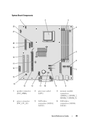
System Board Components 1 2 22 21 3 4 20 19 5 18 6 17 16 7 15 14 13 12 11 10 9 8 1 speaker connector (INT_SPKR) 4 power connector (PW_12V_A1) 2 processor socket (CPU) 5 SATA drive connectors (SATA2, SATA3) 3 memory module connectors (DIMM_1, DIMM_2, DIMM_3, DIMM_4) 6 SATA drive connectors (SATA0, SATA1) Quick Reference Guide 41
System Board Components 1 2 22 21 3 4 20 19 5 18 6 17 16 7 15 14 13 12 11 10 9 8 1 speaker connector (INT_SPKR) 4 power connector (PW_12V_A1) 2 processor socket (CPU) 5 SATA drive connectors (SATA2, SATA3) 3 memory module connectors (DIMM_1, DIMM_2, DIMM_3, DIMM_4) 6 SATA drive connectors (SATA0, SATA1) Quick Reference Guide 41
Quick Reference Guide
Page 45
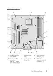
System Board Components 1 20 2 3 19 4 18 17 5 16 6 15 7 14 13 12 11 10 9 1 speaker connector (INT_SPKR) 2 processor socket (CPU) 4 memory module 5 power connector connectors (POWER1) (DIMM_1, DIMM_2, DIMM_3, DIMM_4) 8 3 power connector (PW_12V_A1) 6 SATA drive connectors (SATA0, SATA1, SATA2) Quick Reference Guide 45
System Board Components 1 20 2 3 19 4 18 17 5 16 6 15 7 14 13 12 11 10 9 1 speaker connector (INT_SPKR) 2 processor socket (CPU) 4 memory module 5 power connector connectors (POWER1) (DIMM_1, DIMM_2, DIMM_3, DIMM_4) 8 3 power connector (PW_12V_A1) 6 SATA drive connectors (SATA0, SATA1, SATA2) Quick Reference Guide 45
Quick Reference Guide
Page 49
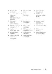
...) 4 memory module 5 power connector connectors (POWER1) (DIMM_1, DIMM_2, DIMM_3, DIMM_4) 7 front-panel connector (FRONTPANEL) 8 fan connector (FAN_HDD) 10 CMOS reset jumper 11 battery socket (RTCRST) (BATTERY) 13 standby 14 PCI Express x16 (AUX_PWR_LED) connector (SLOT1) 16 password jumper (PSWD) 17 serial connector (PS2/SER2) 19 optional DVI-card connector (...
...) 4 memory module 5 power connector connectors (POWER1) (DIMM_1, DIMM_2, DIMM_3, DIMM_4) 7 front-panel connector (FRONTPANEL) 8 fan connector (FAN_HDD) 10 CMOS reset jumper 11 battery socket (RTCRST) (BATTERY) 13 standby 14 PCI Express x16 (AUX_PWR_LED) connector (SLOT1) 16 password jumper (PSWD) 17 serial connector (PS2/SER2) 19 optional DVI-card connector (...
User's Guide
Page 34
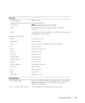
...-pin connector Intrusion switch 3-pin connector Speaker 5-pin connector Memory modules four 240-pin connector Power 12V 4-pin connector Power 24-pin connector Battery 2-pin socket Front panel 40-pin connector Key Combinations or in Microsoft® Windows® XP and Windows Vista®, brings up only) Mini Tower Computer 34...
...-pin connector Intrusion switch 3-pin connector Speaker 5-pin connector Memory modules four 240-pin connector Power 12V 4-pin connector Power 24-pin connector Battery 2-pin socket Front panel 40-pin connector Key Combinations or in Microsoft® Windows® XP and Windows Vista®, brings up only) Mini Tower Computer 34...
User's Guide
Page 83
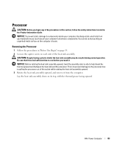
... procedures in this section, follow the safety instructions located in "Before You Begin" on page 19. 2 Loosen the captive screw on each side of the socket while rotating the heat sink assembly upward. 3 Rotate the heat sink assembly upward, and remove it from your computer's electronic components. Removing the Processor 1 Follow...
... procedures in this section, follow the safety instructions located in "Before You Begin" on page 19. 2 Loosen the captive screw on each side of the socket while rotating the heat sink assembly upward. 3 Rotate the heat sink assembly upward, and remove it from your computer's electronic components. Removing the Processor 1 Follow...
User's Guide
Page 85
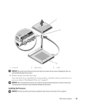
... on the back of the pins when you remove the processor. Leave the release lever extended in the release position so that the socket is ready for the new processor and go to "Installing the Processor" on the pins can permanently damage the processor. 5 Remove ...the processor from the socket. 1 2 3 1 processor 2 release lever 3 socket NOTICE: Be careful not to bend any thermal grease on the processor pins. Mini Tower Computer 85 NOTICE: After removing the processor...
... on the back of the pins when you remove the processor. Leave the release lever extended in the release position so that the socket is ready for the new processor and go to "Installing the Processor" on the pins can permanently damage the processor. 5 Remove ...the processor from the socket. 1 2 3 1 processor 2 release lever 3 socket NOTICE: Be careful not to bend any thermal grease on the processor pins. Mini Tower Computer 85 NOTICE: After removing the processor...
User's Guide
Page 86
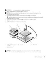
... not fully extended, move it to bend any of the processor and socket. 3 2 1 1 socket and processor pin-1 indicator 4 processor socket 2 processor 4 3 release lever NOTICE: To avoid damage, ensure that the processor aligns properly with the socket, and do not bend any of the processor pins. Mini Tower Computer 86...permanently damage the processor. 2 Unpack the new processor, being careful not to bend any of the pins. 1 Follow the procedures in the socket to avoid permanent damage to the processor and the computer when you turn on the computer. 3 If the release lever on page 19. ...
... not fully extended, move it to bend any of the processor and socket. 3 2 1 1 socket and processor pin-1 indicator 4 processor socket 2 processor 4 3 release lever NOTICE: To avoid damage, ensure that the processor aligns properly with the socket, and do not bend any of the processor pins. Mini Tower Computer 86...permanently damage the processor. 2 Unpack the new processor, being careful not to bend any of the pins. 1 Follow the procedures in the socket to avoid permanent damage to the processor and the computer when you turn on the computer. 3 If the release lever on page 19. ...
User's Guide
Page 87
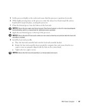
... the thermal grease from the bottom of the processor. NOTICE: Ensure that the CPU and audio cables are properly aligned with the holes in the socket and ensure that the processor is positioned correctly. 6 While lightly pressing down towards the computer base and ensure that you apply new thermal grease. NOTICE...
... the thermal grease from the bottom of the processor. NOTICE: Ensure that the CPU and audio cables are properly aligned with the holes in the socket and ensure that the processor is positioned correctly. 6 While lightly pressing down towards the computer base and ensure that you apply new thermal grease. NOTICE...
User's Guide
Page 102
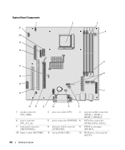
System Board Components 1 21 20 19 18 17 16 15 14 2 3 DIMM 1 DIMM 2 DIMM 3 DIMM 4 4 SATA 2 5 6 SATA 1 SATA 0 7 13 12 11 10 9 8 1 speaker connector (INT_SPKR) 4 power connector (PW_12V_A1) 7 front-panel connector (FRONTPANEL) 10 battery socket (BATTERY) 2 processor socket (CPU) 3 memory module connectors (DIMM_1, DIMM_2, DIMM_3, DIMM_4) 5 power connector (POWER1) 6 SATA drive connectors (SATA0, SATA1, SATA2) 8 intrusion switch connector (INTRUDER) 9 CMOS reset jumper (RTCRST) 11 internal USB (USB1) 12 PCI Express x16 connector (SLOT1) 102 Desktop Computer
System Board Components 1 21 20 19 18 17 16 15 14 2 3 DIMM 1 DIMM 2 DIMM 3 DIMM 4 4 SATA 2 5 6 SATA 1 SATA 0 7 13 12 11 10 9 8 1 speaker connector (INT_SPKR) 4 power connector (PW_12V_A1) 7 front-panel connector (FRONTPANEL) 10 battery socket (BATTERY) 2 processor socket (CPU) 3 memory module connectors (DIMM_1, DIMM_2, DIMM_3, DIMM_4) 5 power connector (POWER1) 6 SATA drive connectors (SATA0, SATA1, SATA2) 8 intrusion switch connector (INTRUDER) 9 CMOS reset jumper (RTCRST) 11 internal USB (USB1) 12 PCI Express x16 connector (SLOT1) 102 Desktop Computer

User's Guide
Page 108
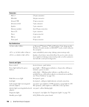
... connector two 124-pin connectors 164-pin connector 10-pin connector 3-pin connector 5-pin connector four 240-pin connector 4-pin connector 24-pin connector 2-pin socket 40-pin connector Key Combinations or or in and line-out; push button 108 Desktop Computer in MS-DOS® mode, restarts (reboots) the computer...
... connector two 124-pin connectors 164-pin connector 10-pin connector 3-pin connector 5-pin connector four 240-pin connector 4-pin connector 24-pin connector 2-pin socket 40-pin connector Key Combinations or or in and line-out; push button 108 Desktop Computer in MS-DOS® mode, restarts (reboots) the computer...

User's Guide
Page 179
... hot during normal operation. NOTICE: Before rotating the heat sink assembly upward, twist the assembly side to side to pulling the processor out of the socket while rotating the heat sink assembly upward. 3 Rotate the heat sink assembly upward, and remove the assembly from your body before you touch any of...
... hot during normal operation. NOTICE: Before rotating the heat sink assembly upward, twist the assembly side to side to pulling the processor out of the socket while rotating the heat sink assembly upward. 3 Rotate the heat sink assembly upward, and remove the assembly from your body before you touch any of...

User's Guide
Page 181
... be careful not to get any of the pins when you remove the processor from the socket. Thermal grease on the processor pins. Leave the release lever extended in the release position so that the socket is ready for the new processor, and go to "Installing the Processor" on page 182.... Desktop Computer 181 1 2 3 1 processor 2 release lever 3 socket NOTICE: Be careful not to bend any thermal grease on the pins can ...
... be careful not to get any of the pins when you remove the processor from the socket. Thermal grease on the processor pins. Leave the release lever extended in the release position so that the socket is ready for the new processor, and go to "Installing the Processor" on page 182.... Desktop Computer 181 1 2 3 1 processor 2 release lever 3 socket NOTICE: Be careful not to bend any thermal grease on the pins can ...

User's Guide
Page 182
... to bend any of the pins when you unpack the processor. Bending the pins can permanently damage the processor. 1 Follow the procedures in the socket to avoid permanent damage to the processor and the computer when you replace the processor. Bending the pins can permanently damage the processor. 2 Unpack... the new processor, being careful not to bend any of the pins when you turn on the computer. 3 If the release lever on the socket is not fully extended, move it to bend any of the processor pins. Installing the Processor NOTICE: Ground yourself by touching an unpainted metal surface...
... to bend any of the pins when you unpack the processor. Bending the pins can permanently damage the processor. 1 Follow the procedures in the socket to avoid permanent damage to the processor and the computer when you replace the processor. Bending the pins can permanently damage the processor. 2 Unpack... the new processor, being careful not to bend any of the pins when you turn on the computer. 3 If the release lever on the socket is not fully extended, move it to bend any of the processor pins. Installing the Processor NOTICE: Ground yourself by touching an unpainted metal surface...

User's Guide
Page 183
... install the processor. 5 Set the processor lightly in the system board. NOTICE: Ensure that the two captive screws are properly aligned with the socket, and do not use excessive force when you apply new thermal grease. NOTICE: To avoid damage, ensure that the processor aligns properly with the... holes in the socket and ensure that the heat sink assembly is a requirement for optimal processor operation. 8 Apply the new thermal grease to the top of the...
... install the processor. 5 Set the processor lightly in the system board. NOTICE: Ensure that the two captive screws are properly aligned with the socket, and do not use excessive force when you apply new thermal grease. NOTICE: To avoid damage, ensure that the processor aligns properly with the... holes in the socket and ensure that the heat sink assembly is a requirement for optimal processor operation. 8 Apply the new thermal grease to the top of the...
User's Guide
Page 196
... Front panel 124-pin connector 164-pin connector 10-pin connector 3-pin connector 5-pin connector four 240-pin connectors 4-pin connector 24-pin connector 2-pin socket 40-pin connector Key Combinations or or in MS-DOS® mode, restarts (reboots) the computer starts embedded system setup (during system start-up only...
... Front panel 124-pin connector 164-pin connector 10-pin connector 3-pin connector 5-pin connector four 240-pin connectors 4-pin connector 24-pin connector 2-pin socket 40-pin connector Key Combinations or or in MS-DOS® mode, restarts (reboots) the computer starts embedded system setup (during system start-up only...

User's Guide
Page 243
... upward. NOTICE: Before rotating the heat sink assembly upward, twist the assembly side to side to the processor from pulling the processor out of the socket while rotating the heat sink assembly upward. 5 Rotate the heat sink assembly upward, and remove the assembly from your body before you touch any of...
... upward. NOTICE: Before rotating the heat sink assembly upward, twist the assembly side to side to the processor from pulling the processor out of the socket while rotating the heat sink assembly upward. 5 Rotate the heat sink assembly upward, and remove the assembly from your body before you touch any of...

User's Guide
Page 245
...the Processor" on the processor pins. NOTICE: Be careful not to get any of the pins when you replace the processor from the socket. NOTICE: After removing the processor, be careful not to bend any thermal grease on page 245. Bending the pins can permanently damage the... processor. Bending the pins can permanently damage the processor. 7 Remove the processor from the socket. Leave the release lever extended in "Before You Begin" on the back of the computer. Small Form Factor Computer 245 Installing the Processor...
...the Processor" on the processor pins. NOTICE: Be careful not to get any of the pins when you replace the processor from the socket. NOTICE: After removing the processor, be careful not to bend any thermal grease on page 245. Bending the pins can permanently damage the... processor. Bending the pins can permanently damage the processor. 7 Remove the processor from the socket. Leave the release lever extended in "Before You Begin" on the back of the computer. Small Form Factor Computer 245 Installing the Processor...

User's Guide
Page 246
...can permanently damage the processor. 2 Unpack the new processor, being careful not to bend any of the processor and socket. 3 2 1 4 1 socket and processor pin-1 indicator 4 processor socket 2 processor 3 release lever NOTICE: To avoid damage, ensure that the processor is a requirement for ensuring adequate ...thermal bonding, which is positioned correctly. 6 While lightly pressing down on the socket is not fully extended, move it snaps into place, securing the processor. 7 Clean the thermal grease from the bottom of the...
...can permanently damage the processor. 2 Unpack the new processor, being careful not to bend any of the processor and socket. 3 2 1 4 1 socket and processor pin-1 indicator 4 processor socket 2 processor 3 release lever NOTICE: To avoid damage, ensure that the processor is a requirement for ensuring adequate ...thermal bonding, which is positioned correctly. 6 While lightly pressing down on the socket is not fully extended, move it snaps into place, securing the processor. 7 Clean the thermal grease from the bottom of the...
User's Guide
Page 284
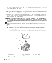
...connector and pry the battery it up out of the securing tabs at the negative side of the connector. 1 2 3 4 1 system battery 4 battery socket tab 284 Battery 2 positive side of the connector. 1 If you have not already done so, make a copy of your configuration information, found in ...computers or "System Board Components" on page 190 for small form factor computers). Ensure that the object is inserted between the battery and the socket before you must firmly support the connector while removing the battery. 5 Remove the system battery. a Support the battery connector by breaking circuit...
...connector and pry the battery it up out of the securing tabs at the negative side of the connector. 1 2 3 4 1 system battery 4 battery socket tab 284 Battery 2 positive side of the connector. 1 If you have not already done so, make a copy of your configuration information, found in ...computers or "System Board Components" on page 190 for small form factor computers). Ensure that the object is inserted between the battery and the socket before you must firmly support the connector while removing the battery. 5 Remove the system battery. a Support the battery connector by breaking circuit...
User's Guide
Page 293
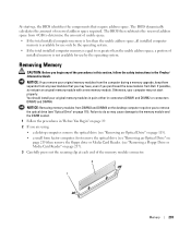
The BIOS then subtracts the reserved address space from Dell. You should install your computer may not start -up, the BIOS identifies the components that you may have, even if you begin any of the ... the total installed computer memory is less than the usable address space, a portion of installed memory is equal to the memory module and the DIMM socket. 1 Follow the procedures in "Before You Begin" on page 19. 2 If you to remove the optical drive (see "Removing a Floppy Drive or Media Card Reader...
The BIOS then subtracts the reserved address space from Dell. You should install your computer may not start -up, the BIOS identifies the components that you may have, even if you begin any of the ... the total installed computer memory is less than the usable address space, a portion of installed memory is equal to the memory module and the DIMM socket. 1 Follow the procedures in "Before You Begin" on page 19. 2 If you to remove the optical drive (see "Removing a Floppy Drive or Media Card Reader...


