Quick Reference Guide
Page 3
...Connectors 30 Removing the Computer Cover 32 Before You Begin 32 Mini Tower Computer 34 Desktop Computer 36 Small Form Factor Computer 38 Inside Your Computer 39 Mini Tower Computer 39 Desktop Computer 43 Small Form Factor Computer 47 Contents 3 Back View 23 Desktop Computer - Front View 14 Mini Tower Computer - Back... Finding Information 5 Setting Up Your Computer 10 System Views 14 Mini Tower Computer - Front View 21 Desktop Computer - Front View . . . . 26 Small Form Factor Computer - Back-Panel Connectors 19 Desktop Computer - Back-Panel Connectors . . 24...
...Connectors 30 Removing the Computer Cover 32 Before You Begin 32 Mini Tower Computer 34 Desktop Computer 36 Small Form Factor Computer 38 Inside Your Computer 39 Mini Tower Computer 39 Desktop Computer 43 Small Form Factor Computer 47 Contents 3 Back View 23 Desktop Computer - Front View 14 Mini Tower Computer - Back... Finding Information 5 Setting Up Your Computer 10 System Views 14 Mini Tower Computer - Front View 21 Desktop Computer - Front View . . . . 26 Small Form Factor Computer - Back-Panel Connectors 19 Desktop Computer - Back-Panel Connectors . . 24...
Quick Reference Guide
Page 26
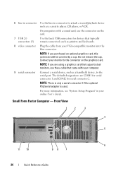
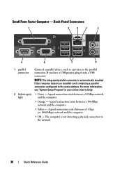
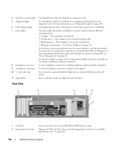
... card, use the y-cable that typically remain connected, such as printers and keyboards. 8 video connector Plug the cable from your monitor to the serial port. Small Form Factor Computer - On computers with your computer. 9 serial connector Connect a serial device, such as a cassette player, CD player, or VCR. For more information, see "System Setup...
... card, use the y-cable that typically remain connected, such as printers and keyboards. 8 video connector Plug the cable from your monitor to the serial port. Small Form Factor Computer - On computers with your computer. 9 serial connector Connect a serial device, such as a cassette player, CD player, or VCR. For more information, see "System Setup...
Quick Reference Guide
Page 29
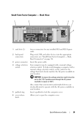
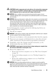
... to lock the computer cover. Plug serial, USB, and other devices into the appropriate connectors (see "Small Form Factor Computer - Insert the power cable. Also, ensure that most closely matches the AC power available in your location. Small Form Factor Computer - NOTICE: In Japan, the voltage selection switch must be equipped with the AC power available...
... to lock the computer cover. Plug serial, USB, and other devices into the appropriate connectors (see "Small Form Factor Computer - Insert the power cable. Also, ensure that most closely matches the AC power available in your location. Small Form Factor Computer - NOTICE: In Japan, the voltage selection switch must be equipped with the AC power available...
Quick Reference Guide
Page 30
Small Form Factor Computer - For more information, see "System Setup Program" in your online User's Guide. 2 link integrity • Green - NOTE: The integrated parallel connector is not detecting a ...
Small Form Factor Computer - For more information, see "System Setup Program" in your online User's Guide. 2 link integrity • Green - NOTE: The integrated parallel connector is not detecting a ...
Quick Reference Guide
Page 33
... Tower Computer" on page 34). • Remove the desktop computer cover (see "Desktop Computer" on page 36). • Remove the small form factor computer cover (see the documentation that could harm internal components. if you are correctly oriented and aligned. NOTICE: Before touching anything inside the ... by your computer and all attached devices from the electrical outlet before you connect a cable, ensure that is not authorized by Dell is not covered by its metal mounting bracket. CAUTION: Handle components and cards with locking tabs; To avoid damaging the computer...
... Tower Computer" on page 34). • Remove the desktop computer cover (see "Desktop Computer" on page 36). • Remove the small form factor computer cover (see the documentation that could harm internal components. if you are correctly oriented and aligned. NOTICE: Before touching anything inside the ... by your computer and all attached devices from the electrical outlet before you connect a cable, ensure that is not authorized by Dell is not covered by its metal mounting bracket. CAUTION: Handle components and cards with locking tabs; To avoid damaging the computer...
Quick Reference Guide
Page 38
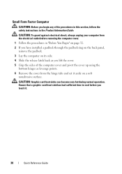
.... 5 Grip the sides of the computer cover and pivot the cover up using the bottom hinges as you touch it aside on a soft nonabrasive surface. Small Form Factor Computer CAUTION: Before you begin any of the procedures in this section, follow the safety instructions in "Before You Begin" on page 32. 2 If you...
.... 5 Grip the sides of the computer cover and pivot the cover up using the bottom hinges as you touch it aside on a soft nonabrasive surface. Small Form Factor Computer CAUTION: Before you begin any of the procedures in this section, follow the safety instructions in "Before You Begin" on page 32. 2 If you...
Quick Reference Guide
Page 47
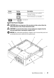
... computer cover to ensure that you begin any of the procedures in this section, follow the safety instructions in the Product Information Guide. jumpered unjumpered Small Form Factor Computer CAUTION: Before you do not accidentally disconnect cables from the electrical outlet before removing the computer cover.
... computer cover to ensure that you begin any of the procedures in this section, follow the safety instructions in the Product Information Guide. jumpered unjumpered Small Form Factor Computer CAUTION: Before you do not accidentally disconnect cables from the electrical outlet before removing the computer cover.
Quick Reference Guide
Page 50
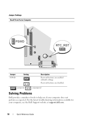
Password features are enabled (default setting). jumpered unjumpered Solving Problems Dell provides a number of tools to help you if your computer, see the Dell Support website at support.dell.com. 50 Quick Reference Guide Jumper Settings Small Form Factor Computer Jumper PSWD Setting Description Password features are disabled. For the latest troubleshooting information available for your computer does not perform as expected.
Password features are enabled (default setting). jumpered unjumpered Solving Problems Dell provides a number of tools to help you if your computer, see the Dell Support website at support.dell.com. 50 Quick Reference Guide Jumper Settings Small Form Factor Computer Jumper PSWD Setting Description Password features are disabled. For the latest troubleshooting information available for your computer does not perform as expected.

User's Guide
Page 5
Processor 179 Removing the Processor 179 Installing the Processor 182 5 Small Form Factor Computer 185 About Your Small Form Factor Computer 185 Front View 185 Back View 186 Back-Panel Connectors 187 Inside Your Computer 188 System Board Components 190 Small Form Factor Computer (Model # DCCY) Specifications 193 I/O Panel 199 Removing the I/O Panel 199 Replacing the I/O Panel 201 Removing the...
Processor 179 Removing the Processor 179 Installing the Processor 182 5 Small Form Factor Computer 185 About Your Small Form Factor Computer 185 Front View 185 Back View 186 Back-Panel Connectors 187 Inside Your Computer 188 System Board Components 190 Small Form Factor Computer (Model # DCCY) Specifications 193 I/O Panel 199 Removing the I/O Panel 199 Replacing the I/O Panel 201 Removing the...
User's Guide
Page 6
6 Advanced Features 249 LegacySelect Technology Control 249 Manageability 249 Alert Standard Format 249 Dell OpenManage™ IT Assistant 250 Dell OpenManage Client Instrumentation 250 Security 250 Chassis Intrusion Detection 250 Option Settings 251 Padlock Ring and Security Cable...Setup Options 258 Booting to a USB Device 264 Memory Key 264 Floppy Drive 264 Jumper Settings 265 Mini Tower, Desktop, and Small Form Factor Computers 265 Clearing Forgotten Passwords 265 Clearing CMOS Settings 266 HyperTransport™ and Dual-Core Technology 267 Power Management 267 About RAID ...
6 Advanced Features 249 LegacySelect Technology Control 249 Manageability 249 Alert Standard Format 249 Dell OpenManage™ IT Assistant 250 Dell OpenManage Client Instrumentation 250 Security 250 Chassis Intrusion Detection 250 Option Settings 251 Padlock Ring and Security Cable...Setup Options 258 Booting to a USB Device 264 Memory Key 264 Floppy Drive 264 Jumper Settings 265 Mini Tower, Desktop, and Small Form Factor Computers 265 Clearing Forgotten Passwords 265 Clearing CMOS Settings 266 HyperTransport™ and Dual-Core Technology 267 Power Management 267 About RAID ...
User's Guide
Page 7
...; Technology 275 7 Chassis Intrusion Switch 277 Removing the Chassis Intrusion Switch 277 Mini Tower Computer 278 Desktop Computer 279 Small Form Factor Computer 280 Replacing the Chassis Intrusion Switch 280 Resetting the Chassis Intrusion Detector 280 8 Battery 283 Replacing the Battery 283... 9 Replacing the System Board 287 Removing the System Board: Mini Tower, Desktop, and Small Form Factor Computers 287 Replacing the System Board: Mini Tower, Desktop, and Small Form Factor Computers 290 10 Memory 291 DDR2 Memory Overview 291 Addressing Memory With 4-GB or Greater ...
...; Technology 275 7 Chassis Intrusion Switch 277 Removing the Chassis Intrusion Switch 277 Mini Tower Computer 278 Desktop Computer 279 Small Form Factor Computer 280 Replacing the Chassis Intrusion Switch 280 Resetting the Chassis Intrusion Detector 280 8 Battery 283 Replacing the Battery 283... 9 Replacing the System Board 287 Removing the System Board: Mini Tower, Desktop, and Small Form Factor Computers 287 Replacing the System Board: Mini Tower, Desktop, and Small Form Factor Computers 290 10 Memory 291 DDR2 Memory Overview 291 Addressing Memory With 4-GB or Greater ...
User's Guide
Page 20
Damage due to dissipate any static electricity that is not authorized by Dell is not covered by its metal mounting bracket. if you disconnect the cable. CAUTION: Handle components and cards with locking tabs; NOTICE: Only ...ground the system board. 4 If applicable, remove the computer stand (for instructions, see "Removing the Computer Cover" on page 177). • Remove the small form factor computer cover (see the documentation that both connectors are disconnecting this section, follow the safety instructions in this type of the computer. Also, before removing...
Damage due to dissipate any static electricity that is not authorized by Dell is not covered by its metal mounting bracket. if you disconnect the cable. CAUTION: Handle components and cards with locking tabs; NOTICE: Only ...ground the system board. 4 If applicable, remove the computer stand (for instructions, see "Removing the Computer Cover" on page 177). • Remove the small form factor computer cover (see the documentation that both connectors are disconnecting this section, follow the safety instructions in this type of the computer. Also, before removing...

User's Guide
Page 185
... the back USB connectors for devices that you press the power button the computer will perform an operating system shutdown. 3 Dell badge This badge can also rotate the badge using the slot provided near the bottom of your computer. You can be ... press firmly, and turn on the computer. NOTICE: To avoid losing data, do not turn off the computer by pressing the power button. Small Form Factor Computer 185 Small Form Factor Computer About Your Small Form Factor Computer Front View 1 2 3 5 4 5 6 11 10 98 7 1 USB 2.0 connectors (2) Use the front USB connectors for devices...
... the back USB connectors for devices that you press the power button the computer will perform an operating system shutdown. 3 Dell badge This badge can also rotate the badge using the slot provided near the bottom of your computer. You can be ... press firmly, and turn on the computer. NOTICE: To avoid losing data, do not turn off the computer by pressing the power button. Small Form Factor Computer 185 Small Form Factor Computer About Your Small Form Factor Computer Front View 1 2 3 5 4 5 6 11 10 98 7 1 USB 2.0 connectors (2) Use the front USB connectors for devices...
User's Guide
Page 186
...; Blinking or solid amber - See "Power Problems" on page 330. Use the headphone connector to help you troubleshoot a computer problem based on page 187). 186 Small Form Factor Computer For more information, see "Power Management" on page 329 for any installed PCI and PCI Express cards.
...; Blinking or solid amber - See "Power Problems" on page 330. Use the headphone connector to help you troubleshoot a computer problem based on page 187). 186 Small Form Factor Computer For more information, see "Power Management" on page 329 for any installed PCI and PCI Express cards.

User's Guide
Page 187
... 6 8 7 Connect a parallel device, such as a printer, to open the computer cover. A good connection exists between a 1-Gbps (or 1000-Mbps) network and the computer. • Off - Small Form Factor Computer 187 NOTICE: In Japan, the voltage selection switch must be set the switch for the voltage that your monitor and attached devices are electrically...
... 6 8 7 Connect a parallel device, such as a printer, to open the computer cover. A good connection exists between a 1-Gbps (or 1000-Mbps) network and the computer. • Off - Small Form Factor Computer 187 NOTICE: In Japan, the voltage selection switch must be set the switch for the voltage that your monitor and attached devices are electrically...
User's Guide
Page 188
... more information, see "System Setup Options" on the card. Inside Your Computer CAUTION: Before you do not accidentally disconnect cables from the system board. 188 Small Form Factor Computer A click indicates that you begin any of the network cable to ensure reliable operation. 4 network activity light Flashes a yellow light when the computer is...
... more information, see "System Setup Options" on the card. Inside Your Computer CAUTION: Before you do not accidentally disconnect cables from the system board. 188 Small Form Factor Computer A click indicates that you begin any of the network cable to ensure reliable operation. 4 network activity light Flashes a yellow light when the computer is...
User's Guide
Page 189
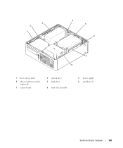
3 2 1 4 5 6 7 8 1 drive-release latch 4 chassis intrusion switch (optional) 7 system board 2 optical drive 5 hard drive 8 heat sink assembly 3 power supply 6 card slots (2) Small Form Factor Computer 189
3 2 1 4 5 6 7 8 1 drive-release latch 4 chassis intrusion switch (optional) 7 system board 2 optical drive 5 hard drive 8 heat sink assembly 3 power supply 6 card slots (2) Small Form Factor Computer 189
User's Guide
Page 190
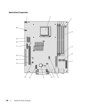
System Board Components 1 20 19 18 17 16 15 14 2 3 4 5 6 7 13 12 11 10 9 8 190 Small Form Factor Computer
System Board Components 1 20 19 18 17 16 15 14 2 3 4 5 6 7 13 12 11 10 9 8 190 Small Form Factor Computer

User's Guide
Page 192
192 Small Form Factor Computer
192 Small Form Factor Computer
User's Guide
Page 193
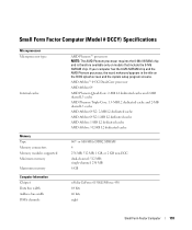
..., 1 GB, or 2 GB non-ECC dual-channel: 512 MB; single-channel: 256 MB 8 GB nVidia GeForce 6150LE/NForce 430 64 bits 40 bits eight Small Form Factor Computer 193 Small Form Factor Computer (Model # DCCY) Specifications Microprocessor Microprocessor type Internal cache Memory Type Memory connectors Memory modules supported Minimum memory Maximum memory Computer Information Chipset Data...
..., 1 GB, or 2 GB non-ECC dual-channel: 512 MB; single-channel: 256 MB 8 GB nVidia GeForce 6150LE/NForce 430 64 bits 40 bits eight Small Form Factor Computer 193 Small Form Factor Computer (Model # DCCY) Specifications Microprocessor Microprocessor type Internal cache Memory Type Memory connectors Memory modules supported Minimum memory Maximum memory Computer Information Chipset Data...


