Statement of Volatility
Page 2
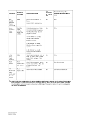
be SSD (solid state flash drive). Stores CMOS information. Hard drive(s) User Non Volatile magnetic media, Yes replaceable - Secondary power loss (removing the on-board coin-cell battery) destroys system data on the system configuration and time-of data) RTC CMOS - frame buffer ... Volatile memory, built in No PCH, for external data Remedial Action (Action necessary to prevent loss of -day information. 2012 Dell Inc. Description Reference Designator Volatility Description User Accessible for MAC address, LED mode, WOL settings, PXE settings. Volatile memory in GB.
be SSD (solid state flash drive). Stores CMOS information. Hard drive(s) User Non Volatile magnetic media, Yes replaceable - Secondary power loss (removing the on-board coin-cell battery) destroys system data on the system configuration and time-of data) RTC CMOS - frame buffer ... Volatile memory, built in No PCH, for external data Remedial Action (Action necessary to prevent loss of -day information. 2012 Dell Inc. Description Reference Designator Volatility Description User Accessible for MAC address, LED mode, WOL settings, PXE settings. Volatile memory in GB.
Owner's Manual
Page 3
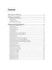
... the Wireless Wide Area Network (WWAN) Card (Optional 16 Removing the Optical Drive...16 Installing the Optical Drive...17 Removing the Primary Hard Drive...18 Installing the Primary Hard Drive...19 Removing the Secondary Hard Drive...19 Installing the Secondary Hard Drive...20 Removing the Coin-Cell Battery...20 Installing the Coin-Cell Battery...21 Removing the Processor Fan...21 Installing the Processor Fan...22...
... the Wireless Wide Area Network (WWAN) Card (Optional 16 Removing the Optical Drive...16 Installing the Optical Drive...17 Removing the Primary Hard Drive...18 Installing the Primary Hard Drive...19 Removing the Secondary Hard Drive...19 Installing the Secondary Hard Drive...20 Removing the Coin-Cell Battery...20 Installing the Coin-Cell Battery...21 Removing the Processor Fan...21 Installing the Processor Fan...22...
Owner's Manual
Page 18
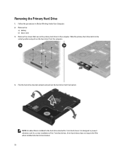
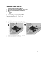
... for correct installation of the 7 mm hard drives. 9 mm hard drives does not require the filler when installed into hard-drive bracket. 18 Slide the primary hard drive latch to the computer. Follow the procedures in Before Working Inside Your Computer. 2. Remove the: a) battery b) base cover 3. Flex the hard-drive bracket outward and pull out the hard drive from the computer. 4. Removing the Primary Hard Drive 1.
... for correct installation of the 7 mm hard drives. 9 mm hard drives does not require the filler when installed into hard-drive bracket. 18 Slide the primary hard drive latch to the computer. Follow the procedures in Before Working Inside Your Computer. 2. Remove the: a) battery b) base cover 3. Flex the hard-drive bracket outward and pull out the hard drive from the computer. 4. Removing the Primary Hard Drive 1.
Owner's Manual
Page 19
.... 2. Follow the procedures in After Working Inside Your Computer. Install the: a) base cover b) battery 5. Removing the Secondary Hard Drive 1. Remove the screw that secure that secure secondary hard drive to the bracket. 6. Remove the screw that secondary hard drive in place. 3. Insert the primary hard drive into its slot in the computer till it clicks in place. 4. Tighten the screw to...
.... 2. Follow the procedures in After Working Inside Your Computer. Install the: a) base cover b) battery 5. Removing the Secondary Hard Drive 1. Remove the screw that secure that secure secondary hard drive to the bracket. 6. Remove the screw that secondary hard drive in place. 3. Insert the primary hard drive into its slot in the computer till it clicks in place. 4. Tighten the screw to...
Owner's Manual
Page 20
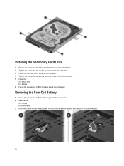
Install the: a) base cover b) battery 6. Install the secondary hard drive into the computer. 4. Tighten the screw that secure the secondary hard drive bracket. 3. Removing the Coin-Cell Battery 1. Remove the: a) battery b) base cover 3. Pry the coin-cell battery upward and remove it from the computer. 20 Follow the procedures in After Working Inside Your Computer. Follow the procedures...
Install the: a) base cover b) battery 6. Install the secondary hard drive into the computer. 4. Tighten the screw that secure the secondary hard drive bracket. 3. Removing the Coin-Cell Battery 1. Remove the: a) battery b) base cover 3. Pry the coin-cell battery upward and remove it from the computer. 20 Follow the procedures in After Working Inside Your Computer. Follow the procedures...
Owner's Manual
Page 34
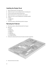
... to secure the display brackets to the palmrest. 4. Install the: a) display bezel b) battery 7. Removing the Palmrest 1. Tighten the screws to secure the display panel to the display panel. 2. Remove the: a) battery b) base cover c) keyboard trim d) keyboard e) optical drive f) primary hard drive g) secondary hard drive 3. Align the display brackets to the display assembly. 6. Disconnect the smart card cable...
... to secure the display brackets to the palmrest. 4. Install the: a) display bezel b) battery 7. Removing the Palmrest 1. Tighten the screws to secure the display panel to the display panel. 2. Remove the: a) battery b) base cover c) keyboard trim d) keyboard e) optical drive f) primary hard drive g) secondary hard drive 3. Align the display brackets to the display assembly. 6. Disconnect the smart card cable...
Owner's Manual
Page 39
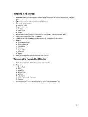
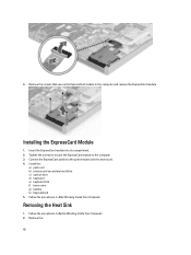
... the computer. 6. Follow the procedures in place. 2. Follow the procedures in Before Working Inside Your Computer. 2. Remove the: a) ExpressCard b) battery c) base cover d) keyboard trim e) keyboard f) optical drive g) primary and secondary hard drive h) palm rest 3. Installing the Palmrest 1. Removing the ExpressCard Module 1. Connect the smart card cable and affix the adhesive tape that secures the media...
... the computer. 6. Follow the procedures in place. 2. Follow the procedures in Before Working Inside Your Computer. 2. Remove the: a) ExpressCard b) battery c) base cover d) keyboard trim e) keyboard f) optical drive g) primary and secondary hard drive h) palm rest 3. Installing the Palmrest 1. Removing the ExpressCard Module 1. Connect the smart card cable and affix the adhesive tape that secures the media...
Owner's Manual
Page 40
... 3. Follow the procedures in After Working Inside Your Computer. 4. Follow the procedures in Before Working Inside Your Computer. 2. Install the: a) palm rest b) primary and secondary hard drive c) optical drive d) keyboard e) keyboard trim f) base cover g) battery h) ExpressCard 5. Removing the Heat Sink 1.
... 3. Follow the procedures in After Working Inside Your Computer. 4. Follow the procedures in Before Working Inside Your Computer. 2. Install the: a) palm rest b) primary and secondary hard drive c) optical drive d) keyboard e) keyboard trim f) base cover g) battery h) ExpressCard 5. Removing the Heat Sink 1.
Owner's Manual
Page 41
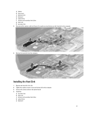
Replace the heat sink in its slot. 2. Connect the camera cable to the computer. 3. Remove the heat sink from the computer. Installing the Heat Sink 1. Install the: a) processor fan b) palm rest c) primary and secondary hard drive d) optical drive e) keyboard 41 Tighten the captive screws to secure the heat sink to the system board. 4. a) battery b) base cover c) keyboard trim d) keyboard e) optical drive f) primary and secondary hard drive g) palm rest h) processor fan 3. Disconnect the camera cable and loosen the captive screws that secure the heat sink to the computer. 4.
Replace the heat sink in its slot. 2. Connect the camera cable to the computer. 3. Remove the heat sink from the computer. Installing the Heat Sink 1. Install the: a) processor fan b) palm rest c) primary and secondary hard drive d) optical drive e) keyboard 41 Tighten the captive screws to secure the heat sink to the system board. 4. a) battery b) base cover c) keyboard trim d) keyboard e) optical drive f) primary and secondary hard drive g) palm rest h) processor fan 3. Disconnect the camera cable and loosen the captive screws that secure the heat sink to the computer. 4.
Owner's Manual
Page 42
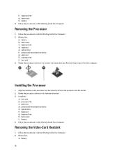
... processor into the socket. 2. Install the: a) heat sink b) processor fan c) palm rest d) primary and secondary hard drive e) optical drive f) keyboard g) keyboard trim h) base cover i) battery 4. Remove the: a) battery 42 Installing the Processor 1. Removing the Processor 1. Removing the Video-Card Heatsink 1. Remove the processor from the computer. Follow the procedures in Before Working Inside Your Computer. 2. Follow the...
... processor into the socket. 2. Install the: a) heat sink b) processor fan c) palm rest d) primary and secondary hard drive e) optical drive f) keyboard g) keyboard trim h) base cover i) battery 4. Remove the: a) battery 42 Installing the Processor 1. Removing the Processor 1. Removing the Video-Card Heatsink 1. Remove the processor from the computer. Follow the procedures in Before Working Inside Your Computer. 2. Follow the...
Owner's Manual
Page 43
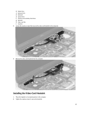
Place the heatsink on its original position in the computer. 2. Installing the Video-Card Heatsink 1. Loosen the captive screws that secures the video-card heatsink to secure the heatsink. 43 Tighten the captive screws to the computer. 4. b) bottom door c) keyboard trim d) keyboard e) optical drive f) primary and secondary hard drive g) palmrest h) video-card fan i) heatsink 3. Remove the video-card heatsink from the computer.
Place the heatsink on its original position in the computer. 2. Installing the Video-Card Heatsink 1. Loosen the captive screws that secures the video-card heatsink to secure the heatsink. 43 Tighten the captive screws to the computer. 4. b) bottom door c) keyboard trim d) keyboard e) optical drive f) primary and secondary hard drive g) palmrest h) video-card fan i) heatsink 3. Remove the video-card heatsink from the computer.
Owner's Manual
Page 44
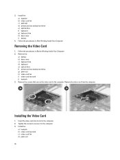
...: a) heatsink b) video-card heat sink c) video-card fan d) palm rest 44 Install the: a) heatsink b) video-card fan c) palmrest d) primary and secondary hard drive e) optical drive f) keyboard g) keyboard trim h) base cover i) battery 4. Remove the screws that secure the video card to the computer. 3. Tighten the screws to secure it to the computer. Insert the video...
...: a) heatsink b) video-card heat sink c) video-card fan d) palm rest 44 Install the: a) heatsink b) video-card fan c) palmrest d) primary and secondary hard drive e) optical drive f) keyboard g) keyboard trim h) base cover i) battery 4. Remove the screws that secure the video card to the computer. 3. Tighten the screws to secure it to the computer. Insert the video...
Owner's Manual
Page 45
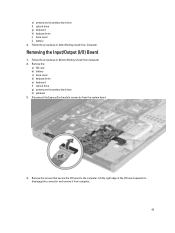
... Inside Your Computer. 2. Disconnect the ExpressCard module connector from computer. 45 Removing the Input/Output (I /O board to disengage the connector and remove it from the system board. 4. Remove the: a) SD card b) battery c) base cover d) keyboard trim e) keyboard f) optical drive g) primary and secondary hard drive h) palmrest 3. Remove the screws that secure the I /O) Board 1. Follow the procedures in After...
... Inside Your Computer. 2. Disconnect the ExpressCard module connector from computer. 45 Removing the Input/Output (I /O board to disengage the connector and remove it from the system board. 4. Remove the: a) SD card b) battery c) base cover d) keyboard trim e) keyboard f) optical drive g) primary and secondary hard drive h) palmrest 3. Remove the screws that secure the I /O) Board 1. Follow the procedures in After...
Owner's Manual
Page 46
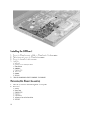
.... Connect the ExpressCard module connector. 4. Install the: a) palmrest b) primary and secondary hard drive c) optical drive d) keyboard e) keyboard trim f) base cover g) battery h) SD card 5. Connect the I/O board connector and slide the I /O board to the computer. 3. Remove the: a) battery b) base cover c) keyboard trim d) keyboard e) optical drive f) primary and secondary hard drive g) palmrest 46 Removing the Display Assembly 1. Installing the I/O Board 1.
.... Connect the ExpressCard module connector. 4. Install the: a) palmrest b) primary and secondary hard drive c) optical drive d) keyboard e) keyboard trim f) base cover g) battery h) SD card 5. Connect the I/O board connector and slide the I /O board to the computer. 3. Remove the: a) battery b) base cover c) keyboard trim d) keyboard e) optical drive f) primary and secondary hard drive g) palmrest 46 Removing the Display Assembly 1. Installing the I/O Board 1.
Owner's Manual
Page 49
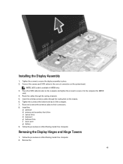
... Working Inside Your Computer. Insert the wireless antenna cables through the routing channels. 5. Follow the procedures in M6700 only. 3. Remove the: 49 Connect the camera and LVDS cables to their connectors. 8. Follow the procedures in place. 2.... Route the cables through the routing hole on the computer and tighten the screws to secure it to secure the display assembly in After Working Inside Your Computer. 2. Install the: a) palmrest b) primary and secondary hard drive...
... Working Inside Your Computer. Insert the wireless antenna cables through the routing channels. 5. Follow the procedures in M6700 only. 3. Remove the: 49 Connect the camera and LVDS cables to their connectors. 8. Follow the procedures in place. 2.... Route the cables through the routing hole on the computer and tighten the screws to secure it to secure the display assembly in After Working Inside Your Computer. 2. Install the: a) palmrest b) primary and secondary hard drive...
Owner's Manual
Page 50
... assembly c) palmrest d) primary and secondary hard drive e) optical drive f) keyboard g) keyboard trim h) base cover i) battery 5. Repeat steps 1 and 2 to the computer. 4. Remove the: a) battery b) base cover c) keyboard trim d) keyboard e) optical drive f) primary and secondary hard drive g) display assembly 3. Slide the right display...tower. a) battery b) base cover c) keyboard trim d) keyboard e) optical drive f) primary and secondary hard drive g) palmrest h) display assembly i) display bezel 3. Remove the left display hinge and the left display hinge to secure the left hinge...
... assembly c) palmrest d) primary and secondary hard drive e) optical drive f) keyboard g) keyboard trim h) base cover i) battery 5. Repeat steps 1 and 2 to the computer. 4. Remove the: a) battery b) base cover c) keyboard trim d) keyboard e) optical drive f) primary and secondary hard drive g) display assembly 3. Slide the right display...tower. a) battery b) base cover c) keyboard trim d) keyboard e) optical drive f) primary and secondary hard drive g) palmrest h) display assembly i) display bezel 3. Remove the left display hinge and the left display hinge to secure the left hinge...
Owner's Manual
Page 51
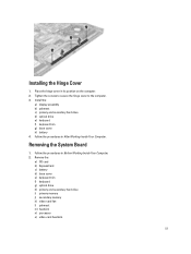
Tighten the screws to secure the hinge cover to the computer. 3. Removing the System Board 1. Remove the: a) SD card b) ExpressCard c) battery d) base cover e) keyboard trim f) keyboard g) optical drive h) primary and secondary hard drive i) primary memory j) secondary memory k) video-card fan l) palmrest m) heatsink n) processor o) video-card heatsink. 51 Installing the Hinge Cover 1. Follow the procedures in its...
Tighten the screws to secure the hinge cover to the computer. 3. Removing the System Board 1. Remove the: a) SD card b) ExpressCard c) battery d) base cover e) keyboard trim f) keyboard g) optical drive h) primary and secondary hard drive i) primary memory j) secondary memory k) video-card fan l) palmrest m) heatsink n) processor o) video-card heatsink. 51 Installing the Hinge Cover 1. Follow the procedures in its...
Owner's Manual
Page 55
... on the computer and tighten the screw to secure it to the computer. 6. Install all the mini-cards (if available). 5. Remove the: a) battery b) base cover c) keyboard trim d) keyboard e) optical drive f) primary and secondary hard drive g) palmrest h) I /O board b) video card c) video-card heat sink. a) switch board b) power connector c) LVDS d) camera e) coin-cell battery f) processor fan...
... on the computer and tighten the screw to secure it to the computer. 6. Install all the mini-cards (if available). 5. Remove the: a) battery b) base cover c) keyboard trim d) keyboard e) optical drive f) primary and secondary hard drive g) palmrest h) I /O board b) video card c) video-card heat sink. a) switch board b) power connector c) LVDS d) camera e) coin-cell battery f) processor fan...
Owner's Manual
Page 56
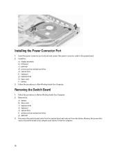
... c) palmrest d) primary and secondary hard drive e) optical drive f) keyboard g) keyboard trim h) base cover i) battery 3. Disconnect the switch-board cable from the system board and remove it from the latches. Follow the procedures in Before Working Inside Your Computer. 2. Removing the Switch Board 1. Follow the ... and connect the power-connector cable to the computer and remove it from the computer. 56 Remove the: a) battery b) base cover c) keyboard trim d) keyboard e) optical drive f) primary and secondary hard drive g) palmrest 3. Installing the Power Connector Port 1.
... c) palmrest d) primary and secondary hard drive e) optical drive f) keyboard g) keyboard trim h) base cover i) battery 3. Disconnect the switch-board cable from the system board and remove it from the latches. Follow the procedures in Before Working Inside Your Computer. 2. Removing the Switch Board 1. Follow the ... and connect the power-connector cable to the computer and remove it from the computer. 56 Remove the: a) battery b) base cover c) keyboard trim d) keyboard e) optical drive f) primary and secondary hard drive g) palmrest 3. Installing the Power Connector Port 1.
Owner's Manual
Page 59
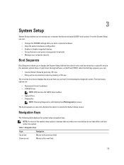
... specify BIOS‐level options. During the Power-on Self Test (POST), when the Dell logo appears, you can: • Access System Setup by pressing key • Bring... the devices that you make are : • Removable Drive (if available) • STXXXX Drive NOTE: XXX denotes the SATA drive number. • Optical Drive • Diagnostics NOTE: Choosing Diagnostics, will display ...Navigation Keys Keys Navigation Up arrow Moves to a specific device (for example: optical drive or hard drive). 3 System Setup System Setup enables you to manage your computer security Boot Sequence ...
... specify BIOS‐level options. During the Power-on Self Test (POST), when the Dell logo appears, you can: • Access System Setup by pressing key • Bring... the devices that you make are : • Removable Drive (if available) • STXXXX Drive NOTE: XXX denotes the SATA drive number. • Optical Drive • Diagnostics NOTE: Choosing Diagnostics, will display ...Navigation Keys Keys Navigation Up arrow Moves to a specific device (for example: optical drive or hard drive). 3 System Setup System Setup enables you to manage your computer security Boot Sequence ...


