
Service Manual
Page 3
Contents Chapter 1 System Overview 1-1 System Features 1-1 Physical Description 1-2 Indicator Panel 1-3 Power/Suspend Indicator 1-4 Diskette-Drive Access Indicator 1-4 Hard-Disk/CD-ROM Drive Access Indicator 1-4 PC Card Access Indicator 1-4 Low-Battery Indicator 1-4 Charging Indicator 1-4 Keyboard Indicators 1-5 Controlling Computer Power 1-5 Power States 1-5 Interrupt Assignments 1-6 Technical Specifications 1-7 Chapter 2 Initial ...
Contents Chapter 1 System Overview 1-1 System Features 1-1 Physical Description 1-2 Indicator Panel 1-3 Power/Suspend Indicator 1-4 Diskette-Drive Access Indicator 1-4 Hard-Disk/CD-ROM Drive Access Indicator 1-4 PC Card Access Indicator 1-4 Low-Battery Indicator 1-4 Charging Indicator 1-4 Keyboard Indicators 1-5 Controlling Computer Power 1-5 Power States 1-5 Interrupt Assignments 1-6 Technical Specifications 1-7 Chapter 2 Initial ...
Service Manual
Page 4
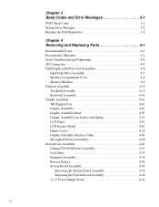
Chapter 3 Beep Codes and Error Messages 3-1 POST Beep Codes 3-1 System Error Messages 3-3 Running the Dell Diagnostics 3-8 Chapter 4 Removing and Replacing Parts 4-1 Recommended Tools 4-2 Precautionary Measures 4-2 Screw Identification and Tightening 4-4 ZIF Connectors 4-5 Field-...LCD Inverter Board 4-24 Hinge Covers 4-25 Display-Assembly Interface Cable 4-26 Microphone/Switch Assembly 4-28 Bottom Case Assembly 4-29 Diskette/CD-ROM Drive Assembly 4-31 Deck Buoy 4-33 Superpart Assembly 4-34 Reserve Battery 4-36 System Board Assembly 4-38 Removing the System Board Assembly ...
Chapter 3 Beep Codes and Error Messages 3-1 POST Beep Codes 3-1 System Error Messages 3-3 Running the Dell Diagnostics 3-8 Chapter 4 Removing and Replacing Parts 4-1 Recommended Tools 4-2 Precautionary Measures 4-2 Screw Identification and Tightening 4-4 ZIF Connectors 4-5 Field-...LCD Inverter Board 4-24 Hinge Covers 4-25 Display-Assembly Interface Cable 4-26 Microphone/Switch Assembly 4-28 Bottom Case Assembly 4-29 Diskette/CD-ROM Drive Assembly 4-31 Deck Buoy 4-33 Superpart Assembly 4-34 Reserve Battery 4-36 System Board Assembly 4-38 Removing the System Board Assembly ...

Service Manual
Page 5
...Repair Parts A-1 Recommended Tools A-1 Precautionary Measures A-1 Factory Repair Parts and Assemblies A-1 Exploded Views of Components and Assemblies A-12 Hard-Disk Drive A-15 CD-ROM Drive A-16 Diskette Drive A-16 Palmrest Assembly Components A-16 Trackball A-16 Trackball Interface Cable A-16 Trackball Button Board A-16 Palmrest Brace A-16 Display ...25 Power Button and Power-Button Mounting Bracket A-26 Spreader and Keel Plates A-27 Appendix B System Setup Options B-1 Accessing the Dell Control Center B-1 Accessing the System Setup Program B-2 System Setup Screens B-3 vii
...Repair Parts A-1 Recommended Tools A-1 Precautionary Measures A-1 Factory Repair Parts and Assemblies A-1 Exploded Views of Components and Assemblies A-12 Hard-Disk Drive A-15 CD-ROM Drive A-16 Diskette Drive A-16 Palmrest Assembly Components A-16 Trackball A-16 Trackball Interface Cable A-16 Trackball Button Board A-16 Palmrest Brace A-16 Display ...25 Power Button and Power-Button Mounting Bracket A-26 Spreader and Keel Plates A-27 Appendix B System Setup Options B-1 Accessing the Dell Control Center B-1 Accessing the System Setup Program B-2 System Setup Screens B-3 vii

Service Manual
Page 6
... Assembly Removal 4-18 Figure 4-15. Index Figures Figure 1-1. Computer Orientation 4-1 Figure 4-2. Palmrest Assembly Removal 4-10 Figure 4-10. LCD Inverter Board Removal 4-24 Figure 4-19. Diskette/CD-ROM Drive Assembly Removal 4-31 Figure 4-24. Advanced Port Replicator Connector Dust Cover 4-43 Figure 4-32. Screw Identification 4-4 Figure 4-4. Hard-Disk Drive Assembly Removal 4-7 Figure 4-7. Palmrest...
... Assembly Removal 4-18 Figure 4-15. Index Figures Figure 1-1. Computer Orientation 4-1 Figure 4-2. Palmrest Assembly Removal 4-10 Figure 4-10. LCD Inverter Board Removal 4-24 Figure 4-19. Diskette/CD-ROM Drive Assembly Removal 4-31 Figure 4-24. Advanced Port Replicator Connector Dust Cover 4-43 Figure 4-32. Screw Identification 4-4 Figure 4-4. Hard-Disk Drive Assembly Removal 4-7 Figure 4-7. Palmrest...

Service Manual
Page 9
... 8- The computer supports type I, type II, or type III cards (in CD-ROM drive - For a complete list of system features, see "Technical Specifications" found in a Dell portable computer, the Dell Latitude XPi CD models include the following standard features: - and 16-MB fast-page memory modules...this chapter. ory. MPEG software - System Overview 1-1 SoundBlasterPro-compatible voice and music functions - Chapter 1 System Overview The Dell® Latitude® XPi CD is attached to the PCI bus. • Full multimedia capability through the following new features: • 64-bit-wide ...
... 8- The computer supports type I, type II, or type III cards (in CD-ROM drive - For a complete list of system features, see "Technical Specifications" found in a Dell portable computer, the Dell Latitude XPi CD models include the following standard features: - and 16-MB fast-page memory modules...this chapter. ory. MPEG software - System Overview 1-1 SoundBlasterPro-compatible voice and music functions - Chapter 1 System Overview The Dell® Latitude® XPi CD is attached to the PCI bus. • Full multimedia capability through the following new features: • 64-bit-wide ...

Service Manual
Page 10
Physical Description display assembly LCD panel keyboard trackball assembly display assembly latch indicator panel microphone tilt-support foot (2) infrared port diskette drive main battery assembly speaker bottom case assembly CD-ROM drive Figure 1-1. Front View of the Notebook Computer 1-2 Dell Latitude XPi CD Service Manual
Physical Description display assembly LCD panel keyboard trackball assembly display assembly latch indicator panel microphone tilt-support foot (2) infrared port diskette drive main battery assembly speaker bottom case assembly CD-ROM drive Figure 1-1. Front View of the Notebook Computer 1-2 Dell Latitude XPi CD Service Manual
Service Manual
Page 11
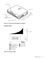
indicator panel hard-disk drive I/O panel infrared port Advanced Port Replicator connector DC power input connector security cable slot audio jacks (3) speaker PC Card slot power switch tilt-support foot Figure 1-2. Indicator Panel Num Lock indicator Caps Lock indicator Scroll Lock indicator System Overview 1-3 Back View of the Notebook Computer Indicator Panel LCD panel Legend power/suspend indicator diskette-drive access indicator hard-disk/CD-ROM drive access indicator PC Card access indicator low-battery indicator charging indicator Figure 1-3.
indicator panel hard-disk drive I/O panel infrared port Advanced Port Replicator connector DC power input connector security cable slot audio jacks (3) speaker PC Card slot power switch tilt-support foot Figure 1-2. Indicator Panel Num Lock indicator Caps Lock indicator Scroll Lock indicator System Overview 1-3 Back View of the Notebook Computer Indicator Panel LCD panel Legend power/suspend indicator diskette-drive access indicator hard-disk/CD-ROM drive access indicator PC Card access indicator low-battery indicator charging indicator Figure 1-3.

Service Manual
Page 12
... is an amber LED. The indicator lights when data is an amber LED. The indicator lights when data is fully charged. 1-4 Dell Latitude XPi CD Service Manual The low-battery indicator turns on the keyboard assembly. The indicator turns on , the power/suspend indicator lights up constantly ...is a green LED. The subsections that the computer is fully closed. This indicator is a green LED. Hard-Disk/CD-ROM Drive Access Indicator The hard-disk/CD-ROM drive access indicator is used in conjunction with the speaker to indicate either of the following low-battery conditions: •...
... is an amber LED. The indicator lights when data is an amber LED. The indicator lights when data is fully charged. 1-4 Dell Latitude XPi CD Service Manual The low-battery indicator turns on the keyboard assembly. The indicator turns on , the power/suspend indicator lights up constantly ...is a green LED. The subsections that the computer is fully closed. This indicator is a green LED. Hard-Disk/CD-ROM Drive Access Indicator The hard-disk/CD-ROM drive access indicator is used in conjunction with the speaker to indicate either of the following low-battery conditions: •...

Service Manual
Page 14
... in suspend-to-disk mode, sliding the power button causes the computer to indicate that the output buffer of the microprocessor IRQ15 Reserved for the CD-ROM drive 1-6 Dell Latitude XPi CD Service Manual The computer remains in suspend mode (the power/suspend indicator flashes every 8 seconds), if the display is closed, and if no external...
... in suspend-to-disk mode, sliding the power button causes the computer to indicate that the output buffer of the microprocessor IRQ15 Reserved for the CD-ROM drive 1-6 Dell Latitude XPi CD Service Manual The computer remains in suspend mode (the power/suspend indicator flashes every 8 seconds), if the display is closed, and if no external...
Service Manual
Page 18
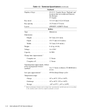
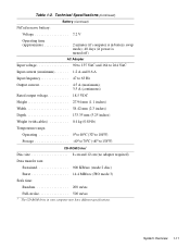
....4 VDC Capacity 36 WH Charge time (approximate):2 Computer on 2.5 hours Computer off 1.5 hours Operating time (approximate, with no power management features enabled)2 2 to 3.5 hours (without a CD-ROM drive in use) Life span (approximate)2 400 discharge/charge cycles Temperature range: Charge 10° to 40°C (50° to 104°F) Discharge 10... features such as charge time, operating time, and life span can vary according to the conditions under which the computer and battery are used. 1-10 Dell Latitude XPi CD Service Manual Table 1-2.
....4 VDC Capacity 36 WH Charge time (approximate):2 Computer on 2.5 hours Computer off 1.5 hours Operating time (approximate, with no power management features enabled)2 2 to 3.5 hours (without a CD-ROM drive in use) Life span (approximate)2 400 discharge/charge cycles Temperature range: Charge 10° to 40°C (50° to 104°F) Discharge 10... features such as charge time, operating time, and life span can vary according to the conditions under which the computer and battery are used. 1-10 Dell Latitude XPi CD Service Manual Table 1-2.
Service Manual
Page 19
... (0.89 lb) Temperature range: Operating 0° to 40°C (32° to 104°F) Storage 40° to 70°C (-40° to 158°F) CD-ROM Drive3 Disc size 8 cm and 12 cm (no adapter required) Data transfer rate: Sustained 900 KB/sec (mode 2 disc) Burst 14.4 MB/sec (PIO mode...
... (0.89 lb) Temperature range: Operating 0° to 40°C (32° to 104°F) Storage 40° to 70°C (-40° to 158°F) CD-ROM Drive3 Disc size 8 cm and 12 cm (no adapter required) Data transfer rate: Sustained 900 KB/sec (mode 2 disc) Burst 14.4 MB/sec (PIO mode...

Service Manual
Page 20
Technical Specifications (Continued) CD-ROM Drive3 (Continued) Access time: Random 250 m/sec Full-stroke 550 m/sec Memory buffer 128 KB Physical (Computer) Height 63.0 mm (2.48 inches) Width 280.9 mm (...) Maximum vibration: Operating 0.51 GRMS, using a random-vibration spectrum that simulates truck shipment Storage 1.1 GRMS, using a random-vibration spectrum that simulates air/truck shipment 3 The CD-ROM drive in your computer may have different specifications. 1-12 Dell Latitude XPi CD Service Manual Table 1-2.
Technical Specifications (Continued) CD-ROM Drive3 (Continued) Access time: Random 250 m/sec Full-stroke 550 m/sec Memory buffer 128 KB Physical (Computer) Height 63.0 mm (2.48 inches) Width 280.9 mm (...) Maximum vibration: Operating 0.51 GRMS, using a random-vibration spectrum that simulates truck shipment Storage 1.1 GRMS, using a random-vibration spectrum that simulates air/truck shipment 3 The CD-ROM drive in your computer may have different specifications. 1-12 Dell Latitude XPi CD Service Manual Table 1-2.
Service Manual
Page 33
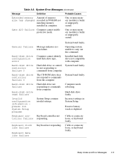
... responding to commands from computer. System board faulty. Cable or connector loose, or keyboard faulty. One or more memory module(s) faulty or improperly seated. The CD-ROM drive does not respond to carry out the command. System Setup contains invalid settings. Reserve battery weak or depleted. System board faulty. Computer needs rebooting...
... responding to commands from computer. System board faulty. Cable or connector loose, or keyboard faulty. One or more memory module(s) faulty or improperly seated. The CD-ROM drive does not respond to carry out the command. System Setup contains invalid settings. Reserve battery weak or depleted. System board faulty. Computer needs rebooting...

Service Manual
Page 36
... is critically low. Running the Dell Diagnostics The diagnostics contains tests that aid in RTC does not match system clock. Tests the video subsystem • Keyboard - Tests the IDE hard-disk drive subsystem • IDE CD-ROM Drives - Main battery needs recharging...System clock stopped. System board faulty. The diagnostics diskette contains the following test groups: • RAM - Tests the CD-ROM drive subsystem 3-8 Dell Latitude XPi CD Service Manual Table 3-2. Defective diskette or hard-disk drive. Reserve battery lost its charge. Tests the keyboard subsystem •...
... is critically low. Running the Dell Diagnostics The diagnostics contains tests that aid in RTC does not match system clock. Tests the video subsystem • Keyboard - Tests the IDE hard-disk drive subsystem • IDE CD-ROM Drives - Main battery needs recharging...System clock stopped. System board faulty. The diagnostics diskette contains the following test groups: • RAM - Tests the CD-ROM drive subsystem 3-8 Dell Latitude XPi CD Service Manual Table 3-2. Defective diskette or hard-disk drive. Reserve battery lost its charge. Tests the keyboard subsystem •...
Service Manual
Page 44
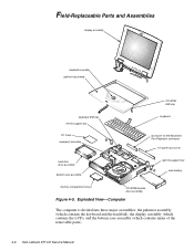
Field-Replaceable Parts and Assemblies display assembly trackball assembly palmrest assembly CD-ROM EMI clip keyboard EMI clip left tilt-support foot keyboard PC Card superpart assembly dust cover for the Advanced Port Replicator connector...cover CD-ROM/diskette drive assembly Figure 4-5. Exploded View-Computer The computer is divided into three major assemblies: the palmrest assembly (which contains the keyboard and the trackball), the display assembly (which contains the LCD), and the bottom case assembly (which contains many of the removable parts). 4-6 Dell Latitude XPi CD Service ...
Field-Replaceable Parts and Assemblies display assembly trackball assembly palmrest assembly CD-ROM EMI clip keyboard EMI clip left tilt-support foot keyboard PC Card superpart assembly dust cover for the Advanced Port Replicator connector...cover CD-ROM/diskette drive assembly Figure 4-5. Exploded View-Computer The computer is divided into three major assemblies: the palmrest assembly (which contains the keyboard and the trackball), the display assembly (which contains the LCD), and the bottom case assembly (which contains many of the removable parts). 4-6 Dell Latitude XPi CD Service ...
Service Manual
Page 48
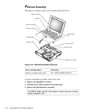
Remove any cables attached to prevent scratching the computer cover. 4-10 Dell Latitude XPi CD Service Manual Palmrest Assembly The palmrest assembly consists of the trackball and the keyboard. Palmrest Assembly Removal bottom case assembly Part or Assembly Name Palmrest ... PC Card(s). 2. CAUTION: Make sure the work surface is clean to the audio ports. 3. display assembly keyboard palmrest assembly trackball assembly trackball cable connector JTB CD-ROM EMI clip connector JKB1 connector JKB2 Figure 4-9. Remove the hard-disk drive assembly.
Remove any cables attached to prevent scratching the computer cover. 4-10 Dell Latitude XPi CD Service Manual Palmrest Assembly The palmrest assembly consists of the trackball and the keyboard. Palmrest Assembly Removal bottom case assembly Part or Assembly Name Palmrest ... PC Card(s). 2. CAUTION: Make sure the work surface is clean to the audio ports. 3. display assembly keyboard palmrest assembly trackball assembly trackball cable connector JTB CD-ROM EMI clip connector JKB1 connector JKB2 Figure 4-9. Remove the hard-disk drive assembly.

Service Manual
Page 50
...is properly aligned and fully seated on the bottom case assembly and that the palmrest assembly is free from the bottom case assembly. 4-12 Dell Latitude XPi CD Service Manual Set the palmrest assembly top side down on all of the mounting tabs are fully engaged. Ensure that all sides of the... turn the computer upside down , slightly forward of its original position, on top of the computer. CAUTION: Be careful not to bend the CD-ROM EMI clip. To reseat the palmrest assembly on the bottom case assembly, set the palmrest assembly down on the work surface, and reinstall retaining screws...
...is properly aligned and fully seated on the bottom case assembly and that the palmrest assembly is free from the bottom case assembly. 4-12 Dell Latitude XPi CD Service Manual Set the palmrest assembly top side down on all of the mounting tabs are fully engaged. Ensure that all sides of the... turn the computer upside down , slightly forward of its original position, on top of the computer. CAUTION: Be careful not to bend the CD-ROM EMI clip. To reseat the palmrest assembly on the bottom case assembly, set the palmrest assembly down on the work surface, and reinstall retaining screws...

Service Manual
Page 67
Bottom Case Assembly The bottom case assembly consists of the following: • Diskette/CD-ROM assembly • Deck-buoy • Superpart assembly • System board • 3.1-V power supply board • I/O-panel dust cover • Dust cover for the Advanced Port Replicator • Audio board Removing and Replacing Parts 4-29
Bottom Case Assembly The bottom case assembly consists of the following: • Diskette/CD-ROM assembly • Deck-buoy • Superpart assembly • System board • 3.1-V power supply board • I/O-panel dust cover • Dust cover for the Advanced Port Replicator • Audio board Removing and Replacing Parts 4-29

Service Manual
Page 69
...assembly Part or Assembly Name Diskette drive assembly CD-ROM drive assembly Order Name SVC,ASSY,FD,LXPiCD SVC,ASSY,CDROM,LXPiCD To remove the diskette/CD-ROM drive assembly, follow these steps: 1. Diskette/CD-ROM Drive Assembly connector JCDROM connector JFLOP CD-ROM flex cable D3 (2 mm) D9 (2 ...mm) D1 (4 mm) D4 (2 mm) plastic flip lock CD-ROM drive diskette drive D2 (4 mm) 4 mm bracket...
...assembly Part or Assembly Name Diskette drive assembly CD-ROM drive assembly Order Name SVC,ASSY,FD,LXPiCD SVC,ASSY,CDROM,LXPiCD To remove the diskette/CD-ROM drive assembly, follow these steps: 1. Diskette/CD-ROM Drive Assembly connector JCDROM connector JFLOP CD-ROM flex cable D3 (2 mm) D9 (2 ...mm) D1 (4 mm) D4 (2 mm) plastic flip lock CD-ROM drive diskette drive D2 (4 mm) 4 mm bracket...

Service Manual
Page 70
...replacing the drive assembly, first connect the two drive interface cables to the diskette drive. 4-32 Dell Latitude XPi CD Service Manual Then lower the drive assembly into a diskette drive and a CD-ROM drive, remove screws D3 through D9. Place the assembly on the bottom case assembly. Lift the..., release each connector's plastic flip lock (see Figure 4-23). Lift up about 1 inch. CAUTION: Use care when handling the diskette/CD-ROM drive; doing so can ruin the cable's electrical conductivity. 5. Lift the drive assembly out of the drive assembly engages tabs on a flat...
...replacing the drive assembly, first connect the two drive interface cables to the diskette drive. 4-32 Dell Latitude XPi CD Service Manual Then lower the drive assembly into a diskette drive and a CD-ROM drive, remove screws D3 through D9. Place the assembly on the bottom case assembly. Lift the..., release each connector's plastic flip lock (see Figure 4-23). Lift up about 1 inch. CAUTION: Use care when handling the diskette/CD-ROM drive; doing so can ruin the cable's electrical conductivity. 5. Lift the drive assembly out of the drive assembly engages tabs on a flat...


