Service Manual
Page 4
... and Error Messages 3-1 POST Beep Codes 3-1 System Error Messages 3-3 Running the Dell Diagnostics 3-8 Chapter 4 Removing and Replacing Parts 4-1 Recommended Tools 4-2 Precautionary Measures 4-2 Screw Identification and Tightening 4-4 ZIF Connectors 4-5 Field-Replaceable Parts and Assemblies 4-6 Hard-Disk Drive Assembly 4-7 Memory Compartment Cover 4-8 Memory Modules 4-9 Palmrest Assembly 4-10 Trackball Assembly 4-13 Keyboard Assembly 4-14 Display Assembly...
... and Error Messages 3-1 POST Beep Codes 3-1 System Error Messages 3-3 Running the Dell Diagnostics 3-8 Chapter 4 Removing and Replacing Parts 4-1 Recommended Tools 4-2 Precautionary Measures 4-2 Screw Identification and Tightening 4-4 ZIF Connectors 4-5 Field-Replaceable Parts and Assemblies 4-6 Hard-Disk Drive Assembly 4-7 Memory Compartment Cover 4-8 Memory Modules 4-9 Palmrest Assembly 4-10 Trackball Assembly 4-13 Keyboard Assembly 4-14 Display Assembly...

Service Manual
Page 6
Computer Orientation 4-1 Figure 4-2. Exploded View-Computer 4-6 Figure 4-6. Hard-Disk Drive Assembly Removal 4-7 Figure 4-7. Memory Compartment Cover Removal 4-8 Figure 4-8. Palmrest-Assembly Retaining Screws 4-11 Figure 4-11. Display Assembly Bezel Removal... Power Supply Board Removal 4-41 Figure 4-30. Front View of the Notebook Computer 1-3 Figure 1-3. Back View of the Notebook Computer 1-2 Figure 1-2. Memory Module Removal 4-9 Figure 4-9. Display Assembly Removal 4-18 Figure 4-15. Diskette/CD-ROM Drive Assembly Removal 4-31 Figure 4-24. Indicator Panel 1-3 Figure...
Computer Orientation 4-1 Figure 4-2. Exploded View-Computer 4-6 Figure 4-6. Hard-Disk Drive Assembly Removal 4-7 Figure 4-7. Memory Compartment Cover Removal 4-8 Figure 4-8. Palmrest-Assembly Retaining Screws 4-11 Figure 4-11. Display Assembly Bezel Removal... Power Supply Board Removal 4-41 Figure 4-30. Front View of the Notebook Computer 1-3 Figure 1-3. Back View of the Notebook Computer 1-2 Figure 1-2. Memory Module Removal 4-9 Figure 4-9. Display Assembly Removal 4-18 Figure 4-15. Diskette/CD-ROM Drive Assembly Removal 4-31 Figure 4-24. Indicator Panel 1-3 Figure...

Service Manual
Page 9
... a complete list of system features, see "Technical Specifications" found in this computer. MPEG software - Chapter 1 System Overview The Dell® Latitude® XPi CD is attached to the PCI bus. • Full multimedia capability through the following new features: • 64-bit-wide... of the Personal Computer Memory Card International Association (PCMCIA). System Features In addition to 48 MB by installing combinations of this chapter. Memory can be increased up to the standard features found later in a Dell portable computer, the Dell Latitude XPi CD models include the ...
... a complete list of system features, see "Technical Specifications" found in this computer. MPEG software - Chapter 1 System Overview The Dell® Latitude® XPi CD is attached to the PCI bus. • Full multimedia capability through the following new features: • 64-bit-wide... of the Personal Computer Memory Card International Association (PCMCIA). System Features In addition to 48 MB by installing combinations of this chapter. Memory can be increased up to the standard features found later in a Dell portable computer, the Dell Latitude XPi CD models include the ...

Service Manual
Page 15
...; Technical Specifications Microprocessor Microprocessor type Intel Pentium microprocessor Microprocessor speed 150 MHz Bus architecture PCI Internal cache memory 16 KB External cache memory 256 KB pipelined-burst SRAM Math coprocessor internal to the microprocessor Chip Set and Bus System chip set... cards) Cards supported 3.3-V and 5-V PC Card connector size 68 pins Data width (maximum 32 bits Memory Architecture EDO memory1 Memory module sockets two 1 The system supports fast-page-mode memory modules for memory upgrades. Technical Specifications Table 1-2. System Overview 1-7
...; Technical Specifications Microprocessor Microprocessor type Intel Pentium microprocessor Microprocessor speed 150 MHz Bus architecture PCI Internal cache memory 16 KB External cache memory 256 KB pipelined-burst SRAM Math coprocessor internal to the microprocessor Chip Set and Bus System chip set... cards) Cards supported 3.3-V and 5-V PC Card connector size 68 pins Data width (maximum 32 bits Memory Architecture EDO memory1 Memory module sockets two 1 The system supports fast-page-mode memory modules for memory upgrades. Technical Specifications Table 1-2. System Overview 1-7

Service Manual
Page 16
Table 1-2. and 16-MB fast-page mode Standard RAM 16 MB (EDO) on system board Maximum RAM 48 MB Memory access time: tRAC 70 ns tCAC 20 ns BIOS address F000:0000 Connectors Serial (DTE one 9-pin connector; 16550-compatible, ... 3D audio spatializer Stereo conversion 16 bit (analog-to-digital and digitalto-analog) FM music synthesizer 20-voice, 72-operator 1-8 Dell Latitude XPi CD Service Manual Technical Specifications (Continued) Memory (Continued) Memory module type and capacities 8- unidirectional, bidirectional, EPP 1.9, or ECP Monitor one 15-hole connector PS/2 one 6-pin mini-DIN...
Table 1-2. and 16-MB fast-page mode Standard RAM 16 MB (EDO) on system board Maximum RAM 48 MB Memory access time: tRAC 70 ns tCAC 20 ns BIOS address F000:0000 Connectors Serial (DTE one 9-pin connector; 16550-compatible, ... 3D audio spatializer Stereo conversion 16 bit (analog-to-digital and digitalto-analog) FM music synthesizer 20-voice, 72-operator 1-8 Dell Latitude XPi CD Service Manual Technical Specifications (Continued) Memory (Continued) Memory module type and capacities 8- unidirectional, bidirectional, EPP 1.9, or ECP Monitor one 15-hole connector PS/2 one 6-pin mini-DIN...

Service Manual
Page 17
... Controls volume can be controlled through key combinations, software application menus, or the Speaker window in the Dell Control Center Video Video type hardware-accelerated, 128-bit PCI Video controller NeoMagic 2090 Integrated video memory 1.1 MB Display Type active-matrix color (TFT) Dimensions: Height 195.0 mm (7.68 inches) Width...31 mm Power consumption: Panel (typical 0.69 W Backlight 2.10 W Controls brightness can be controlled through a key combination, the Display window in the Dell Control Center, or the System Setup program System Overview 1-9 Table 1-2.
... Controls volume can be controlled through key combinations, software application menus, or the Speaker window in the Dell Control Center Video Video type hardware-accelerated, 128-bit PCI Video controller NeoMagic 2090 Integrated video memory 1.1 MB Display Type active-matrix color (TFT) Dimensions: Height 195.0 mm (7.68 inches) Width...31 mm Power consumption: Panel (typical 0.69 W Backlight 2.10 W Controls brightness can be controlled through a key combination, the Display window in the Dell Control Center, or the System Setup program System Overview 1-9 Table 1-2.

Service Manual
Page 20
Table 1-2. Technical Specifications (Continued) CD-ROM Drive3 (Continued) Access time: Random 250 m/sec Full-stroke 550 m/sec Memory buffer 128 KB Physical (Computer) Height 63.0 mm (2.48 inches) Width 280.9 mm (11.06 inches) Depth 233.5 mm (9.19 inches) Weight (with battery and ... truck shipment Storage 1.1 GRMS, using a random-vibration spectrum that simulates air/truck shipment 3 The CD-ROM drive in your computer may have different specifications. 1-12 Dell Latitude XPi CD Service Manual
Table 1-2. Technical Specifications (Continued) CD-ROM Drive3 (Continued) Access time: Random 250 m/sec Full-stroke 550 m/sec Memory buffer 128 KB Physical (Computer) Height 63.0 mm (2.48 inches) Width 280.9 mm (11.06 inches) Depth 233.5 mm (9.19 inches) Weight (with battery and ... truck shipment Storage 1.1 GRMS, using a random-vibration spectrum that simulates air/truck shipment 3 The CD-ROM drive in your computer may have different specifications. 1-12 Dell Latitude XPi CD Service Manual

Service Manual
Page 25
... Open the display assembly, and verify that the trackball and its interface cable are free of any obvious damage, and then reinstall the memory modules. 9. mentation for the monitor. • The monitor and its associated switches operate freely. 12. face cable are secure enough to... monitor's controls are free of any obvious phys- nector on the I /O panel. • The mouse and its compartment. 6. For any memory modules from battery power, remove the main battery assembly, verify that secure the connectors at each end of any obvious physical damage, and then reinsert...
... Open the display assembly, and verify that the trackball and its interface cable are free of any obvious damage, and then reinstall the memory modules. 9. mentation for the monitor. • The monitor and its associated switches operate freely. 12. face cable are secure enough to... monitor's controls are free of any obvious phys- nector on the I /O panel. • The mouse and its compartment. 6. For any memory modules from battery power, remove the main battery assembly, verify that secure the connectors at each end of any obvious physical damage, and then reinsert...

Service Manual
Page 27
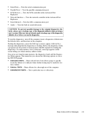
...it is assigned to the proper troubleshooting steps for the Diagnostics Menu. Insert another copy of the devices. See "Running the Dell Diagnostics" in Chapter 3. If you suspect that the same resource is possible that resource conflicts might exist, check the computer...," in disorderly or erratic computer operation or failure of the problem, call Dell for technical assistance. For more devices. See "Running the Dell Diagnostics" in Chapter 3. Yes. No. Proceed to step 6. 6. Because a device may require dedicated memory spaces, interrupt levels, or DMA channels, all .
...it is assigned to the proper troubleshooting steps for the Diagnostics Menu. Insert another copy of the devices. See "Running the Dell Diagnostics" in Chapter 3. If you suspect that the same resource is possible that resource conflicts might exist, check the computer...," in disorderly or erratic computer operation or failure of the problem, call Dell for technical assistance. For more devices. See "Running the Dell Diagnostics" in Chapter 3. Yes. No. Proceed to step 6. 6. Because a device may require dedicated memory spaces, interrupt levels, or DMA channels, all .

Service Manual
Page 29
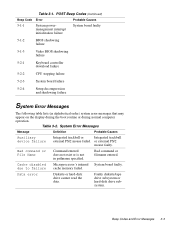
...Code Error Probable Causes 1-1-3 NVRAM write/read failure System board faulty 1-3-1 through 2-4-4 Installed memory module(s) not being properly identified or used Memory module improperly seated or system memory controller faulty (system board faulty) Beep Codes and Error Messages 3-1 system board failure faulty...corrupted; Table 3-1. The tables in each case. system board faulty 1-1-4 ROM BIOS checksum BIOS corrupted; See "Running the Dell Diagnostics" found later in the case of the problem. POST Beep Codes If the display cannot display error messages during the...
...Code Error Probable Causes 1-1-3 NVRAM write/read failure System board faulty 1-3-1 through 2-4-4 Installed memory module(s) not being properly identified or used Memory module improperly seated or system memory controller faulty (system board faulty) Beep Codes and Error Messages 3-1 system board failure faulty...corrupted; Table 3-1. The tables in each case. system board faulty 1-1-4 ROM BIOS checksum BIOS corrupted; See "Running the Dell Diagnostics" found later in the case of the problem. POST Beep Codes If the display cannot display error messages during the...

Service Manual
Page 30
...Master interrupt mask register failure System board faulty 3-1-4 3-2-4 3-3-4 Slave interrupt mask register failure Keyboard controller test failure Display memory test failure Keyboard assembly faulty or system board faulty System board faulty 3-4-1 Display initialization failure 3-4-2 4-2-1 Display retrace ...Math coprocessor failure Memory module improperly seated or system memory controller faulty (system board faulty) System board faulty Reserve battery faulty or system board faulty System board faulty System board faulty System board faulty 3-2 Dell Latitude XPi CD Service Manual
...Master interrupt mask register failure System board faulty 3-1-4 3-2-4 3-3-4 Slave interrupt mask register failure Keyboard controller test failure Display memory test failure Keyboard assembly faulty or system board faulty System board faulty 3-4-1 Display initialization failure 3-4-2 4-2-1 Display retrace ...Math coprocessor failure Memory module improperly seated or system memory controller faulty (system board faulty) System board faulty Reserve battery faulty or system board faulty System board faulty System board faulty System board faulty 3-2 Dell Latitude XPi CD Service Manual
Service Manual
Page 31
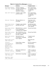
... or is not in alphabetical order) system error messages that may appear on the display during the boot routine or during normal computer operation. cache memory failed. Beep Codes and Error Messages 3-3 System Error Messages Message Definition Probable Causes Auxiliary device failure Integrated trackball or Integrated trackball external PS/2 mouse failed...
... or is not in alphabetical order) system error messages that may appear on the display during the boot routine or during normal computer operation. cache memory failed. Beep Codes and Error Messages 3-3 System Error Messages Message Definition Probable Causes Auxiliary device failure Integrated trackball or Integrated trackball external PS/2 mouse failed...

Service Manual
Page 32
...Diskette subsystem failed to respond to initialize. Table 3-2. System Error Messages (Continued) Message Definition Probable Causes Decreasing available memory Informational message indicating memory is writeprotected, operation cannot be missing from computer. Hard-disk drive data in the diskette drive. Diskette drive interface... or unformatted diskette. The diskette may be completed. Diskette is failing (usually preceded by memory error message). PC Card software faulty or incorrectly installed. 3-4 Dell Latitude XPi CD Service Manual Diskette drive faulty.
...Diskette subsystem failed to respond to initialize. Table 3-2. System Error Messages (Continued) Message Definition Probable Causes Decreasing available memory Informational message indicating memory is writeprotected, operation cannot be missing from computer. Hard-disk drive data in the diskette drive. Diskette drive interface... or unformatted diskette. The diskette may be completed. Diskette is failing (usually preceded by memory error message). PC Card software faulty or incorrectly installed. 3-4 Dell Latitude XPi CD Service Manual Diskette drive faulty.
Service Manual
Page 33
... keyboard faulty. Installed hard-disk drive not compatible with computer. System board faulty. Keyboard not responding. One or more memory module(s) faulty or improperly seated. Incorrect settings in computer. Keyboard controller not responding. Beep Codes and Error Messages 3-5... Hard-disk drive faulty. System Error Messages (Continued) Message Definition Probable Causes Extended memory Amount of memory size has changed recorded in NVRAM not matching memory installed in System Setup. General failure Hard-disk drive configuration error Hard-disk drive ...
... keyboard faulty. Installed hard-disk drive not compatible with computer. System board faulty. Keyboard not responding. One or more memory module(s) faulty or improperly seated. Incorrect settings in computer. Keyboard controller not responding. Beep Codes and Error Messages 3-5... Hard-disk drive faulty. System Error Messages (Continued) Message Definition Probable Causes Extended memory Amount of memory size has changed recorded in NVRAM not matching memory installed in System Setup. General failure Hard-disk drive configuration error Hard-disk drive ...

Service Manual
Page 34
... failure at address, read value expecting value Memory allocation error Memory control logic not operating properly. Faulty application program 3-6 Dell Latitude XPi CD Service Manual For external keyboard or keypad, cable or connector loose or keyboard faulty. Installed memory module faulty or improperly seated. For built-in use conflicts with the operating system, an application program...
... failure at address, read value expecting value Memory allocation error Memory control logic not operating properly. Faulty application program 3-6 Dell Latitude XPi CD Service Manual For external keyboard or keypad, cable or connector loose or keyboard faulty. Installed memory module faulty or improperly seated. For built-in use conflicts with the operating system, an application program...

Service Manual
Page 35
... boot diskette Unable to boot from which it is trying to locate a sector on harddisk drive or diskette. Table 3-2. Installed memory module faulty or improperly seated. Operating system boot files missing or corrupted. No timer tick interrupt Timer on harddisk drive. Optional ... system files on diskette or hard-disk drive. System Error Messages (Continued) Message Definition Probable Causes Memory data line failure at address, read value expecting value Memory not operating properly. System board faulty. Bad sector or corrupted FAT on diskette or hard-disk drive...
... boot diskette Unable to boot from which it is trying to locate a sector on harddisk drive or diskette. Table 3-2. Installed memory module faulty or improperly seated. Operating system boot files missing or corrupted. No timer tick interrupt Timer on harddisk drive. Optional ... system files on diskette or hard-disk drive. System Error Messages (Continued) Message Definition Probable Causes Memory data line failure at address, read value expecting value Memory not operating properly. System board faulty. Bad sector or corrupted FAT on diskette or hard-disk drive...

Service Manual
Page 36
Warning! System board faulty. Tests the CD-ROM drive subsystem 3-8 Dell Latitude XPi CD Service Manual reset. One or more memory module(s) faulty or improperly seated. If needed, see Chapter 4, "Running the Dell Diagnostics," in RTC does not match system clock. Tests the video ... the following test groups: • RAM - Running the Dell Diagnostics The diagnostics contains tests that aid in protected mode Keyboard/mouse controller malfunctioning, or memory module(s) not responding. Tests the main memory • System Set - Tests the mouse/trackball subsystem ...
Warning! System board faulty. Tests the CD-ROM drive subsystem 3-8 Dell Latitude XPi CD Service Manual reset. One or more memory module(s) faulty or improperly seated. If needed, see Chapter 4, "Running the Dell Diagnostics," in RTC does not match system clock. Tests the video ... the following test groups: • RAM - Running the Dell Diagnostics The diagnostics contains tests that aid in protected mode Keyboard/mouse controller malfunctioning, or memory module(s) not responding. Tests the main memory • System Set - Tests the mouse/trackball subsystem ...
Service Manual
Page 37
...; SCSI Devices - Tests the built-in the Advanced Port Replicator • Network Interface - If the user has not already made a backup copy of main memory (RAM) required for a thorough test of the diagnostics diskette when servicing a user's system. Before the diagnostics loads, a program tests the portion of the ...damage to isolate a failure • RUN ALL TESTS - Runs selected tests from all tests for loading the diagnostics. This menu lets you which memory address failed. Starting the diagnostics causes the Dell logo screen to the MS-DOS prompt: • RUN QUICK TESTS -
...; SCSI Devices - Tests the built-in the Advanced Port Replicator • Network Interface - If the user has not already made a backup copy of main memory (RAM) required for a thorough test of the diagnostics diskette when servicing a user's system. Before the diagnostics loads, a program tests the portion of the ...damage to isolate a failure • RUN ALL TESTS - Runs selected tests from all tests for loading the diagnostics. This menu lets you which memory address failed. Starting the diagnostics causes the Dell logo screen to the MS-DOS prompt: • RUN QUICK TESTS -
Service Manual
Page 44
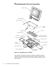
...contains the keyboard and the trackball), the display assembly (which contains the LCD), and the bottom case assembly (which contains many of the removable parts). 4-6 Dell Latitude XPi CD Service Manual Field-Replaceable Parts and Assemblies display assembly trackball assembly palmrest assembly CD-ROM EMI clip keyboard EMI clip left tilt-support foot...assembly dust cover for the Advanced Port Replicator connector I/O panel dust cover hard-disk drive assembly bottom case assembly right tilt-support foot main battery memory compartment cover CD-ROM/diskette drive assembly Figure 4-5.
...contains the keyboard and the trackball), the display assembly (which contains the LCD), and the bottom case assembly (which contains many of the removable parts). 4-6 Dell Latitude XPi CD Service Manual Field-Replaceable Parts and Assemblies display assembly trackball assembly palmrest assembly CD-ROM EMI clip keyboard EMI clip left tilt-support foot...assembly dust cover for the Advanced Port Replicator connector I/O panel dust cover hard-disk drive assembly bottom case assembly right tilt-support foot main battery memory compartment cover CD-ROM/diskette drive assembly Figure 4-5.
Service Manual
Page 46
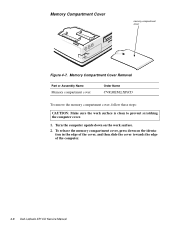
Memory Compartment Cover Removal Part or Assembly Name Memory compartment cover Order Name CVR,MEM,LXPiCD To remove the memory compartment cover, follow these steps: CAUTION: Make sure the work surface. 2. Turn the computer upside down on the work surface is clean to prevent scratching the computer cover. 1. Memory Compartment Cover memory compartment cover Figure 4-7. To release the memory compartment cover, press down on the identa- tion in the edge of the cover, and then slide the cover towards the edge of the computer. 4-8 Dell Latitude XPi CD Service Manual
Memory Compartment Cover Removal Part or Assembly Name Memory compartment cover Order Name CVR,MEM,LXPiCD To remove the memory compartment cover, follow these steps: CAUTION: Make sure the work surface. 2. Turn the computer upside down on the work surface is clean to prevent scratching the computer cover. 1. Memory Compartment Cover memory compartment cover Figure 4-7. To release the memory compartment cover, press down on the identa- tion in the edge of the cover, and then slide the cover towards the edge of the computer. 4-8 Dell Latitude XPi CD Service Manual


