
Service Manual
Page 2
... Corporation. Other trademarks and trade names may be used in this text: Dell, the DELL logo, and Latitude are registered trademarks of Intel Corporation; Intel and Pentium are registered trademarks of International Business Machines Corporation. Information in this manual is subject to either the entities claiming the marks and names or their products. All...
... Corporation. Other trademarks and trade names may be used in this text: Dell, the DELL logo, and Latitude are registered trademarks of Intel Corporation; Intel and Pentium are registered trademarks of International Business Machines Corporation. Information in this manual is subject to either the entities claiming the marks and names or their products. All...

Service Manual
Page 8
... for how to information provided in this manual, there may be blocks of IBM®-compatible PCs and prior training in italic type. In addition to avoid the problem. Warnings, Cautions, and Notes Throughout this manual, Dell provides the Reference and Troubleshooting Guide for... troubleshooting procedures and instructions on using the Dell diagnostics to service Dell portable computers is a basic knowledge of text printed in bold type or in...
... for how to information provided in this manual, there may be blocks of IBM®-compatible PCs and prior training in italic type. In addition to avoid the problem. Warnings, Cautions, and Notes Throughout this manual, Dell provides the Reference and Troubleshooting Guide for... troubleshooting procedures and instructions on using the Dell diagnostics to service Dell portable computers is a basic knowledge of text printed in bold type or in...

Service Manual
Page 10
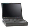
Front View of the Notebook Computer 1-2 Dell Latitude XPi CD Service Manual Physical Description display assembly LCD panel keyboard trackball assembly display assembly latch indicator panel microphone tilt-support foot (2) infrared port diskette drive main battery assembly speaker bottom case assembly CD-ROM drive Figure 1-1.
Front View of the Notebook Computer 1-2 Dell Latitude XPi CD Service Manual Physical Description display assembly LCD panel keyboard trackball assembly display assembly latch indicator panel microphone tilt-support foot (2) infrared port diskette drive main battery assembly speaker bottom case assembly CD-ROM drive Figure 1-1.

Service Manual
Page 12
Diskette-Drive Access Indicator The diskette-drive access indicator is a green LED. Hard-Disk/CD-ROM Drive Access Indicator The hard-disk/CD-ROM drive access indicator is a green LED. The low-battery indicator turns on and the speaker emits five beeps. • ..., the power/suspend indicator lights up constantly to or from the hard-disk drive or the CD-ROM. PC Card Access Indicator The PC Card access indicator is fully charged. 1-4 Dell Latitude XPi CD Service Manual This indicator is being transferred to 8 percent of its fully charged condition. The portable computer has...
Diskette-Drive Access Indicator The diskette-drive access indicator is a green LED. Hard-Disk/CD-ROM Drive Access Indicator The hard-disk/CD-ROM drive access indicator is a green LED. The low-battery indicator turns on and the speaker emits five beeps. • ..., the power/suspend indicator lights up constantly to or from the hard-disk drive or the CD-ROM. PC Card Access Indicator The PC Card access indicator is fully charged. 1-4 Dell Latitude XPi CD Service Manual This indicator is being transferred to 8 percent of its fully charged condition. The portable computer has...

Service Manual
Page 14
... by the diskette drive controller to indicate that the output buffer of the integrated trackball or external PS/2 mouse is full IRQ13 Reserved for the CD-ROM drive 1-6 Dell Latitude XPi CD Service Manual
... by the diskette drive controller to indicate that the output buffer of the integrated trackball or external PS/2 mouse is full IRQ13 Reserved for the CD-ROM drive 1-6 Dell Latitude XPi CD Service Manual

Service Manual
Page 16
... ES690 wavetable music synthesizer, ES938 3D audio spatializer Stereo conversion 16 bit (analog-to-digital and digitalto-analog) FM music synthesizer 20-voice, 72-operator 1-8 Dell Latitude XPi CD Service Manual Table 1-2.
... ES690 wavetable music synthesizer, ES938 3D audio spatializer Stereo conversion 16 bit (analog-to-digital and digitalto-analog) FM music synthesizer 20-voice, 72-operator 1-8 Dell Latitude XPi CD Service Manual Table 1-2.
Service Manual
Page 18
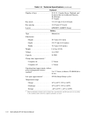
....4 VDC Capacity 36 WH Charge time (approximate):2 Computer on 2.5 hours Computer off 1.5 hours Operating time (approximate, with no power management features enabled)2 2 to 3.5 hours (without a CD-ROM drive in use) Life span (approximate)2 400 discharge/charge cycles Temperature range: Charge 10° to 40°C (50° to 104°F) Discharge... features such as charge time, operating time, and life span can vary according to the conditions under which the computer and battery are used. 1-10 Dell Latitude XPi CD Service Manual Table 1-2.
....4 VDC Capacity 36 WH Charge time (approximate):2 Computer on 2.5 hours Computer off 1.5 hours Operating time (approximate, with no power management features enabled)2 2 to 3.5 hours (without a CD-ROM drive in use) Life span (approximate)2 400 discharge/charge cycles Temperature range: Charge 10° to 40°C (50° to 104°F) Discharge... features such as charge time, operating time, and life span can vary according to the conditions under which the computer and battery are used. 1-10 Dell Latitude XPi CD Service Manual Table 1-2.

Service Manual
Page 20
Table 1-2. Technical Specifications (Continued) CD-ROM Drive3 (Continued) Access time: Random 250 m/sec Full-stroke 550 m/sec Memory buffer 128 KB Physical (Computer) Height 63.0 mm (2.48 inches) Width 280.9 ...) Maximum vibration: Operating 0.51 GRMS, using a random-vibration spectrum that simulates truck shipment Storage 1.1 GRMS, using a random-vibration spectrum that simulates air/truck shipment 3 The CD-ROM drive in your computer may have different specifications. 1-12 Dell Latitude XPi CD Service Manual
Table 1-2. Technical Specifications (Continued) CD-ROM Drive3 (Continued) Access time: Random 250 m/sec Full-stroke 550 m/sec Memory buffer 128 KB Physical (Computer) Height 63.0 mm (2.48 inches) Width 280.9 ...) Maximum vibration: Operating 0.51 GRMS, using a random-vibration spectrum that simulates truck shipment Storage 1.1 GRMS, using a random-vibration spectrum that simulates air/truck shipment 3 The CD-ROM drive in your computer may have different specifications. 1-12 Dell Latitude XPi CD Service Manual

Service Manual
Page 23
... is making any attached peripherals, including making an error, such as typing an incorrect key combination or entering a command incorrectly. No. puter problem. Dell recommends that can help you perform these steps: 1. Proceed to duplicate the problem by repeating the operations he or she was performing at the time... the problem, follow these procedures in the order they are presented in the online System User's Guide. 2. See "Maintaining Your Computer" in this manual. Chapter 2 Initial Procedures This chapter describes initial procedures that you diagnose a com-
... is making any attached peripherals, including making an error, such as typing an incorrect key combination or entering a command incorrectly. No. puter problem. Dell recommends that can help you perform these steps: 1. Proceed to duplicate the problem by repeating the operations he or she was performing at the time... the problem, follow these procedures in the order they are presented in the online System User's Guide. 2. See "Maintaining Your Computer" in this manual. Chapter 2 Initial Procedures This chapter describes initial procedures that you diagnose a com-

Service Manual
Page 24
... to room temperature, reconnect it to a cooler location. The computer is not allowed to cool, the battery stops charging before it reaches full capacity. 2-2 Dell Latitude XPi CD Service Manual If the computer is in suspend mode. Look at the indicators to determine which of any obvious physical damage. If the computer does not turn...
... to room temperature, reconnect it to a cooler location. The computer is not allowed to cool, the battery stops charging before it reaches full capacity. 2-2 Dell Latitude XPi CD Service Manual If the computer is in suspend mode. Look at the indicators to determine which of any obvious physical damage. If the computer does not turn...

Service Manual
Page 26
...the Boot Routine After you perform a visual inspection as appropriate. • Beep codes - Dell recommends that users make copies of beeps that indicates an error condition. Turn off the computer...subsystem. 4. Do these indicators fail to or from a diagnostics diskette and, while the boot routine is a series of the Dell diagnostics diskette. No. If either of these indicators light up and remain on any of the keyboard. A beep code is running... the Boot Routine." Yes. 15. Turn on . If a system error message displays, go to Table 3-2. 2-4 Dell Latitude XPi CD Service Manual
...the Boot Routine After you perform a visual inspection as appropriate. • Beep codes - Dell recommends that users make copies of beeps that indicates an error condition. Turn off the computer...subsystem. 4. Do these indicators fail to or from a diagnostics diskette and, while the boot routine is a series of the Dell diagnostics diskette. No. If either of these indicators light up and remain on any of the keyboard. A beep code is running... the Boot Routine." Yes. 15. Turn on . If a system error message displays, go to Table 3-2. 2-4 Dell Latitude XPi CD Service Manual

Service Manual
Page 30
... memory controller faulty (system board faulty) System board faulty Reserve battery faulty or system board faulty System board faulty System board faulty System board faulty 3-2 Dell Latitude XPi CD Service Manual Table 3-1.
... memory controller faulty (system board faulty) System board faulty Reserve battery faulty or system board faulty System board faulty System board faulty System board faulty 3-2 Dell Latitude XPi CD Service Manual Table 3-1.

Service Manual
Page 32
... reading PCMCIA card Diskette subsystem failed to respond to initialize. Defective or unformatted diskette. System board faulty. PC Card software faulty or incorrectly installed. 3-4 Dell Latitude XPi CD Service Manual System Setup contains incorrect settings. Diskette is failing (usually preceded by memory error message). The diskette may be completed. seek failure kette in drive. Diskette...
... reading PCMCIA card Diskette subsystem failed to respond to initialize. Defective or unformatted diskette. System board faulty. PC Card software faulty or incorrectly installed. 3-4 Dell Latitude XPi CD Service Manual System Setup contains incorrect settings. Diskette is failing (usually preceded by memory error message). The diskette may be completed. seek failure kette in drive. Diskette...

Service Manual
Page 34
... Keyboard key(s) jammed. For external keyboard or keypad, cable or connector loose or keyboard faulty. Table 3-2. The software in keyboard, keyboard faulty. Faulty application program 3-6 Dell Latitude XPi CD Service Manual
... Keyboard key(s) jammed. For external keyboard or keypad, cable or connector loose or keyboard faulty. Table 3-2. The software in keyboard, keyboard faulty. Faulty application program 3-6 Dell Latitude XPi CD Service Manual

Service Manual
Page 36
... the computer. Tests the video subsystem • Keyboard - Tests the IDE hard-disk drive subsystem • IDE CD-ROM Drives - Tests the system board's primary functions • Video - Tests the CD-ROM drive subsystem 3-8 Dell Latitude XPi CD Service Manual System Error Messages (Continued) Message Definition Probable Causes Seek error MS-DOS unable to System board faulty...
... the computer. Tests the video subsystem • Keyboard - Tests the IDE hard-disk drive subsystem • IDE CD-ROM Drives - Tests the system board's primary functions • Video - Tests the CD-ROM drive subsystem 3-8 Dell Latitude XPi CD Service Manual System Error Messages (Continued) Message Definition Probable Causes Seek error MS-DOS unable to System board faulty...
Service Manual
Page 40
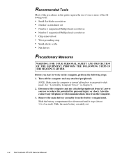
... the potential for personal injury or shock. Disconnect the computer and any attached peripherals from the battery compartment. Slide the main battery assembly out. 4-2 Dell Latitude XPi CD Service Manual Also disconnect any attached peripherals. Remove the main battery assembly from AC power sources to -disk mode. Recommended Tools Most of the procedures in this...
... the potential for personal injury or shock. Disconnect the computer and any attached peripherals from the battery compartment. Slide the main battery assembly out. 4-2 Dell Latitude XPi CD Service Manual Also disconnect any attached peripherals. Remove the main battery assembly from AC power sources to -disk mode. Recommended Tools Most of the procedures in this...
Service Manual
Page 42
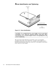
... result. Screw Identification 35 mm match length here CAUTION: It is properly aligned with its corresponding hole, and avoid overtightening. Also, a graphic for correct length. 4-4 Dell Latitude XPi CD Service Manual Screw Identification and Tightening A6 (35 mm) (screw A6 is included in the illustration.
... result. Screw Identification 35 mm match length here CAUTION: It is properly aligned with its corresponding hole, and avoid overtightening. Also, a graphic for correct length. 4-4 Dell Latitude XPi CD Service Manual Screw Identification and Tightening A6 (35 mm) (screw A6 is included in the illustration.
Service Manual
Page 44
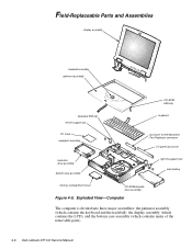
...), the display assembly (which contains the LCD), and the bottom case assembly (which contains many of the removable parts). 4-6 Dell Latitude XPi CD Service Manual Field-Replaceable Parts and Assemblies display assembly trackball assembly palmrest assembly CD-ROM EMI clip keyboard EMI clip left tilt-support foot keyboard PC Card superpart assembly dust cover for the...
...), the display assembly (which contains the LCD), and the bottom case assembly (which contains many of the removable parts). 4-6 Dell Latitude XPi CD Service Manual Field-Replaceable Parts and Assemblies display assembly trackball assembly palmrest assembly CD-ROM EMI clip keyboard EMI clip left tilt-support foot keyboard PC Card superpart assembly dust cover for the...
Service Manual
Page 46
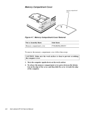
tion in the edge of the cover, and then slide the cover towards the edge of the computer. 4-8 Dell Latitude XPi CD Service Manual Turn the computer upside down on the work surface is clean to prevent scratching the computer cover. 1. To release the memory compartment cover, press down on the identa- Memory Compartment Cover Removal Part or Assembly Name Memory compartment cover Order Name CVR,MEM,LXPiCD To remove the memory compartment cover, follow these steps: CAUTION: Make sure the work surface. 2. Memory Compartment Cover memory compartment cover Figure 4-7.
tion in the edge of the cover, and then slide the cover towards the edge of the computer. 4-8 Dell Latitude XPi CD Service Manual Turn the computer upside down on the work surface is clean to prevent scratching the computer cover. 1. To release the memory compartment cover, press down on the identa- Memory Compartment Cover Removal Part or Assembly Name Memory compartment cover Order Name CVR,MEM,LXPiCD To remove the memory compartment cover, follow these steps: CAUTION: Make sure the work surface. 2. Memory Compartment Cover memory compartment cover Figure 4-7.
Service Manual
Page 48
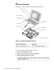
Remove any cables attached to prevent scratching the computer cover. 4-10 Dell Latitude XPi CD Service Manual Remove the hard-disk drive assembly. Disconnect any installed PC Card(s). 2. Palmrest Assembly Removal bottom case assembly Part or Assembly Name Palmrest ...1. CAUTION: Make sure the work surface is clean to the audio ports. 3. display assembly keyboard palmrest assembly trackball assembly trackball cable connector JTB CD-ROM EMI clip connector JKB1 connector JKB2 Figure 4-9. Palmrest Assembly The palmrest assembly consists of the trackball and the keyboard.
Remove any cables attached to prevent scratching the computer cover. 4-10 Dell Latitude XPi CD Service Manual Remove the hard-disk drive assembly. Disconnect any installed PC Card(s). 2. Palmrest Assembly Removal bottom case assembly Part or Assembly Name Palmrest ...1. CAUTION: Make sure the work surface is clean to the audio ports. 3. display assembly keyboard palmrest assembly trackball assembly trackball cable connector JTB CD-ROM EMI clip connector JKB1 connector JKB2 Figure 4-9. Palmrest Assembly The palmrest assembly consists of the trackball and the keyboard.


