
Latitude E-Family Re-Imaging Guide
Page 5
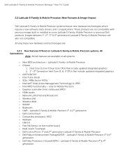
... o Chipset 1. These products are : 2.2.1 New Features Offered on Latitude E-Family & Mobile Precision systems, All Generations: Note: Not all systems o New BIOS architecture - Dell Latitude E-Family & Mobile Precision Reimage "How-To" Guide 2.2 Latitude E-Family & Mobile Precision New Features & Image Impact Dell Latitude E-Family & Mobile Precision systems feature new hardware technologies which require a... for Mobile Precision o Graphics controller (Intel, nVidia and AMD) o HDMI Audio o Network LoM (Intel and Broadcom) o Wireless LAN o Wireless WAN o WiMAX o Bluetooth o UWB -
... o Chipset 1. These products are : 2.2.1 New Features Offered on Latitude E-Family & Mobile Precision systems, All Generations: Note: Not all systems o New BIOS architecture - Dell Latitude E-Family & Mobile Precision Reimage "How-To" Guide 2.2 Latitude E-Family & Mobile Precision New Features & Image Impact Dell Latitude E-Family & Mobile Precision systems feature new hardware technologies which require a... for Mobile Precision o Graphics controller (Intel, nVidia and AMD) o HDMI Audio o Network LoM (Intel and Broadcom) o Wireless LAN o Wireless WAN o WiMAX o Bluetooth o UWB -
Latitude E-Family Re-Imaging Guide
Page 9
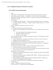
...based power management mechanism for E-Family 1st generation systems 1. Even if you do not need this driver) 1. Dell Latitude E-Family & Mobile Precision Reimage "How-To" Guide 2.4.2 Installation Sequence & Features at a Glance: 2.4.2.1 BIOS, Drivers and Firmware: o BIOS... & Mobile Precision 1st generation 2. Latitude E-Family & Mobile Precision 2nd, 3rd & 4th generations o Audio - Enables and enhances the Wireless LAN network adapter 2. Intel Rapid Storage Technology - Enables and enhances the UWB or Bluetooth Adapter 3. Enables and enhances the Broadband wireless Adapter ...
...based power management mechanism for E-Family 1st generation systems 1. Even if you do not need this driver) 1. Dell Latitude E-Family & Mobile Precision Reimage "How-To" Guide 2.4.2 Installation Sequence & Features at a Glance: 2.4.2.1 BIOS, Drivers and Firmware: o BIOS... & Mobile Precision 1st generation 2. Latitude E-Family & Mobile Precision 2nd, 3rd & 4th generations o Audio - Enables and enhances the Wireless LAN network adapter 2. Intel Rapid Storage Technology - Enables and enhances the UWB or Bluetooth Adapter 3. Enables and enhances the Broadband wireless Adapter ...
Latitude E-Family Re-Imaging Guide
Page 22
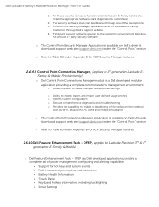
... The Control Point Security Manager Application is available on the notebook such as Wi-Fi, Bluetooth GPS, UWB, and mobile broadband - DFEP is a Dell developed modular application providing a complete communications management environment: o Allows the user to create ...Security Manager features 2.6.10 Dell Feature Enhancement Pack - Dell Latitude E-Family & Mobile Precision Reimage "How-To" Guide 1. The security software stack can be obtained through Dell's support website 4. Refer to Latitude Precision 3rd & 4th generation E-Family & Mobile) o Dell Feature Enhancement Pack - DFEP...
... The Control Point Security Manager Application is available on the notebook such as Wi-Fi, Bluetooth GPS, UWB, and mobile broadband - DFEP is a Dell developed modular application providing a complete communications management environment: o Allows the user to create ...Security Manager features 2.6.10 Dell Feature Enhancement Pack - Dell Latitude E-Family & Mobile Precision Reimage "How-To" Guide 1. The security software stack can be obtained through Dell's support website 4. Refer to Latitude Precision 3rd & 4th generation E-Family & Mobile) o Dell Feature Enhancement Pack - DFEP...
Latitude E-Family Re-Imaging Guide
Page 24
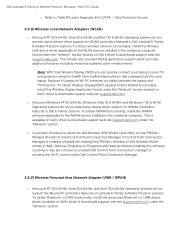
... Operating Systems do not support the Bluetooth controllers featured on Latitude E-Family & Mobile Precision systems. To obtain Bluetooth or UWB functionality, install the associated Bluetooth or UWB device drivers available on Dell's driver & downloads support web site (support.dell.com). Because it's based on Dell's driver & downloads support web site (support.dell.com). This is installed, uninstall the...
... Operating Systems do not support the Bluetooth controllers featured on Latitude E-Family & Mobile Precision systems. To obtain Bluetooth or UWB functionality, install the associated Bluetooth or UWB device drivers available on Dell's driver & downloads support web site (support.dell.com). Because it's based on Dell's driver & downloads support web site (support.dell.com). This is installed, uninstall the...

User Manual
Page 6
...trademark and owned by the Bluetooth® SIG, Inc. The Bluetooth® word mark is strictly forbidden. disclaims any use on your product is available at support.dell.com/manuals. Trademarks used in any manner whatsoever without notice. © 2012 Dell Inc. Intel®, ... Vista start button, and Office Outlook® are trademarks of Dell Inc. Reproduction of these materials in this text: Dell™, the DELL logo, Dell Precision™, Precision ON™, ExpressCharge™, Latitude™, Latitude ON™, OptiPlex™, Vostro™, and Wi-Fi Catcher...
...trademark and owned by the Bluetooth® SIG, Inc. The Bluetooth® word mark is strictly forbidden. disclaims any use on your product is available at support.dell.com/manuals. Trademarks used in any manner whatsoever without notice. © 2012 Dell Inc. Intel®, ... Vista start button, and Office Outlook® are trademarks of Dell Inc. Reproduction of these materials in this text: Dell™, the DELL logo, Dell Precision™, Precision ON™, ExpressCharge™, Latitude™, Latitude ON™, OptiPlex™, Vostro™, and Wi-Fi Catcher...

Owner's Manual
Page 3
... the Keyboard...19 Installing the Keyboard...21 Removing the Wireless Local Area Network (WLAN) Card 22 Installing the WLAN Card...22 Removing the Bluetooth Module...22 Installing the Bluetooth Module...23 Removing the Memory...24 Installing the Memory...24 Removing the Coin-Cell Battery...25 Installing the Coin-Cell Battery...25 Removing...
... the Keyboard...19 Installing the Keyboard...21 Removing the Wireless Local Area Network (WLAN) Card 22 Installing the WLAN Card...22 Removing the Bluetooth Module...22 Installing the Bluetooth Module...23 Removing the Memory...24 Installing the Memory...24 Removing the Coin-Cell Battery...25 Installing the Coin-Cell Battery...25 Removing...

Owner's Manual
Page 22
...the computer. Remove the base cover. 4. Connect the antenna cables to the computer. 4. Remove the base cover. 4. Remove the bluetooth cable from the computer. Installing the WLAN Card 1. Remove the battery. 3. Disconnect the antenna cables from the system board. 5.... Remove the WLAN card from its slot. 2. Removing the Bluetooth Module 1. Install: a) base cover b) battery 5. Follow the procedures in Before Working Inside Your Computer. 2. Removing the Wireless Local Area Network...
...the computer. Remove the base cover. 4. Connect the antenna cables to the computer. 4. Remove the base cover. 4. Remove the bluetooth cable from the computer. Installing the WLAN Card 1. Remove the battery. 3. Disconnect the antenna cables from the system board. 5.... Remove the WLAN card from its slot. 2. Removing the Bluetooth Module 1. Install: a) base cover b) battery 5. Follow the procedures in Before Working Inside Your Computer. 2. Removing the Wireless Local Area Network...

Owner's Manual
Page 23
6. Remove the screw that secures the bluetooth module to the bluetooth card. 2. Remove the bluetooth module from the bluetooth module. Disconnect the bluetooth cable from the computer. 8. Installing the Bluetooth Module 1. Connect the bluetooth cable to the computer. 7. Connect the other end of the bluetooth cable to the system board. 23
6. Remove the screw that secures the bluetooth module to the bluetooth card. 2. Remove the bluetooth module from the bluetooth module. Disconnect the bluetooth cable from the computer. 8. Installing the Bluetooth Module 1. Connect the bluetooth cable to the computer. 7. Connect the other end of the bluetooth cable to the system board. 23

Owner's Manual
Page 24
... system board at 45-degree angle. 6. Insert the memory module into the memory socket. 2. Tighten the screw to secure the bluetooth card to remove the second memory module. Place the bluetooth card in its connector on the system board by drawing the module from the memory module until it pops up. 5. Press...
... system board at 45-degree angle. 6. Insert the memory module into the memory socket. 2. Tighten the screw to secure the bluetooth card to remove the second memory module. Place the bluetooth card in its connector on the system board by drawing the module from the memory module until it pops up. 5. Press...

Owner's Manual
Page 26
Remove the screws that secure the palmrest assembly to the base of the computer. 5. e) optical drive f) base cover g) keyboard trim h) keyboard i) bluetooth module 3. Disconnect the touchpad cable from the system board. 6. Disconnect the LED-board cable from the system board. 26 Remove the screws that secure the palmrest assembly to the front of the computer. 4.
Remove the screws that secure the palmrest assembly to the base of the computer. 5. e) optical drive f) base cover g) keyboard trim h) keyboard i) bluetooth module 3. Disconnect the touchpad cable from the system board. 6. Disconnect the LED-board cable from the system board. 26 Remove the screws that secure the palmrest assembly to the front of the computer. 4.

Owner's Manual
Page 27
... palmrest up and away from the system board. 8. Connect the following cables to its original position in the computer and snap it into place. 2. Install: a) bluetooth module b) keyboard c) keyboard trim d) base cover e) optical drive 27 Align the palmrest assembly to the system board: a) power LED cable b) touchpad cable c) LED-board cable...
... palmrest up and away from the system board. 8. Connect the following cables to its original position in the computer and snap it into place. 2. Install: a) bluetooth module b) keyboard c) keyboard trim d) base cover e) optical drive 27 Align the palmrest assembly to the system board: a) power LED cable b) touchpad cable c) LED-board cable...

Owner's Manual
Page 28
Follow the procedures in Before Working Inside Your Computer. 2. Removing the Media Board 1. Remove the screws that secure the media board to the computer. 5. Remove: a) SD card b) ExpressCard c) battery d) hard drive e) optical drive f) base cover g) keyboard trim h) keyboard i) bluetooth module j) palmrest 3. Remove the media board from the system board. 4. Disconnect the media-board cable from the computer. 28 Follow the procedures in After Working Inside Your Computer. f) hard drive g) battery h) ExpressCard i) SD card 6.
Follow the procedures in Before Working Inside Your Computer. 2. Removing the Media Board 1. Remove the screws that secure the media board to the computer. 5. Remove: a) SD card b) ExpressCard c) battery d) hard drive e) optical drive f) base cover g) keyboard trim h) keyboard i) bluetooth module j) palmrest 3. Remove the media board from the system board. 4. Disconnect the media-board cable from the computer. 28 Follow the procedures in After Working Inside Your Computer. f) hard drive g) battery h) ExpressCard i) SD card 6.

Owner's Manual
Page 29
Disconnect the ExpressCard cable from the system board. 29 Place the media board in Before Working Inside Your Computer. 2. Install: a) palmrest b) bluetooth module c) keyboard d) keyboard trim e) base cover f) optical drive g) hard drive h) battery i) ExpressCard j) SD card 5. Removing the ExpressCard Cage 1. Follow the procedures in its ...media-board cable to secure the media board. 3. Remove: a) SD card b) ExpressCard c) battery d) hard drive e) optical drive f) base cover g) keyboard trim h) keyboard i) bluetooth module j) palmrest 3. Tighten the screws to the system board. 4.
Disconnect the ExpressCard cable from the system board. 29 Place the media board in Before Working Inside Your Computer. 2. Install: a) palmrest b) bluetooth module c) keyboard d) keyboard trim e) base cover f) optical drive g) hard drive h) battery i) ExpressCard j) SD card 5. Removing the ExpressCard Cage 1. Follow the procedures in its ...media-board cable to secure the media board. 3. Remove: a) SD card b) ExpressCard c) battery d) hard drive e) optical drive f) base cover g) keyboard trim h) keyboard i) bluetooth module j) palmrest 3. Tighten the screws to the system board. 4.

Owner's Manual
Page 30
4. Installing the ExpressCard Cage 1. Remove the screws that secure the ExpressCard cage to the system board. 4. Connect the ExpressCard cable to the computer. 5. Tighten the screws to secure the ExpressCard cage to the computer. 3. Insert the ExpressCard cage into its compartment. 2. Remove the ExpressCard cage from the computer. Install: a) palmrest b) bluetooth module c) keyboard d) keyboard trim e) base cover f) optical drive g) hard drive h) battery i) ExpressCard 30
4. Installing the ExpressCard Cage 1. Remove the screws that secure the ExpressCard cage to the system board. 4. Connect the ExpressCard cable to the computer. 5. Tighten the screws to secure the ExpressCard cage to the computer. 3. Insert the ExpressCard cage into its compartment. 2. Remove the ExpressCard cage from the computer. Install: a) palmrest b) bluetooth module c) keyboard d) keyboard trim e) base cover f) optical drive g) hard drive h) battery i) ExpressCard 30

Owner's Manual
Page 31
Follow the procedures in After Working Inside Your Computer. Release the speaker cable from the system board. 4. Follow the procedures in Before Working Inside Your Computer. 2. j) SD card 5. Remove: a) SD card b) ExpressCard c) battery d) hard drive e) optical drive f) base cover g) keyboard trim h) keyboard i) bluetooth module j) palmrest 3. Disconnect the speaker cable from the computer. 5. Remove the screws that secure the speakers to the computer. 31 Removing the Speakers 1.
Follow the procedures in After Working Inside Your Computer. Release the speaker cable from the system board. 4. Follow the procedures in Before Working Inside Your Computer. 2. j) SD card 5. Remove: a) SD card b) ExpressCard c) battery d) hard drive e) optical drive f) base cover g) keyboard trim h) keyboard i) bluetooth module j) palmrest 3. Disconnect the speaker cable from the computer. 5. Remove the screws that secure the speakers to the computer. 31 Removing the Speakers 1.

Owner's Manual
Page 32
6. Install: a) palmrest b) bluetooth module c) keyboard d) keyboard trim e) base cover f) optical drive g) hard drive h) battery i) ExpressCard j) SD card 4. Remove: a) SD card b) ExpressCard c) battery d) hard drive e) optical drive 32 Route ...
6. Install: a) palmrest b) bluetooth module c) keyboard d) keyboard trim e) base cover f) optical drive g) hard drive h) battery i) ExpressCard j) SD card 4. Remove: a) SD card b) ExpressCard c) battery d) hard drive e) optical drive 32 Route ...

Owner's Manual
Page 33
... Covers 1. Remove the display-hinge covers from the computer. Tighten the screws to secure the display hinge covers to the computer. 4. Remove: 33 Install: a) palmrest b) bluetooth module c) keyboard d) keyboard trim e) base cover f) optical drive g) hard drive h) battery i) ExpressCard j) SD card 3. Follow the procedures in Before Working Inside Your Computer. 2. ...-hinge covers to the computer. 2. Removing the Display Assembly 1. Follow the procedures in After Working Inside Your Computer. f) base cover g) keyboard trim h) keyboard i) bluetooth module j) palmrest 3.
... Covers 1. Remove the display-hinge covers from the computer. Tighten the screws to secure the display hinge covers to the computer. 4. Remove: 33 Install: a) palmrest b) bluetooth module c) keyboard d) keyboard trim e) base cover f) optical drive g) hard drive h) battery i) ExpressCard j) SD card 3. Follow the procedures in Before Working Inside Your Computer. 2. ...-hinge covers to the computer. 2. Removing the Display Assembly 1. Follow the procedures in After Working Inside Your Computer. f) base cover g) keyboard trim h) keyboard i) bluetooth module j) palmrest 3.

Owner's Manual
Page 34
Remove the screws that secures the left display hinge to the computer. 5. Remove the screw that secure the display assembly to the computer. 6. Remove the screws that secure the Low-Voltage Differential Signaling (LVDS) support bracket. 34 Release the antenna cables from their routing on the computer. 4. a) SD card b) ExpressCard c) battery d) hard drive e) optical drive f) base cover g) keyboard trim h) keyboard i) bluetooth module j) palmrest 3.
Remove the screws that secures the left display hinge to the computer. 5. Remove the screw that secure the display assembly to the computer. 6. Remove the screws that secure the Low-Voltage Differential Signaling (LVDS) support bracket. 34 Release the antenna cables from their routing on the computer. 4. a) SD card b) ExpressCard c) battery d) hard drive e) optical drive f) base cover g) keyboard trim h) keyboard i) bluetooth module j) palmrest 3.

Owner's Manual
Page 36
... Working Inside Your Computer. 2. Route the antenna cables through the opening on the system board. 2. Route the antennae cables through their routing channel. 7. Install: a) palmrest b) bluetooth module c) keyboard d) keyboard trim e) base cover f) optical drive g) hard drive h) battery i) ExpressCard j) SD card 8. Connect the LVDS cable to the system board. 4. Remove: a) SD card...
... Working Inside Your Computer. 2. Route the antenna cables through the opening on the system board. 2. Route the antennae cables through their routing channel. 7. Install: a) palmrest b) bluetooth module c) keyboard d) keyboard trim e) base cover f) optical drive g) hard drive h) battery i) ExpressCard j) SD card 8. Connect the LVDS cable to the system board. 4. Remove: a) SD card...

Owner's Manual
Page 38
Connect the power connector cable to the system board: a) speaker b) ExpressCard c) coin-cell battery 4. Installing the System Board 1. Install : a) display assembly b) display hinge covers c) media board d) palmrest e) bluetooth module f) keyboard 38 Connect the following cables to the system board. 2. Remove the system board from the system board. 9. Tighten the screws to secure the system board to the computer. 3. 8. Disconnect the power-connector cable from the computer.
Connect the power connector cable to the system board: a) speaker b) ExpressCard c) coin-cell battery 4. Installing the System Board 1. Install : a) display assembly b) display hinge covers c) media board d) palmrest e) bluetooth module f) keyboard 38 Connect the following cables to the system board. 2. Remove the system board from the system board. 9. Tighten the screws to secure the system board to the computer. 3. 8. Disconnect the power-connector cable from the computer.

