E-Family Re-Image Guide
Page 10
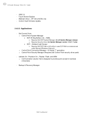
...: o Control Point System Manager • DCP All Day Battery Life - Latitude On / Precision On - Backup & Recovery Manager Dell Confidential ADBL • Requires Dell DCP System Manager (for all System Manager release) • Requires Security driver (for System Manager version 1.0 & 1.1 only) •...Communication solution that is not desired and under Microsoft Windows Vista only o Control Point Connection Manager - Ambient Light Sensor • Requires Dell DCP-SM or ALS utility in case DCP-SM is designed to provide quick access to business critical data - Control Vault Firmware ...
...: o Control Point System Manager • DCP All Day Battery Life - Latitude On / Precision On - Backup & Recovery Manager Dell Confidential ADBL • Requires Dell DCP System Manager (for all System Manager release) • Requires Security driver (for System Manager version 1.0 & 1.1 only) •...Communication solution that is not desired and under Microsoft Windows Vista only o Control Point Connection Manager - Ambient Light Sensor • Requires Dell DCP-SM or ALS utility in case DCP-SM is designed to provide quick access to business critical data - Control Vault Firmware ...
E-Family Re-Image Guide
Page 11
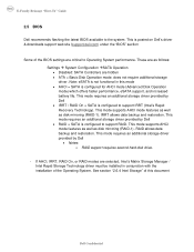
...) which offers faster performance, eSATA support, and increased battery life. See section "2.6.4 Intel Storage" of the Operating System. These are as follows: Settings System Configuration SATA Operation • Disabled: SATA Controllers are selected, Intel's Matrix Storage Manager / Intel Rapid Storage Technology driver must be installed in this document Dell Confidential
...) which offers faster performance, eSATA support, and increased battery life. See section "2.6.4 Intel Storage" of the Operating System. These are as follows: Settings System Configuration SATA Operation • Disabled: SATA Controllers are selected, Intel's Matrix Storage Manager / Intel Rapid Storage Technology driver must be installed in this document Dell Confidential
E-Family Re-Image Guide
Page 17
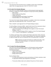
... be obtained through one of power management configuring and alerting capabilities: o Battery Status o Power Scheme and Sleep Mode o Display and Devices o Keyboard Backlighting and Hotkeys Customization o Extended Battery Life / All Day Battery Life - For All Day Battery Life feature (ADBL), install the Dell Control Point components offered by installing ALS utility in case Control Point...
... be obtained through one of power management configuring and alerting capabilities: o Battery Status o Power Scheme and Sleep Mode o Display and Devices o Keyboard Backlighting and Hotkeys Customization o Extended Battery Life / All Day Battery Life - For All Day Battery Life feature (ADBL), install the Dell Control Point components offered by installing ALS utility in case Control Point...
E-Family Re-Image Guide
Page 28
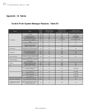
...Pro Photo RGB/Kodak or Adobe color v1.3 RGB LED Displays (17" only) settings (certain panels only) Availablity of Feature when Dell provides drivers/middleware, but with No screen pop-up display Yes N/A No Yes N/A Yes Yes N/A No Yes N/A Through BIOS ...Through BIOS Yes N/A Through BIOS Yes N/A No Yes N/A No Yes N/A No Dell Confidential v1.0 battery charge enable/disable status v1.0 Network card power management v1.0 Extended Battery Life/ All Day Battery Life. Table B1 Category Power Manager Display settings Function Keys Hot Key customizaton Keyboard ...
...Pro Photo RGB/Kodak or Adobe color v1.3 RGB LED Displays (17" only) settings (certain panels only) Availablity of Feature when Dell provides drivers/middleware, but with No screen pop-up display Yes N/A No Yes N/A Yes Yes N/A No Yes N/A Through BIOS ...Through BIOS Yes N/A Through BIOS Yes N/A No Yes N/A No Yes N/A No Dell Confidential v1.0 battery charge enable/disable status v1.0 Network card power management v1.0 Extended Battery Life/ All Day Battery Life. Table B1 Category Power Manager Display settings Function Keys Hot Key customizaton Keyboard ...
Setup Features and Information Techsheet
Page 2
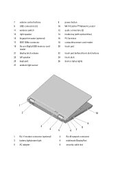
...-card reader 20 touch pad 22 touch pad buttons/track stick buttons 24 track stick 26 device status lights 1 2 10 3 4 1 RJ-11 modem connector (optional) 3 battery light/power light 5 AC adapter 9 8 5 67 2 RJ-45 network connector 4 multimode DisplayPort 6 security cable slot
...-card reader 20 touch pad 22 touch pad buttons/track stick buttons 24 track stick 26 device status lights 1 2 10 3 4 1 RJ-11 modem connector (optional) 3 battery light/power light 5 AC adapter 9 8 5 67 2 RJ-45 network connector 4 multimode DisplayPort 6 security cable slot
Setup Features and Information Techsheet
Page 6
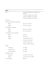
...: 4-cell and 6-cell lithium-ion batteries: Depth Height 9-cell lithium-ion batteries: Depth Height 12-cell lithium-ion slice batteries: Depth Height Weight Voltage: 4-cell battery 6-cell and 9-cell 12-cell slice battery Temperature range: Operating Storage Coin-cell battery 12-cell "smart" lithium ion prismatic slice (84 Whr) 9-cell "smart" lithium ion (85 Whr) 6-cell...
...: 4-cell and 6-cell lithium-ion batteries: Depth Height 9-cell lithium-ion batteries: Depth Height 12-cell lithium-ion slice batteries: Depth Height Weight Voltage: 4-cell battery 6-cell and 9-cell 12-cell slice battery Temperature range: Operating Storage Coin-cell battery 12-cell "smart" lithium ion prismatic slice (84 Whr) 9-cell "smart" lithium ion (85 Whr) 6-cell...

Replacing the System Board
Page 3
.... The setup utility will not function properly without a Service Tag. Programming the Service Tag After replacing the system board for Latitude E5400, E5500, and Dell Precision M6400 Mobile Workstations, you need to enter the system setup program. 2 Enter the correct Service Tag. 3 Perform one... off, connect the AC adapter, and then turn the computer back on. NOTE: Latitude and Dell Precision E-Series Workstation computers configured with iAMT® receive this error. NOTE: The battery light on the computer flashes blue and amber during this message only after the iAMT initialization...
.... The setup utility will not function properly without a Service Tag. Programming the Service Tag After replacing the system board for Latitude E5400, E5500, and Dell Precision M6400 Mobile Workstations, you need to enter the system setup program. 2 Enter the correct Service Tag. 3 Perform one... off, connect the AC adapter, and then turn the computer back on. NOTE: Latitude and Dell Precision E-Series Workstation computers configured with iAMT® receive this error. NOTE: The battery light on the computer flashes blue and amber during this message only after the iAMT initialization...
Service Manual
Page 1
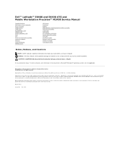
... Trademarks used in this document to refer to either the entities claiming the marks and names or their products. Dell™ Latitude™ E6400 and E6400 ATG and Mobile Workstation Precision™ M2400 Service Manual Troubleshooting Working on Your Computer Base Assembly Hinge Covers Hard ...Grill/Fingerprint Reader Assembly Palm Rest Assembly Card Cage 1394 Card RJ-11 Modem Connector System Board Assembly I/O Card DC Power Cable Battery Latch Assembly Display Assembly Flashing the BIOS Notes, Notices, and Cautions NOTE: A NOTE indicates important information that helps you how...
... Trademarks used in this document to refer to either the entities claiming the marks and names or their products. Dell™ Latitude™ E6400 and E6400 ATG and Mobile Workstation Precision™ M2400 Service Manual Troubleshooting Working on Your Computer Base Assembly Hinge Covers Hard ...Grill/Fingerprint Reader Assembly Palm Rest Assembly Card Cage 1394 Card RJ-11 Modem Connector System Board Assembly I/O Card DC Power Cable Battery Latch Assembly Display Assembly Flashing the BIOS Notes, Notices, and Cautions NOTE: A NOTE indicates important information that helps you how...

Service Manual
Page 5
... Remove the display assembly (see Replacing the Coin-Cell Battery). 6. Replace the I/O card (see Replacing the I /O Card). Replace the coin-cell battery (see Removing the Display Assembly (E6400 and M2400) or Removing the Display Assembly (E6400 ATG)). 11. Replace the heatsink assembly (see Removing a... Assembly). 15. Replacing the Base Assembly 1. Remove the palm rest assembly (see Replacing the Display Assembly (E6400 and M2400) or Replacing the Display Assembly (E6400 ATG)). 12. Remove the I/O card (see Removing the Hinge Covers). 6. Replace the display assembly (see...
... Remove the display assembly (see Replacing the Coin-Cell Battery). 6. Replace the I/O card (see Replacing the I /O Card). Replace the coin-cell battery (see Removing the Display Assembly (E6400 and M2400) or Removing the Display Assembly (E6400 ATG)). 11. Replace the heatsink assembly (see Removing a... Assembly). 15. Replacing the Base Assembly 1. Remove the palm rest assembly (see Replacing the Display Assembly (E6400 and M2400) or Replacing the Display Assembly (E6400 ATG)). 12. Remove the I/O card (see Removing the Hinge Covers). 6. Replace the display assembly (see...
Service Manual
Page 7
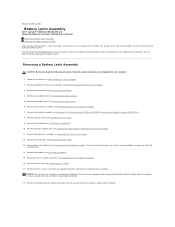
... modules, or processor from the system board. 14. Back to Contents Page Battery Latch Assembly Dell™ Latitude™ E6400 and E6400 ATG and Mobile Workstation Precision™ M2400 Service Manual Removing a Battery Latch Assembly Replacing the Battery Latch Assembly There are two battery latches, a left battery latches. Remove the right speaker grill (see Removing the Right Speaker Grill...
... modules, or processor from the system board. 14. Back to Contents Page Battery Latch Assembly Dell™ Latitude™ E6400 and E6400 ATG and Mobile Workstation Precision™ M2400 Service Manual Removing a Battery Latch Assembly Replacing the Battery Latch Assembly There are two battery latches, a left battery latches. Remove the right speaker grill (see Removing the Right Speaker Grill...
Service Manual
Page 8
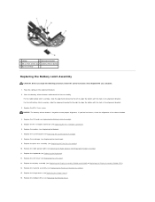
...Replace the I/O card (see Replacing the Processor Heatsink Assembly). 15. Replace the heatsink assembly (see Replacing the Battery Latch Assembly). 5. Place the battery release button underneath the base assembly. Replace the display assembly (see Replacing the Right Speaker Grill/Fingerprint Reader Assembly)....11. Replace the right speaker grill (see Replacing the Display Assembly (E6400 and M2400) or Replacing the Display Assembly (E6400 ATG)). 14. For the left to ensure proper alignment. NOTICE: The battery release button is keyed to align the button with your computer. ...
...Replace the I/O card (see Replacing the Processor Heatsink Assembly). 15. Replace the heatsink assembly (see Replacing the Battery Latch Assembly). 5. Place the battery release button underneath the base assembly. Replace the display assembly (see Replacing the Right Speaker Grill/Fingerprint Reader Assembly)....11. Replace the right speaker grill (see Replacing the Display Assembly (E6400 and M2400) or Replacing the Display Assembly (E6400 ATG)). 14. For the left to ensure proper alignment. NOTICE: The battery release button is keyed to align the button with your computer. ...
Service Manual
Page 10
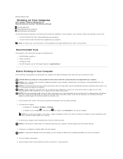
...wrist grounding strap or by periodically touching an unpainted metal surface, such as a processor by its edges or by Dell is off your computer. Slide the battery release latches toward each procedure assumes that: l You have read the safety information that shipped with locking tabs, ... them in your computer, and then unplug it from the battery bay before you must remove the battery from the network wall jack. 4. Back to Contents Page Working on Your Computer Dell™ Latitude™ E6400 and E6400 ATG and Mobile Workstation Precision™ M2400 Service Manual Recommended ...
...wrist grounding strap or by periodically touching an unpainted metal surface, such as a processor by its edges or by Dell is off your computer. Slide the battery release latches toward each procedure assumes that: l You have read the safety information that shipped with locking tabs, ... them in your computer, and then unplug it from the battery bay before you must remove the battery from the network wall jack. 4. Back to Contents Page Working on Your Computer Dell™ Latitude™ E6400 and E6400 ATG and Mobile Workstation Precision™ M2400 Service Manual Recommended ...
Service Manual
Page 11
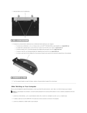
... on your computer. Turn the computer topside up and ease the port cover away from the E6400 ATG, fit the port cover into the connectors on your battery slice or on support.dell.com. Connect any cards, such as an ExpressCard, see the E-Port User's Guide or the... a port cover from the E6400 ATG, lift up , open the display, and press the power button to ground the system board. l To undock from a docking station, see the Dell™ Technology Guide on the back of the battery bay. 1 battery 2 battery release latches (2) 8. After Working on support.dell.com. NOTE: To avoid ...
... on your computer. Turn the computer topside up and ease the port cover away from the E6400 ATG, fit the port cover into the connectors on your battery slice or on support.dell.com. Connect any cards, such as an ExpressCard, see the E-Port User's Guide or the... a port cover from the E6400 ATG, lift up , open the display, and press the power button to ground the system board. l To undock from a docking station, see the Dell™ Technology Guide on the back of the battery bay. 1 battery 2 battery release latches (2) 8. After Working on support.dell.com. NOTE: To avoid ...

Service Manual
Page 12
Slide the battery into the battery bay until it clicks into place. 5. 4. Turn on your computer and all attached devices to Contents Page Connect your computer. Replace the battery. Back to their electrical outlets. 6.
Slide the battery into the battery bay until it clicks into place. 5. 4. Turn on your computer and all attached devices to Contents Page Connect your computer. Replace the battery. Back to their electrical outlets. 6.
Service Manual
Page 13
... hard drive. Back to download the file. 5. When the flash update is attached. 2. Back to Contents Page Flashing the BIOS Dell™ Latitude™ E6400 and E6400 ATG and Mobile Workstation Precision™ M2400 Service Manual Flashing the BIOS From a CD Flashing the BIOS From the Hard Drive If... the file icon on the desktop and follow the instructions on the computer. 3. Ensure that the AC adapter is plugged in , the main battery is properly installed, and a network cable is complete, the computer will automatically reboot. 4. Remove the flash BIOS update program CD from the...
... hard drive. Back to download the file. 5. When the flash update is attached. 2. Back to Contents Page Flashing the BIOS Dell™ Latitude™ E6400 and E6400 ATG and Mobile Workstation Precision™ M2400 Service Manual Flashing the BIOS From a CD Flashing the BIOS From the Hard Drive If... the file icon on the desktop and follow the instructions on the computer. 3. Ensure that the AC adapter is plugged in , the main battery is properly installed, and a network cable is complete, the computer will automatically reboot. 4. Remove the flash BIOS update program CD from the...
Service Manual
Page 17
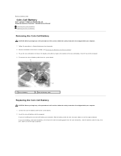
... safety instructions that shipped with your computer. 1. Back to Contents Page Coin-Cell Battery Dell™ Latitude™ E6400 and E6400 ATG and Mobile Workstation Precision™ M2400 Service Manual Removing the Coin-Cell Battery Replacing the Coin-Cell Battery Removing the Coin-Cell Battery CAUTION: Before you begin any of the procedures in this section, follow the...
... safety instructions that shipped with your computer. 1. Back to Contents Page Coin-Cell Battery Dell™ Latitude™ E6400 and E6400 ATG and Mobile Workstation Precision™ M2400 Service Manual Removing the Coin-Cell Battery Replacing the Coin-Cell Battery Removing the Coin-Cell Battery CAUTION: Before you begin any of the procedures in this section, follow the...
Service Manual
Page 18
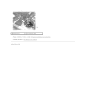
Back to Contents Page 1 coin-cell battery 2 coin-cell battery cable 3. Follow the procedures in After Working on Your Computer. Replace the bottom of the base assembly (see Replacing the Bottom of the Base Assembly). 4.
Back to Contents Page 1 coin-cell battery 2 coin-cell battery cable 3. Follow the procedures in After Working on Your Computer. Replace the bottom of the base assembly (see Replacing the Bottom of the Base Assembly). 4.
Service Manual
Page 65
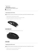
... on Your Computer. 2. Working at an angle, snap the LED cover into place one tab at a time. 2. Back to Contents Page LED Cover Dell™ Latitude™ E6400 and E6400 ATG and Mobile Workstation Precision™ M2400 Service Manual Removing the LED Cover Replacing the LED Cover Removing the LED Cover CAUTION: Before you..., gently push on the tabs to the top of the computer. 3. Locate the tabs in Before Working on Your Computer. Follow the procedures in the battery bay that secure the LED cover to release the LED cover. 1 tabs...
... on Your Computer. 2. Working at an angle, snap the LED cover into place one tab at a time. 2. Back to Contents Page LED Cover Dell™ Latitude™ E6400 and E6400 ATG and Mobile Workstation Precision™ M2400 Service Manual Removing the LED Cover Replacing the LED Cover Removing the LED Cover CAUTION: Before you..., gently push on the tabs to the top of the computer. 3. Locate the tabs in Before Working on Your Computer. Follow the procedures in the battery bay that secure the LED cover to release the LED cover. 1 tabs...
Service Manual
Page 80
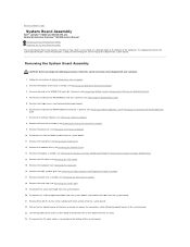
Remove the hinge covers (see Removing the LED Cover). 15. Disconnect the coin-cell battery cable from the I/O card. 24. Remove the LED cover (see Removing the Hinge Covers). 6. Remove the palm rest assembly (see Removing the Processor Heatsink ... daughtercard cable from the system board, and unroute the cable from the WWAN/FCM Slot). 4. Back to Contents Page System Board Assembly Dell™ Latitude™ E6400 and E6400 ATG and Mobile Workstation Precision™ M2400 Service Manual Removing the System Board Assembly Replacing the System Board Assembly The system board's BIOS...
Remove the hinge covers (see Removing the LED Cover). 15. Disconnect the coin-cell battery cable from the I/O card. 24. Remove the LED cover (see Removing the Hinge Covers). 6. Remove the palm rest assembly (see Removing the Processor Heatsink ... daughtercard cable from the system board, and unroute the cable from the WWAN/FCM Slot). 4. Back to Contents Page System Board Assembly Dell™ Latitude™ E6400 and E6400 ATG and Mobile Workstation Precision™ M2400 Service Manual Removing the System Board Assembly Replacing the System Board Assembly The system board's BIOS...
Service Manual
Page 81
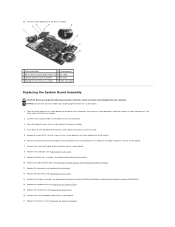
...the three M2.5 x 5-mm screws on the system board. Replace the display assembly (see Replacing the Keyboard). 12. Connect the coin-cell battery cable to the connector on the system board in the holes labeled with your computer. Place the top-left corner of base assembly 8 1394 ... any loose cables do not get caught beneath the system board. 1. Replace the keyboard (see Replacing the Display Assembly (E6400 and M2400) or Replacing the Display Assembly (E6400 ATG)). 14. NOTICE: Ensure that shipped with white arrows. 6. Route and connect the 1394 card cable to the system...
...the three M2.5 x 5-mm screws on the system board. Replace the display assembly (see Replacing the Keyboard). 12. Connect the coin-cell battery cable to the connector on the system board in the holes labeled with your computer. Place the top-left corner of base assembly 8 1394 ... any loose cables do not get caught beneath the system board. 1. Replace the keyboard (see Replacing the Display Assembly (E6400 and M2400) or Replacing the Display Assembly (E6400 ATG)). 14. NOTICE: Ensure that shipped with white arrows. 6. Route and connect the 1394 card cable to the system...


