E-Family Re-Image Guide
Page 16
...o Atmel Trusted Platform Module o STMicroelectronics Trusted Platform Module o Winbond Trusted Platform Module o O2Micro Smart Card Reader o Dell Smart Card Keyboard o UPEK TouchChip Fingerprint Reader o Authentec Fingerprint Reader o Broadcom Unified Security Hub o Vista Storage driver Update (for ...network connectivity: • Intel 825xx Gigabit Platform LAN Network device is available on E-Family - Intel (E4200, E4300, E6400/E6410, E6500...
...o Atmel Trusted Platform Module o STMicroelectronics Trusted Platform Module o Winbond Trusted Platform Module o O2Micro Smart Card Reader o Dell Smart Card Keyboard o UPEK TouchChip Fingerprint Reader o Authentec Fingerprint Reader o Broadcom Unified Security Hub o Vista Storage driver Update (for ...network connectivity: • Intel 825xx Gigabit Platform LAN Network device is available on E-Family - Intel (E4200, E4300, E6400/E6410, E6500...
E-Family Re-Image Guide
Page 17
... management configuring and alerting capabilities: o Battery Status o Power Scheme and Sleep Mode o Display and Devices o Keyboard Backlighting and Hotkeys Customization o Extended Battery Life / All Day Battery Life - For All Day Battery Life feature (ADBL), install the Dell Control Point components offered by installing ALS utility in addition to Vista 32 & 64-Bit...
... management configuring and alerting capabilities: o Battery Status o Power Scheme and Sleep Mode o Display and Devices o Keyboard Backlighting and Hotkeys Customization o Extended Battery Life / All Day Battery Life - For All Day Battery Life feature (ADBL), install the Dell Control Point components offered by installing ALS utility in addition to Vista 32 & 64-Bit...
E-Family Re-Image Guide
Page 26
... Platform Module o Atmel Trusted Platform Module o STMicroelectronics Trusted Platform Module o Winbond Trusted Platform Module o O2Micro Smart Card Reader o Dell Smart Card Keyboard o UPEK TouchChip Fingerprint Reader o Authentec Fingerprint Reader o Broadcom Unified Security Hub o Vista Storage Driver Update (for the correct operation... you need to install the ST Micro Freefall Sensor driver found in the Control Point Security Device Driver pack? The Dell System Software utility provides critical updates and patches for your system. a. After installing the drivers and you need to ...
... Platform Module o Atmel Trusted Platform Module o STMicroelectronics Trusted Platform Module o Winbond Trusted Platform Module o O2Micro Smart Card Reader o Dell Smart Card Keyboard o UPEK TouchChip Fingerprint Reader o Authentec Fingerprint Reader o Broadcom Unified Security Hub o Vista Storage Driver Update (for the correct operation... you need to install the ST Micro Freefall Sensor driver found in the Control Point Security Device Driver pack? The Dell System Software utility provides critical updates and patches for your system. a. After installing the drivers and you need to ...
E-Family Re-Image Guide
Page 28
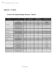
...No Yes N/A Through BIOS Yes N/A Through BIOS Yes N/A Through BIOS Yes N/A Through BIOS Yes N/A No Yes N/A No Yes N/A No Dell Confidential Yes, through BIOS Yes, through on screen display v1.0 Reporting of Ambient Temp log information v1.2 at OS presence (PWS only) ...Installed? E-Family Reimage "How-To" Guide Appendix - Table B1 Category Power Manager Display settings Function Keys Hot Key customizaton Keyboard backlighting Brightness ALS Feature DCP SM Release Version user profiles v1.0 View battery manufacturer info. Fn+F2 to enable Battery ...
...No Yes N/A Through BIOS Yes N/A Through BIOS Yes N/A Through BIOS Yes N/A Through BIOS Yes N/A No Yes N/A No Yes N/A No Dell Confidential Yes, through BIOS Yes, through on screen display v1.0 Reporting of Ambient Temp log information v1.2 at OS presence (PWS only) ...Installed? E-Family Reimage "How-To" Guide Appendix - Table B1 Category Power Manager Display settings Function Keys Hot Key customizaton Keyboard backlighting Brightness ALS Feature DCP SM Release Version user profiles v1.0 View battery manufacturer info. Fn+F2 to enable Battery ...
Setup and Quick Reference Guide
Page 8
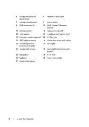
5 display and (optional) touchscreen 6 keyboard status lights 7 volume control buttons 8 power button 9 USB connectors (2) 10 Wi-Fi Catcher™ Network Locator 11 wireless switch 12 audio connectors (2) 13 right speaker ... (SD) memory-card reader 20 touch pad 21 display latch release 22 touch pad buttons/track stick buttons 23 left speaker 24 track stick 25 keyboard 26 device status lights 27 ambient light sensor 8 About Your Computer
5 display and (optional) touchscreen 6 keyboard status lights 7 volume control buttons 8 power button 9 USB connectors (2) 10 Wi-Fi Catcher™ Network Locator 11 wireless switch 12 audio connectors (2) 13 right speaker ... (SD) memory-card reader 20 touch pad 21 display latch release 22 touch pad buttons/track stick buttons 23 left speaker 24 track stick 25 keyboard 26 device status lights 27 ambient light sensor 8 About Your Computer
Setup and Quick Reference Guide
Page 14
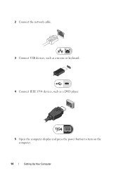
2 Connect the network cable. 3 Connect USB devices, such as a mouse or keyboard. 4 Connect IEEE 1394 devices, such as a DVD player. 5 Open the computer display and press the power button to turn on the computer. 14 Setting Up Your Computer
2 Connect the network cable. 3 Connect USB devices, such as a mouse or keyboard. 4 Connect IEEE 1394 devices, such as a DVD player. 5 Open the computer display and press the power button to turn on the computer. 14 Setting Up Your Computer

Setup and Quick Reference Guide
Page 26
Keyboard Number of keys Layout Size 83 (U.S. and Canada); 84 (Europe); 87 (Japan) QWERTY/AZERTY/Kanji full sized (19-mm key pitch) Touch Pad X/Y position resolution (...
Keyboard Number of keys Layout Size 83 (U.S. and Canada); 84 (Europe); 87 (Japan) QWERTY/AZERTY/Kanji full sized (19-mm key pitch) Touch Pad X/Y position resolution (...
Setup and Quick Reference Guide
Page 31
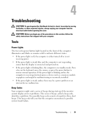
... power. • If the power light is steady blue and the computer is not responding, ensure that the display is connected and powered on the keyboard, move the mouse, or press the power button to resume normal operation. One possible beep code consists of beeps, called a beep code, identifies a problem. Press...
... power. • If the power light is steady blue and the computer is not responding, ensure that the display is connected and powered on the keyboard, move the mouse, or press the power button to resume normal operation. One possible beep code consists of beeps, called a beep code, identifies a problem. Press...
Setup and Quick Reference Guide
Page 35
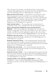
... cannot be defective. Run the Hard Disk Drive tests in the Dell Diagnostics (see "Dell Diagnostics" on page 40). Run the Keyboard Controller test in the Dell Diagnostics (see your Service Manual at support.dell.com), and boot the computer from a CD. Restart the computer...HA R D - Correct the appropriate options in the Dell Diagnostics (see "Dell Diagnostics" on page 40). Run the Keyboard Controller test in the Dell Diagnostics (see "Dell Diagnostics" on page 40). The hard drive may be played (see "Dell Diagnostics" on page 40). Then, shut down the computer...
... cannot be defective. Run the Hard Disk Drive tests in the Dell Diagnostics (see "Dell Diagnostics" on page 40). Run the Keyboard Controller test in the Dell Diagnostics (see your Service Manual at support.dell.com), and boot the computer from a CD. Restart the computer...HA R D - Correct the appropriate options in the Dell Diagnostics (see "Dell Diagnostics" on page 40). Run the Keyboard Controller test in the Dell Diagnostics (see "Dell Diagnostics" on page 40). The hard drive may be played (see "Dell Diagnostics" on page 40). Then, shut down the computer...

Setup and Quick Reference Guide
Page 38
...Dell" on page 65 for assistance). Run the System Set tests in the Dell Diagnostics (see "Dell Diagnostics" on page 40). Run the System Memory tests and the Keyboard Controller test in the Dell Diagnostics (see "Dell... T A C T D E L L TE C H N I L E D - TI M E - If the message reappears, contact Dell (see "Contacting Dell" on page 65 for either the operating system or the program that supports the system configuration settings may be malfunctioning. O F - The keyboard controller may be malfunctioning, or a memory module may require recharging. WA R N I N G : BA T T E R Y I ...
...Dell" on page 65 for assistance). Run the System Set tests in the Dell Diagnostics (see "Dell Diagnostics" on page 40). Run the System Memory tests and the Keyboard Controller test in the Dell Diagnostics (see "Dell... T A C T D E L L TE C H N I L E D - TI M E - If the message reappears, contact Dell (see "Contacting Dell" on page 65 for either the operating system or the program that supports the system configuration settings may be malfunctioning. O F - The keyboard controller may be malfunctioning, or a memory module may require recharging. WA R N I N G : BA T T E R Y I ...

Setup and Quick Reference Guide
Page 39
.... Troubleshooting 39 HARD-DI SK DRIVE FA ILURE - Check cables, swap hard disks, or see "Contacting Dell" on page 65 for assistance. DI SK D R I V E R E A D F AILU RE - KEYBOARD F AILURE - NO BO OT D E V IC E AVAILA BLE - NOTICE - See your Service Manual at support.dell.com). Possible hard drive failure during harddrive start test (see "Contacting...
.... Troubleshooting 39 HARD-DI SK DRIVE FA ILURE - Check cables, swap hard disks, or see "Contacting Dell" on page 65 for assistance. DI SK D R I V E R E A D F AILU RE - KEYBOARD F AILURE - NO BO OT D E V IC E AVAILA BLE - NOTICE - See your Service Manual at support.dell.com). Possible hard drive failure during harddrive start test (see "Contacting...

Setup and Quick Reference Guide
Page 43
...that the display is connected and powered on. • If the display is connected and powered on, see "Beep Codes" on the keyboard, move the mouse, or press the power button to the same electrical outlet Memory Problems CAUTION: Before you are securely connected to the system...). There is securely connected to the system board power connector (see your Service Manual at support.dell.com). • Remove and then reinstall any of interference are: • Power, keyboard, and mouse extension cables • Too many devices connected to the same power strip • Multiple power ...
...that the display is connected and powered on. • If the display is connected and powered on, see "Beep Codes" on the keyboard, move the mouse, or press the power button to the same electrical outlet Memory Problems CAUTION: Before you are securely connected to the system...). There is securely connected to the system board power connector (see your Service Manual at support.dell.com). • Remove and then reinstall any of interference are: • Power, keyboard, and mouse extension cables • Too many devices connected to the same power strip • Multiple power ...
Setup and Quick Reference Guide
Page 44
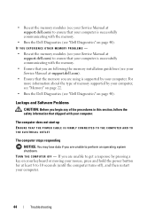
...and Software Problems CAUTION: Before you begin any of memory supported by pressing a key on your keyboard or moving your computer, see "Memory" on page 22. • Run the Dell Diagnostics (see "Dell Diagnostics" on page 40). The computer does not start up ENSURE THAT THE POWER CABLE IS... OUTLET The computer stops responding NOTICE: You may lose data if you are following the memory installation guidelines (see your Service Manual at support.dell.com). • Ensure that shipped with your computer. IF YOU EXPERIENCE OTHER MEMORY PROBLEMS - • Reseat the memory modules (see your...
...and Software Problems CAUTION: Before you begin any of memory supported by pressing a key on your keyboard or moving your computer, see "Memory" on page 22. • Run the Dell Diagnostics (see "Dell Diagnostics" on page 40). The computer does not start up ENSURE THAT THE POWER CABLE IS... OUTLET The computer stops responding NOTICE: You may lose data if you are following the memory installation guidelines (see your Service Manual at support.dell.com). • Ensure that shipped with your computer. IF YOU EXPERIENCE OTHER MEMORY PROBLEMS - • Reseat the memory modules (see your...

Setup and Quick Reference Guide
Page 45
... unable to non-XP operating system environments. 1 Click Start→ All Programs→ Accessories→ Program Compatibility Wizard→ Next. 2 Follow the instructions on your keyboard or moving your computer. A program crashes repeatedly NOTE: Most software includes installation instructions in an environment similar to get a response by pressing a key on the...
... unable to non-XP operating system environments. 1 Click Start→ All Programs→ Accessories→ Program Compatibility Wizard→ Next. 2 Follow the instructions on your keyboard or moving your computer. A program crashes repeatedly NOTE: Most software includes installation instructions in an environment similar to get a response by pressing a key on the...
Setup and Quick Reference Guide
Page 55
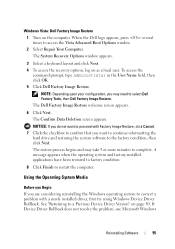
... Click Next. NOTICE: If you do not want to continue reformatting the hard drive and restoring the system software to select Dell Factory Tools, then Dell Factory Image Restore. See "Returning to complete. The restore process begins and may need to the factory condition, then click ...installed applications have been restored to factory condition. 8 Click Finish to restart the computer. The System Recovery Options window appears. 3 Select a keyboard layout and click Next. 4 To access the recovery options, log on the computer. The Confirm Data Deletion screen appears. If Device Driver...
... Click Next. NOTICE: If you do not want to continue reformatting the hard drive and restoring the system software to select Dell Factory Tools, then Dell Factory Image Restore. See "Returning to complete. The restore process begins and may need to the factory condition, then click ...installed applications have been restored to factory condition. 8 Click Finish to restart the computer. The System Recovery Options window appears. 3 Select a keyboard layout and click Next. 4 To access the recovery options, log on the computer. The Confirm Data Deletion screen appears. If Device Driver...

Setup and Quick Reference Guide
Page 63
... and call from a telephone at the computer itself. Before You Call NOTE: Have your Express Service Code ready when you call Dell for your Service Tag (located on the back or bottom of your computer). Ensure that shipped with your call more efficiently. CAUTION... in the documentation that the computer documentation is available. Getting Help 63 The code helps Dell's automated-support telephone system direct your computer. Remember to type some commands at the keyboard, relay detailed information during operations, or try other troubleshooting steps possible only at or near...
... and call from a telephone at the computer itself. Before You Call NOTE: Have your Express Service Code ready when you call Dell for your Service Tag (located on the back or bottom of your computer). Ensure that shipped with your call more efficiently. CAUTION... in the documentation that the computer documentation is available. Getting Help 63 The code helps Dell's automated-support telephone system direct your computer. Remember to type some commands at the keyboard, relay detailed information during operations, or try other troubleshooting steps possible only at or near...
Service Manual
Page 1
...Corporation in the United States and/or other countries. A00 Intel is strictly forbidden. Dell™ Latitude™ E6400 and E6400 ATG and Mobile Workstation Precision™ M2400 Service Manual Troubleshooting Working on Your Computer Base Assembly... Hinge Covers Hard Drive WLAN/WiMax Card WWAN Card WPAN (UWB/BT) Card FCM Fan Processor Heatsink Assembly Processor Module Memory Coin-Cell Battery Modular Drive LED Cover Keyboard...
...Corporation in the United States and/or other countries. A00 Intel is strictly forbidden. Dell™ Latitude™ E6400 and E6400 ATG and Mobile Workstation Precision™ M2400 Service Manual Troubleshooting Working on Your Computer Base Assembly... Hinge Covers Hard Drive WLAN/WiMax Card WWAN Card WPAN (UWB/BT) Card FCM Fan Processor Heatsink Assembly Processor Module Memory Coin-Cell Battery Modular Drive LED Cover Keyboard...
Service Manual
Page 2
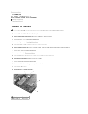
... cage (see Removing the Display Assembly (E6400 and M2400) or Removing the Display Assembly (E6400 ATG)). 7. Remove the two M2 x 3 screws. 14. Remove the modular drive (see Removing the Keyboard). 9. Remove the palm rest assembly (Removing...keyboard (see Removing the Modular Drive). 4. Remove the right speaker grill (see Removing the Bottom of the base assembly (see Removing the Right Speaker Grill/Fingerprint Reader Assembly). 10. Disconnect the 1394 cable from the system board, and unroute the cable. 13. Back to Contents Page 1394 Card Dell™ Latitude™ E6400 and E6400 ATG...
... cage (see Removing the Display Assembly (E6400 and M2400) or Removing the Display Assembly (E6400 ATG)). 7. Remove the two M2 x 3 screws. 14. Remove the modular drive (see Removing the Keyboard). 9. Remove the palm rest assembly (Removing...keyboard (see Removing the Modular Drive). 4. Remove the right speaker grill (see Removing the Bottom of the base assembly (see Removing the Right Speaker Grill/Fingerprint Reader Assembly). 10. Disconnect the 1394 cable from the system board, and unroute the cable. 13. Back to Contents Page 1394 Card Dell™ Latitude™ E6400 and E6400 ATG...
Service Manual
Page 3
.../Fingerprint Reader Assembly). 7. Replace the right speaker grill (see Replacing the Card Cage). 5. Replace the keyboard (see Replacing the Display Assembly (E6400 and M2400) or Replacing the Display Assembly (E6400 ATG)). 10. Replace the display assembly (see Replacing the Keyboard). 8. Replace the heatsink assembly (see Replacing the Hinge Covers). 12. Route and connect the 1394...
.../Fingerprint Reader Assembly). 7. Replace the right speaker grill (see Replacing the Card Cage). 5. Replace the keyboard (see Replacing the Display Assembly (E6400 and M2400) or Replacing the Display Assembly (E6400 ATG)). 10. Replace the display assembly (see Replacing the Keyboard). 8. Replace the heatsink assembly (see Replacing the Hinge Covers). 12. Route and connect the 1394...

Service Manual
Page 5
...Keyboard). 13. Replace the hard drive (see Replacing a WPAN (UWB/BT) Card or Replacing an FCM). Replace the card in the WPAN/UWB/FCM card slot, if applicable (see Replacing the Hard Drive). 14. Remove the display assembly (see Replacing the Display Assembly (E6400 and M2400) or Replacing the Display Assembly (E6400 ATG...)). 12. Replace the display assembly (see Removing the Display Assembly (E6400 and M2400) or Removing the Display Assembly (E6400 ATG)). 11. Remove the LED ...
...Keyboard). 13. Replace the hard drive (see Replacing a WPAN (UWB/BT) Card or Replacing an FCM). Replace the card in the WPAN/UWB/FCM card slot, if applicable (see Replacing the Hard Drive). 14. Remove the display assembly (see Replacing the Display Assembly (E6400 and M2400) or Replacing the Display Assembly (E6400 ATG...)). 12. Replace the display assembly (see Removing the Display Assembly (E6400 and M2400) or Removing the Display Assembly (E6400 ATG)). 11. Remove the LED ...


