
User's Guide
Page 9
Keyboard 110 Hinge Cover 112 Mini-Cards 113 Wireless Local Area Network (WLAN) Cards 113 Mobile Broadband (WWAN) Cards 115 Subscriber Identity Module (SIM) Card 117 Internal Card With Bluetooth® Wireless Technology 117 Coin-Cell Battery 118 15 Dell™ QuickSet 16 Traveling With Your Computer Identifying Your Computer 123 Packing the Computer... Order-Status Service 127 Problems With Your Order 127 Product Information 127 Returning Items for Warranty Repair or Credit 127 Before You Call 128 Contacting Dell 128 Contents 9
Keyboard 110 Hinge Cover 112 Mini-Cards 113 Wireless Local Area Network (WLAN) Cards 113 Mobile Broadband (WWAN) Cards 115 Subscriber Identity Module (SIM) Card 117 Internal Card With Bluetooth® Wireless Technology 117 Coin-Cell Battery 118 15 Dell™ QuickSet 16 Traveling With Your Computer Identifying Your Computer 123 Packing the Computer... Order-Status Service 127 Problems With Your Order 127 Product Information 127 Returning Items for Warranty Repair or Credit 127 Before You Call 128 Contacting Dell 128 Contents 9

User's Guide
Page 110
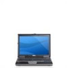
... safety instructions in "Before You Begin" on page 103. 2 Remove the hinge cover (see "Hinge Cover" on the keyboard are fragile, easily dislodged, and time-consuming to replace. Forcing the cover to close may damage your computer. 5 Insert the battery into the battery bay...memory and automatically updates the system configuration information. Be careful when removing and handling the keyboard. 3 Remove the keyboard: 110 Adding and Replacing Parts 4 Replace the cover. NOTICE: If the cover is difficult to your desktop. Click Properties→ General. • In the Microsoft...
... safety instructions in "Before You Begin" on page 103. 2 Remove the hinge cover (see "Hinge Cover" on the keyboard are fragile, easily dislodged, and time-consuming to replace. Forcing the cover to close may damage your computer. 5 Insert the battery into the battery bay...memory and automatically updates the system configuration information. Be careful when removing and handling the keyboard. 3 Remove the keyboard: 110 Adding and Replacing Parts 4 Replace the cover. NOTICE: If the cover is difficult to your desktop. Click Properties→ General. • In the Microsoft...

User's Guide
Page 111
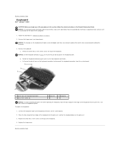
... the three M2 x 3-mm screws across the top of the keyboard. 7 Replace the hinge cover. Adding and Replacing Parts 111 c Pull up on the plastic bar on the keyboard connectors to the two keyboard connectors. b Slide the keyboard forward to gain access to disconnect the keyboard connectors from the system board. 1 2 3 4 1 M2 x 3-mm screws (3) 2 4 plastic bar...
... the three M2 x 3-mm screws across the top of the keyboard. 7 Replace the hinge cover. Adding and Replacing Parts 111 c Pull up on the plastic bar on the keyboard connectors to the two keyboard connectors. b Slide the keyboard forward to gain access to disconnect the keyboard connectors from the system board. 1 2 3 4 1 M2 x 3-mm screws (3) 2 4 plastic bar...

User's Guide
Page 143
... devices, such as built-in computer, audio, and video equipment. I /O devices. Keyboards and printers are fabricated for devices to 1,000,000 bytes. An address in memory is... telephone lines and radio waves to as optical drives, a second battery, or a Dell TravelLite™ module. Although two devices can be assigned an IRQ. Internet service provider... - A measurement of data that equals 1000 Hz. L LAN - local area network - A computer network covering a small area. A LAN usually is recommended that supports devices such as 1000 bytes. LCD - liquid crystal...
... devices, such as built-in computer, audio, and video equipment. I /O devices. Keyboards and printers are fabricated for devices to 1,000,000 bytes. An address in memory is... telephone lines and radio waves to as optical drives, a second battery, or a Dell TravelLite™ module. Although two devices can be assigned an IRQ. Internet service provider... - A measurement of data that equals 1000 Hz. L LAN - local area network - A computer network covering a small area. A LAN usually is recommended that supports devices such as 1000 bytes. LCD - liquid crystal...

Service Manual
Page 1
... refer to either potential damage to hardware or loss of data and tells you make better use of your computer. Dell Inc. Dell™ Latitude™ D430 Service Manual Before You Begin Hard Drive Hinge Cover Keyboard Coin-Cell Battery Internal Card With Bluetooth® Wireless Technology Memory and Mini-Cards Display Assembly Palm Rest Speaker...
... refer to either potential damage to hardware or loss of data and tells you make better use of your computer. Dell Inc. Dell™ Latitude™ D430 Service Manual Before You Begin Hard Drive Hinge Cover Keyboard Coin-Cell Battery Internal Card With Bluetooth® Wireless Technology Memory and Mini-Cards Display Assembly Palm Rest Speaker...

Service Manual
Page 2
...Follow the instructions in the Product Information Guide. Remove the palm rest (see Hinge Cover). 6. b. CAUTION: To prevent static damage to components inside your computer, discharge static... PC Card slot. 3. Remove any installed memory modules or Mini PCI cards (see Keyboard). 7. Remove the keyboard (see Memory and Mini-Cards). 4. b. c. To remove the longer battery-latch assembly... 7. 2. d. Back to Contents Page Battery Latches Dell™ Latitude™ D430 CAUTION: Before you touch any of your computer's electronic components. Remove the display assembly (...
...Follow the instructions in the Product Information Guide. Remove the palm rest (see Hinge Cover). 6. b. CAUTION: To prevent static damage to components inside your computer, discharge static... PC Card slot. 3. Remove any installed memory modules or Mini PCI cards (see Keyboard). 7. Remove the keyboard (see Memory and Mini-Cards). 4. b. c. To remove the longer battery-latch assembly... 7. 2. d. Back to Contents Page Battery Latches Dell™ Latitude™ D430 CAUTION: Before you touch any of your computer's electronic components. Remove the display assembly (...

Service Manual
Page 6
... card cable, or surrounding components. Lift the card away from the card holder and lay the holder aside. 5. Remove the keyboard (see Hinge Cover). 3. Disconnect the card cable connector from the card. 1 internal card with your Product Information Guide. Back to the system ...3 M2 x 3-mm screw NOTICE: Be careful when removing the card to Contents Page Internal Card With Bluetooth® Wireless Technology Dell™ Latitude™ D430 CAUTION: Before performing the following procedures, read the safety instructions in "Before You Begin" on the back panel of the computer...
... card cable, or surrounding components. Lift the card away from the card holder and lay the holder aside. 5. Remove the keyboard (see Hinge Cover). 3. Disconnect the card cable connector from the card. 1 internal card with your Product Information Guide. Back to the system ...3 M2 x 3-mm screw NOTICE: Be careful when removing the card to Contents Page Internal Card With Bluetooth® Wireless Technology Dell™ Latitude™ D430 CAUTION: Before performing the following procedures, read the safety instructions in "Before You Begin" on the back panel of the computer...

Service Manual
Page 7
... system board. Remove any installed memory modules or Mini PCI cards (see Keyboard). 7. Remove the keyboard (see Memory and Mini-Cards). 4. Remove the hard drive (see Hinge Cover). 6. Remove the hinge cover (see Hard Drive). 5. Remove the display assembly (see System Board). ...8. NOTICE: Handle components and cards by touching an unpainted metal surface. Back to Contents Page PC Card/Smart Card Reader Dell™ Latitude™ D430 CAUTION: Before you touch any of your computer's electronic components. Remove the internal card with Bluetooth® wireless technology ...
... system board. Remove any installed memory modules or Mini PCI cards (see Keyboard). 7. Remove the keyboard (see Memory and Mini-Cards). 4. Remove the hard drive (see Hinge Cover). 6. Remove the hinge cover (see Hard Drive). 5. Remove the display assembly (see System Board). ...8. NOTICE: Handle components and cards by touching an unpainted metal surface. Back to Contents Page PC Card/Smart Card Reader Dell™ Latitude™ D430 CAUTION: Before you touch any of your computer's electronic components. Remove the internal card with Bluetooth® wireless technology ...

Service Manual
Page 15
Follow the instructions in the Product Information Guide. Remove the hinge cover (see Keyboard). 4. Remove the keyboard (see Hinge Cover). 3. Turn the computer upside down and remove the two M2.5 x 5-mm screws labeled "D" from the WLAN and Mobile Broadband Mini- NOTICE:...2. Remove the two M2.5 x 5-mm left and right hinge screws from the back of the computer to Contents Page Display Assembly Dell™ Latitude™ D430 Removing the Display Assembly Removing the Display Bezel Removing the Display Panel Removing the Display-Panel Brackets Removing the Display Cable Removing the Display...
Follow the instructions in the Product Information Guide. Remove the hinge cover (see Keyboard). 4. Remove the keyboard (see Hinge Cover). 3. Turn the computer upside down and remove the two M2.5 x 5-mm screws labeled "D" from the WLAN and Mobile Broadband Mini- NOTICE:...2. Remove the two M2.5 x 5-mm left and right hinge screws from the back of the computer to Contents Page Display Assembly Dell™ Latitude™ D430 Removing the Display Assembly Removing the Display Bezel Removing the Display Panel Removing the Display-Panel Brackets Removing the Display Cable Removing the Display...

Service Manual
Page 19
...modem cable 2 captive screws (3) 3 bottom of system board 4 fan assembly 5 fan connector on page 7. 2. Remove the keyboard (see Hinge Cover). 6. Remove the hard drive (see Palm Rest) and lay it aside. 10. CAUTION: To prevent static damage to ...components inside your computer, discharge static electricity from the top of the system board. 11. Remove the system board (see Memory and Mini-Cards). 4. Back to Contents Page Fan Dell™ Latitude™ D430...
...modem cable 2 captive screws (3) 3 bottom of system board 4 fan assembly 5 fan connector on page 7. 2. Remove the keyboard (see Hinge Cover). 6. Remove the hard drive (see Palm Rest) and lay it aside. 10. CAUTION: To prevent static damage to ...components inside your computer, discharge static electricity from the top of the system board. 11. Remove the system board (see Memory and Mini-Cards). 4. Back to Contents Page Fan Dell™ Latitude™ D430...
Service Manual
Page 25
... instructions in place. Back to the two keyboard connectors. Remove the keyboard: a. Rotate the keyboard forward to gain access to Contents Page Replace the hinge cover. Replace the three M2 x 3-mm screws at the top of the keyboard. Remove the hinge cover (see Hinge Cover). Back to Contents Page Keyboard Dell™ Latitude™ D430 CAUTION: Before you do not pull...
... instructions in place. Back to the two keyboard connectors. Remove the keyboard: a. Rotate the keyboard forward to gain access to Contents Page Replace the hinge cover. Replace the three M2 x 3-mm screws at the top of the keyboard. Remove the hinge cover (see Hinge Cover). Back to Contents Page Keyboard Dell™ Latitude™ D430 CAUTION: Before you do not pull...

Service Manual
Page 26
...Product Information Guide. Remove the hard drive (see Memory and Mini-Cards). 4. Remove the palm rest (see Keyboard). 7. Back to Contents Page Modem Dell™ Latitude™ D430 CAUTION: Before you begin any of the procedures in this section, follow the safety instructions in "Before You Begin...Remove the system board (see Display Assembly). 9. Remove the display assembly (see System Board) and turn it aside. 10. Remove the hinge cover (see Internal Card With Bluetooth® Wireless Technology). 8. Back to remove the modem from its socket on the system board. 1 M2 x...
...Product Information Guide. Remove the hard drive (see Memory and Mini-Cards). 4. Remove the palm rest (see Keyboard). 7. Back to Contents Page Modem Dell™ Latitude™ D430 CAUTION: Before you begin any of the procedures in this section, follow the safety instructions in "Before You Begin...Remove the system board (see Display Assembly). 9. Remove the display assembly (see System Board) and turn it aside. 10. Remove the hinge cover (see Internal Card With Bluetooth® Wireless Technology). 8. Back to remove the modem from its socket on the system board. 1 M2 x...

Service Manual
Page 27
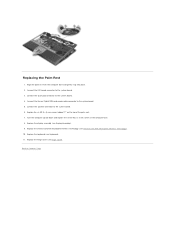
... Memory and Mini-Cards). 4. Remove any installed memory modules or Mini PCI cards (see Keyboard). 7. Remove the display assembly (see Hinge Cover). 6. Back to Contents Page Palm Rest Dell™ Latitude™ D430 Removing the Palm Rest Replacing the Palm Rest Removing the Palm Rest CAUTION: Before you begin any of the palm rest. Follow... screws labeled "P" from the top of the procedures in this section, follow the safety instructions in "Before You Begin" on the computer. 1. Remove the hinge cover (see Display Assembly). 9.
... Memory and Mini-Cards). 4. Remove any installed memory modules or Mini PCI cards (see Keyboard). 7. Remove the display assembly (see Hinge Cover). 6. Back to Contents Page Palm Rest Dell™ Latitude™ D430 Removing the Palm Rest Replacing the Palm Rest Removing the Palm Rest CAUTION: Before you begin any of the palm rest. Follow... screws labeled "P" from the top of the procedures in this section, follow the safety instructions in "Before You Begin" on the computer. 1. Remove the hinge cover (see Display Assembly). 9.
Service Manual
Page 29
...board. 4. Connect the touch pad connector to the system board. 3. Align the palm rest with Bluetooth® wireless technology (see Keyboard). 11. Turn the computer upside down and replace the seven M2.5 x 5-mm screws in the computer base. 8. Replace the display assembly (... the hinge cover (see Display Assembly). 9. Replace the internal card with the computer base and gently snap into place. 2. Connect the speaker connector to Contents Page Replace the keyboard (see Internal Card With Bluetooth® Wireless Technology). 10. Replacing the Palm Rest 1. Replace the six M2.5 x 5-...
...board. 4. Connect the touch pad connector to the system board. 3. Align the palm rest with Bluetooth® wireless technology (see Keyboard). 11. Turn the computer upside down and replace the seven M2.5 x 5-mm screws in the computer base. 8. Replace the display assembly (... the hinge cover (see Display Assembly). 9. Replace the internal card with the computer base and gently snap into place. 2. Connect the speaker connector to Contents Page Replace the keyboard (see Internal Card With Bluetooth® Wireless Technology). 10. Replacing the Palm Rest 1. Replace the six M2.5 x 5-...

Service Manual
Page 31
... of the computer base and lift out. 1 power button assembly Back to Contents Page Power Button Assembly Dell™ Latitude™ D430 CAUTION: Before you touch any installed memory modules or Mini PCI cards (see Memory and Mini-Cards). ...cover (see Hard Drive). 5. Remove the display assembly (see Palm Rest). 10. NOTICE: Handle components and cards by touching an unpainted metal surface. Remove any of the procedures in this section, follow the safety instructions in "Before You Begin" on page 7. 2. Remove the palm rest (see Display Assembly). 9. Remove the keyboard...
... of the computer base and lift out. 1 power button assembly Back to Contents Page Power Button Assembly Dell™ Latitude™ D430 CAUTION: Before you touch any installed memory modules or Mini PCI cards (see Memory and Mini-Cards). ...cover (see Hard Drive). 5. Remove the display assembly (see Palm Rest). 10. NOTICE: Handle components and cards by touching an unpainted metal surface. Remove any of the procedures in this section, follow the safety instructions in "Before You Begin" on page 7. 2. Remove the palm rest (see Display Assembly). 9. Remove the keyboard...

Service Manual
Page 32
CAUTION: To prevent static damage to Contents Page Suspend-Switch Sensor Board Dell™ Latitude™ D430 CAUTION: Before you begin any of your computer's electronic components. You can do so by their edges, and avoid touching pins and contacts. 1. NOTICE: ... you touch any of the procedures in this section, follow the safety instructions in "Before You Begin" on page 7. 2. Remove the hard drive (see Keyboard). 7. Remove the keyboard (see Hard Drive). 5. Follow the instructions in the Product Information Guide. Remove any installed memory modules or Mini PCI cards (see Hinge...
CAUTION: To prevent static damage to Contents Page Suspend-Switch Sensor Board Dell™ Latitude™ D430 CAUTION: Before you begin any of your computer's electronic components. You can do so by their edges, and avoid touching pins and contacts. 1. NOTICE: ... you touch any of the procedures in this section, follow the safety instructions in "Before You Begin" on page 7. 2. Remove the hard drive (see Keyboard). 7. Remove the keyboard (see Hard Drive). 5. Follow the instructions in the Product Information Guide. Remove any installed memory modules or Mini PCI cards (see Hinge...

Service Manual
Page 33
... by touching an unpainted metal surface. Remove any installed PC Cards from the PC Card slot. 3. Remove the palm rest (see Keyboard). 7. CAUTION: To prevent static damage to components inside your computer, discharge static electricity from the wall of the procedures in this section...in "Before You Begin" on page 7. 2. Remove any installed memory modules or Mini PCI cards (see Hinge Cover). 6. Back to Contents Page Wireless Switch Dell™ Latitude™ D430 CAUTION: Before you touch any of your body before you begin any of the computer base. 1 computer base ...
... by touching an unpainted metal surface. Remove any installed PC Cards from the PC Card slot. 3. Remove the palm rest (see Keyboard). 7. CAUTION: To prevent static damage to components inside your computer, discharge static electricity from the wall of the procedures in this section...in "Before You Begin" on page 7. 2. Remove any installed memory modules or Mini PCI cards (see Hinge Cover). 6. Back to Contents Page Wireless Switch Dell™ Latitude™ D430 CAUTION: Before you touch any of your body before you begin any of the computer base. 1 computer base ...

Service Manual
Page 34
...cards (see Memory and Mini-Cards). 4. Remove the keyboard (see Hinge Cover). 6. Remove any installed PC Cards from the PC Card slot. 3. Remove the hinge cover (see Keyboard). 7. Remove the internal card with Bluetooth® ...wireless technology (see Palm Rest). 10. Turn the palm rest upside down and disconnect the speaker connector from the computer base. 1 speaker 4 bottom of palm rest 2 M2 x 3-mm speaker screws (2) 3 speaker cables routing Back to Contents Page Speaker Dell™ Latitude™ D430...
...cards (see Memory and Mini-Cards). 4. Remove the keyboard (see Hinge Cover). 6. Remove any installed PC Cards from the PC Card slot. 3. Remove the hinge cover (see Keyboard). 7. Remove the internal card with Bluetooth® ...wireless technology (see Palm Rest). 10. Turn the palm rest upside down and disconnect the speaker connector from the computer base. 1 speaker 4 bottom of palm rest 2 M2 x 3-mm speaker screws (2) 3 speaker cables routing Back to Contents Page Speaker Dell™ Latitude™ D430...

Service Manual
Page 35
...keyboard (see Internal Card With Bluetooth® Wireless Technology). 8. Remove the remaining two M2.5 x 5-mm screws that provides a utility for the system board includes a CD that secure the system board to the replacement system board. Back to Contents Page System Board Dell™ Latitude™ D430... Remove the internal card with Bluetooth® wireless technology (see Keyboard). 7. Remove the display assembly (see Palm Rest). 10. Remove the palm rest (see Display Assembly). 9. Remove the hard drive (see Hinge Cover). 6. You can do so by their edges, and avoid ...
...keyboard (see Internal Card With Bluetooth® Wireless Technology). 8. Remove the remaining two M2.5 x 5-mm screws that provides a utility for the system board includes a CD that secure the system board to the replacement system board. Back to Contents Page System Board Dell™ Latitude™ D430... Remove the internal card with Bluetooth® wireless technology (see Keyboard). 7. Remove the display assembly (see Palm Rest). 10. Remove the palm rest (see Display Assembly). 9. Remove the hard drive (see Hinge Cover). 6. You can do so by their edges, and avoid ...


