
Service Manual
Page 10
...-head screwdriver Small flat-blade screwdriver Small plastic scribe Microprocessor extractor 1. Also disconnect any work in the modular device bay. 2 Dell Latitude CPt V/CPt S Series and CPx H/CPx J Series Service Manual If you cannot shut down the computer using the computer's operating system, ...computer. 5. Disconnect the computer and any attached peripherals. The procedures in suspend-to reduce the potential for 4 seconds. 3. NOTE: Make sure the computer is docked in a C/Dock Family Expansion Station or C/Port Family Advanced Port Replicator (APR), undock the computer. ...
...-head screwdriver Small flat-blade screwdriver Small plastic scribe Microprocessor extractor 1. Also disconnect any work in the modular device bay. 2 Dell Latitude CPt V/CPt S Series and CPx H/CPx J Series Service Manual If you cannot shut down the computer using the computer's operating system, ...computer. 5. Disconnect the computer and any attached peripherals. The procedures in suspend-to reduce the potential for 4 seconds. 3. NOTE: Make sure the computer is docked in a C/Dock Family Expansion Station or C/Port Family Advanced Port Replicator (APR), undock the computer. ...
Service Manual
Page 13
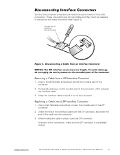
support.dell.com Dell Latitude CPt V/CPt S Series and CPx H/CPx J Series Service Manual 5 Push gently sideways on the movable part of the connector until it out of the connector. 1. These connectors ... (ZIF) connectors. movable part of the cable into the connector. 3. Grasp the interface cable and pull it releases the interface cable. 3. To ensure a firm connection, make sure the ZIF connector is completely closed. Orient the end of the interface cable with the ZIF connector, and insert the end of connector (do...
support.dell.com Dell Latitude CPt V/CPt S Series and CPx H/CPx J Series Service Manual 5 Push gently sideways on the movable part of the connector until it out of the connector. 1. These connectors ... (ZIF) connectors. movable part of the cable into the connector. 3. Grasp the interface cable and pull it releases the interface cable. 3. To ensure a firm connection, make sure the ZIF connector is completely closed. Orient the end of the interface cable with the ZIF connector, and insert the end of connector (do...

Service Manual
Page 32
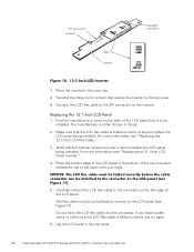
... the panel with your hand. 2. Do not force the LCD flex cable into the connector. Reinstall the six 3-mm screws securing the LCD panel to make sure the LCD flex cable is aligned correctly and try again. 3. Lay the LCD panel in the display. Place the bottom edge of the LCD... top cover and elevate the top of the LCD panel. Secure the right side first. 1. If you have trouble, check to the top cover. 24 Dell Latitude CPt V/CPt S Series and CPx H/CPx J Series Service Manual
... the panel with your hand. 2. Do not force the LCD flex cable into the connector. Reinstall the six 3-mm screws securing the LCD panel to make sure the LCD flex cable is aligned correctly and try again. 3. Lay the LCD panel in the display. Place the bottom edge of the LCD... top cover and elevate the top of the LCD panel. Secure the right side first. 1. If you have trouble, check to the top cover. 24 Dell Latitude CPt V/CPt S Series and CPx H/CPx J Series Service Manual

Service Manual
Page 35
... either panel by making one fold to panel LCD manufacturer name Fold for a Torisan LCD Panel crease (on the inverter shield for a Sharp LCD Panel curled back to connect to the cable. If you are identical on the cable (see Figure 18). Fold for more information. support.dell.com Dell Latitude CPt V/CPt S Series and CPx...
... either panel by making one fold to panel LCD manufacturer name Fold for a Torisan LCD Panel crease (on the inverter shield for a Sharp LCD Panel curled back to connect to the cable. If you are identical on the cable (see Figure 18). Fold for more information. support.dell.com Dell Latitude CPt V/CPt S Series and CPx...
Service Manual
Page 36
The manufacturer is folded correctly and try again. 6. Make sure that is folded correctly to accommodate the LCD panel being installed. Lay the LCD panel in the cover top. 4. Place the inverter in the top cover. 28 Dell Latitude CPt V/CPt S Series and CPx H/CPx J Series Service Manual Find the manufacturer's name on the back of...
The manufacturer is folded correctly and try again. 6. Make sure that is folded correctly to accommodate the LCD panel being installed. Lay the LCD panel in the cover top. 4. Place the inverter in the top cover. 28 Dell Latitude CPt V/CPt S Series and CPx H/CPx J Series Service Manual Find the manufacturer's name on the back of...
Service Manual
Page 46
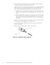
... steps 6 through 8 for the latch on the inside of the case. Snap in the new latch button from the case: a. bumps (2) wear ribs (2) 38 Dell Latitude CPt V/CPt S Series and CPx H/CPx J Series Service Manual Ensure that the slider is inserted in the module latch. 8. Ensure that the surface with the two bumps...latch moves smoothly and freely when pushed and released. 9. 6. If the module latch assembly does come loose from the bottom of the base, making certain its snap tabs are fully engaged in its respective hole, that the side of the latch with the wear ribs is facing the back...
... steps 6 through 8 for the latch on the inside of the case. Snap in the new latch button from the case: a. bumps (2) wear ribs (2) 38 Dell Latitude CPt V/CPt S Series and CPx H/CPx J Series Service Manual Ensure that the slider is inserted in the module latch. 8. Ensure that the surface with the two bumps...latch moves smoothly and freely when pushed and released. 9. 6. If the module latch assembly does come loose from the bottom of the base, making certain its snap tabs are fully engaged in its respective hole, that the side of the latch with the wear ribs is facing the back...


