
Service Manual
Page 5
... Parts and Assemblies 6 Removing and Replacing Field-Replaceable Parts and Assemblies 10 Hard-Disk Drive Assembly 11 Removing the Hard-Disk Drive Assembly 11 Replacing the Hard-Disk Drive Assembly 11 Modular Bay Devices (Diskette Drive, CD-ROM Drive, DVD-ROM Drive, CD-RW Drive, SuperDisk LS-120 Drive, Battery, or Travel Module) . . . . 12 Memory Module Cover 12 Removing the Memory...
... Parts and Assemblies 6 Removing and Replacing Field-Replaceable Parts and Assemblies 10 Hard-Disk Drive Assembly 11 Removing the Hard-Disk Drive Assembly 11 Replacing the Hard-Disk Drive Assembly 11 Modular Bay Devices (Diskette Drive, CD-ROM Drive, DVD-ROM Drive, CD-RW Drive, SuperDisk LS-120 Drive, Battery, or Travel Module) . . . . 12 Memory Module Cover 12 Removing the Memory...
Service Manual
Page 6
.... Figure 9. Figure 11. Figure 19. Figure 2. Figure 5. Computer Orientation 1 Main Battery Removal 3 Screw Identification 3 Disconnecting a Cable from an Interface Connector 5 Exploded View-Computer 10 Hard-Disk Drive Assembly Removal 11 Modular Bay Device Removal 12 Memory Module Removal 13 Removing the Keyboard Assembly Screws 14 Keyboard Assembly Removal 15 Keyboard and Track...
.... Figure 9. Figure 11. Figure 19. Figure 2. Figure 5. Computer Orientation 1 Main Battery Removal 3 Screw Identification 3 Disconnecting a Cable from an Interface Connector 5 Exploded View-Computer 10 Hard-Disk Drive Assembly Removal 11 Modular Bay Device Removal 12 Memory Module Removal 13 Removing the Keyboard Assembly Screws 14 Keyboard Assembly Removal 15 Keyboard and Track...
Service Manual
Page 12
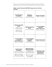
... a tool to your system) Thermal Cooling Assembly and Exhaust Fan: M2.5 x 4 (2 each ) (may not apply to lay out and keep track of the component screws. Hard-Disk Drive Assembly: M3.0 x 5 (1 each) Keyboard Assembly: M2.5 x 10 (7 each) Display Assembly: M2.5 x 4 (3 each) Display Assembly Bezel: Rubber Screw Covers (4 each) ...x 4 (2 each) (w/o modem assembly) M2.5 x 4 (1 each) M2.5 x 10 (1 each) (w/ modem assembly) Microprocessor Shield Assembly: 3 captive and 2 removable screws M2.0 x 3 (2 each) M2.5 x 4 (1 each ) 4 Dell Latitude CPt V/CPt S Series and CPx H/CPx J Series Service Manual
... a tool to your system) Thermal Cooling Assembly and Exhaust Fan: M2.5 x 4 (2 each ) (may not apply to lay out and keep track of the component screws. Hard-Disk Drive Assembly: M3.0 x 5 (1 each) Keyboard Assembly: M2.5 x 10 (7 each) Display Assembly: M2.5 x 4 (3 each) Display Assembly Bezel: Rubber Screw Covers (4 each) ...x 4 (2 each) (w/o modem assembly) M2.5 x 4 (1 each) M2.5 x 10 (1 each) (w/ modem assembly) Microprocessor Shield Assembly: 3 captive and 2 removable screws M2.0 x 3 (2 each) M2.5 x 4 (1 each ) 4 Dell Latitude CPt V/CPt S Series and CPx H/CPx J Series Service Manual
Service Manual
Page 14
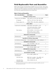
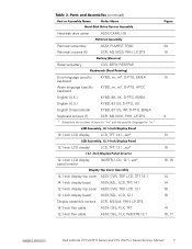
Table 2 lists the parts and assemblies available for the manufacturer's name. 6 Dell Latitude CPt V/CPt S Series and CPx H/CPx J Series Service Manual CUS, ADPT, AC, EXT, 20V, 70W, NBK ADPT, AC, EXT, 20V, 70W, 3W, BA CORD, PWR, ... 7 CD-RW ROM drive CUS, CD-RW, 650M, I, zzz* 7 DVD-ROM drive SUBASSY, DVD, MPEGII, TSHBA 7 Hard-disk drive, HD, xxxxGB, yyMM, zzz* 6 subassembly Hard-disk drive MOD, HD, xxxxGB, I, F2, yyMM, zzz* CUS, HD xxxxGB, I, yyMM, zzz* Hard-disk drive interface board PWA, INTERCON, HD * Substitute the drive capacity for xxxxGB, the drive height for yyMM, and...
Table 2 lists the parts and assemblies available for the manufacturer's name. 6 Dell Latitude CPt V/CPt S Series and CPx H/CPx J Series Service Manual CUS, ADPT, AC, EXT, 20V, 70W, NBK ADPT, AC, EXT, 20V, 70W, 3W, BA CORD, PWR, ... 7 CD-RW ROM drive CUS, CD-RW, 650M, I, zzz* 7 DVD-ROM drive SUBASSY, DVD, MPEGII, TSHBA 7 Hard-disk drive, HD, xxxxGB, yyMM, zzz* 6 subassembly Hard-disk drive MOD, HD, xxxxGB, I, F2, yyMM, zzz* CUS, HD xxxxGB, I, yyMM, zzz* Hard-disk drive interface board PWA, INTERCON, HD * Substitute the drive capacity for xxxxGB, the drive height for yyMM, and...
Service Manual
Page 15
Hard-disk drive carrier ASSY, CARR, HD Palmrest assembly ASSY, PLMRST, TPAD 20 Palmrest screws (5) SCR, M2.5X20, PHH, LP, ZPS 19 Reserve battery CUS, BTRY, RESERVE Euro-... 14.1-inch flex cable ASSY, CBL, FLX, TFT 12.1-inch flex cable ASSY, CBL, FLX, W/EXTN,12.1 14 14 16 16 14 16, 17 support.dell.com Dell Latitude CPt V/CPt S Series and CPx H/CPx J Series Service Manual 7
Hard-disk drive carrier ASSY, CARR, HD Palmrest assembly ASSY, PLMRST, TPAD 20 Palmrest screws (5) SCR, M2.5X20, PHH, LP, ZPS 19 Reserve battery CUS, BTRY, RESERVE Euro-... 14.1-inch flex cable ASSY, CBL, FLX, TFT 12.1-inch flex cable ASSY, CBL, FLX, W/EXTN,12.1 14 14 16 16 14 16, 17 support.dell.com Dell Latitude CPt V/CPt S Series and CPx H/CPx J Series Service Manual 7
Service Manual
Page 18
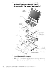
display assembly keyboard palmrest assembly hard-disk drive internal modem (may not apply to your system) system board main battery case plug for modem bottom case assembly modular bay device The following subsections provide instructions for removing and replacing field-replaceable parts and assemblies. 10 Dell Latitude CPt V/CPt S Series and CPx H/CPx J Series Service Manual
display assembly keyboard palmrest assembly hard-disk drive internal modem (may not apply to your system) system board main battery case plug for modem bottom case assembly modular bay device The following subsections provide instructions for removing and replacing field-replaceable parts and assemblies. 10 Dell Latitude CPt V/CPt S Series and CPx H/CPx J Series Service Manual
Service Manual
Page 19
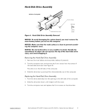
... the computer. 2. Push the drive assembly into the opening on the drive door. Slide the drive door down until it aligns with the cover. 3. support.dell.com Dell Latitude CPt V/CPt S Series and CPx H/CPx J Series Service Manual 11 Turn the computer over , and remove the 5-mm screw from the center of the hard-disk drive door (see Figure 6). Turn...
... the computer. 2. Push the drive assembly into the opening on the drive door. Slide the drive door down until it aligns with the cover. 3. support.dell.com Dell Latitude CPt V/CPt S Series and CPx H/CPx J Series Service Manual 11 Turn the computer over , and remove the 5-mm screw from the center of the hard-disk drive door (see Figure 6). Turn...
Service Manual
Page 42
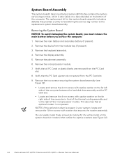
... cooling assembly and to the replacement system board assembly. 1. Remove the two screws securing the system board assembly (see Figure 22). 34 Dell Latitude CPt V/CPt S Series and CPx H/CPx J Series Service Manual You can easily locate these screws by looking for transferring the service tag number to ...system board assembly includes a diskette that provides a utility for the white marks on the far left side of the computer between the hard-disk drive assembly and the PC Card slot. Verify that the PC Card ejectors do not extend from the modular bay (if present). 3. Remove...
... cooling assembly and to the replacement system board assembly. 1. Remove the two screws securing the system board assembly (see Figure 22). 34 Dell Latitude CPt V/CPt S Series and CPx H/CPx J Series Service Manual You can easily locate these screws by looking for transferring the service tag number to ...system board assembly includes a diskette that provides a utility for the white marks on the far left side of the computer between the hard-disk drive assembly and the PC Card slot. Verify that the PC Card ejectors do not extend from the modular bay (if present). 3. Remove...
Service Manual
Page 48
hard-disk drive assembly removal, 11 reserve battery removal, 32 inverter, 12.1-inch LCD panel removal, 26 replacement, 27 keyboard assembly removal, 15 memory module removal, 13 memory ... bay devices removal, 12 module latch assemblies removal, 37 screw identification and tightening, 3 sockets memory module, 13 SuperDisk LS-120 drive removal, 12 system board assembly removal, 18 thermal cooling assembly removal, 36 tools, 2 travel module removal, 12 ZIF connectors, 5 palmrest assembly removal, 30 2 Dell Latitude CPt V/CPt S Series and CPx H/Cpx J Series Service Manual
hard-disk drive assembly removal, 11 reserve battery removal, 32 inverter, 12.1-inch LCD panel removal, 26 replacement, 27 keyboard assembly removal, 15 memory module removal, 13 memory ... bay devices removal, 12 module latch assemblies removal, 37 screw identification and tightening, 3 sockets memory module, 13 SuperDisk LS-120 drive removal, 12 system board assembly removal, 18 thermal cooling assembly removal, 36 tools, 2 travel module removal, 12 ZIF connectors, 5 palmrest assembly removal, 30 2 Dell Latitude CPt V/CPt S Series and CPx H/Cpx J Series Service Manual
System Information Guide (multilanguage: English, Japanese, Chinese-Traditional, Chinese-Simplified, Korean, Thai)
Page 5
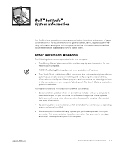
...the latest information. • Operating system documentation, which is located on your Dell computer. Preliminary 1/25/00 Dell Latitude System Information 1-1 (Rev. 11/3/98) FILE LOCATION: \\Pd-xuzhan\d\FrameMaker\Dell\sndmm003\en\999CCA00en.fm ™ ™ Your Dell Latitude portable computer accessories box includes a reduced set of the following documents are provided... computer or software. Always read these options in all regions. • The User's Guide, which is not available in your hard-disk drive. You may also have one or more of paper documentation.
...the latest information. • Operating system documentation, which is located on your Dell computer. Preliminary 1/25/00 Dell Latitude System Information 1-1 (Rev. 11/3/98) FILE LOCATION: \\Pd-xuzhan\d\FrameMaker\Dell\sndmm003\en\999CCA00en.fm ™ ™ Your Dell Latitude portable computer accessories box includes a reduced set of the following documents are provided... computer or software. Always read these options in all regions. • The User's Guide, which is not available in your hard-disk drive. You may also have one or more of paper documentation.
System Information Guide (multilanguage: English, Japanese, Chinese-Traditional, Chinese-Simplified, Korean, Thai)
Page 10
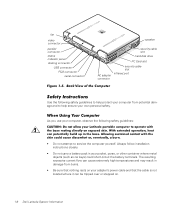
...: \\Pd-xuzhan\d\FrameMaker\Dell\sndmm003\en\999CCA00en.fm fan video connector parallel connector status indicator panel docking connector USB connector PS/2 connector serial connector speaker security cable slot hard-disk drive PC Card slot AC ...adapter connector security cable slot infrared port Use the following safety guidelines: • Do not attempt to help ensure your pocket, purse, or other container where metal objects (such as car keys) could short-circuit the battery terminals. Preliminary 1/25/00 1-6 Dell Latitude System Information DELL...
...: \\Pd-xuzhan\d\FrameMaker\Dell\sndmm003\en\999CCA00en.fm fan video connector parallel connector status indicator panel docking connector USB connector PS/2 connector serial connector speaker security cable slot hard-disk drive PC Card slot AC ...adapter connector security cable slot infrared port Use the following safety guidelines: • Do not attempt to help ensure your pocket, purse, or other container where metal objects (such as car keys) could short-circuit the battery terminals. Preliminary 1/25/00 1-6 Dell Latitude System Information DELL...
System Information Guide (multilanguage: English, Japanese, Chinese-Traditional, Chinese-Simplified, Korean, Thai)
Page 12
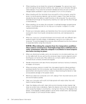
... your computer, battery, and hard-disk drive from the computer, wait 5 seconds after turning off the computer before removing the memory module or disconnecting the device to help avoid possible damage to avoid bending any connector pins. Preliminary 1/25/00 1-8 Dell Latitude System Information You can put...: \\Pd-xuzhan\d\FrameMaker\Dell\sndmm003\en\999CCA00en.fm • When traveling, do not place the computer in overhead storage compartments where it could slide around. You can put the hard-disk drive through an X-ray security machine, but never put the drive through an X-ray security...
... your computer, battery, and hard-disk drive from the computer, wait 5 seconds after turning off the computer before removing the memory module or disconnecting the device to help avoid possible damage to avoid bending any connector pins. Preliminary 1/25/00 1-8 Dell Latitude System Information You can put...: \\Pd-xuzhan\d\FrameMaker\Dell\sndmm003\en\999CCA00en.fm • When traveling, do not place the computer in overhead storage compartments where it could slide around. You can put the hard-disk drive through an X-ray security machine, but never put the drive through an X-ray security...


