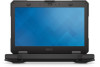
Latitude 5404 Battery - Dell
Latitude 5404 Battery
View Results Below
Free Dell Latitude 5404 manuals!
Problems with Dell Latitude 5404?
Ask a Question
Free Dell Latitude 5404 manuals!
Problems with Dell Latitude 5404?
Ask a Question
Related Manual Pages


Similar Questions


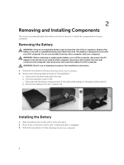
Battery
does my laptop need to be turned on in order to charge the battery
does my laptop need to be turned on in order to charge the battery
(Posted by Anonymous-45466 12 years ago)
Battery Charging
My battery charging is disabled. How do I enable it?
My battery charging is disabled. How do I enable it?
(Posted by delliott361 12 years ago)