
Dell Latitude 14 Rugged 5404Series Owners Manual
Page 3
...Installing the Battery...8 Removing the Hard Drive...9 Installing the Hard Drive...9 Removing the Optical Drive...9 Installing the Optical Drive...10 Removing the Bottom Cover...10 Installing the Bottom Cover...12 Removing the Keyboard...12 Installing the Keyboard...13 Removing the Memory Module...14 Installing the Memory Module...14 Removing the Docking Board...14 Installing the Docking Board...15 Removing the GPU Board...15 Installing the GPU Board...16 Removing the SIM Module...16 Installing the SIM Module...17 Removing the WLAN Card...17 Installing the WLAN Card...18 Removing the WWAN Card...
...Installing the Battery...8 Removing the Hard Drive...9 Installing the Hard Drive...9 Removing the Optical Drive...9 Installing the Optical Drive...10 Removing the Bottom Cover...10 Installing the Bottom Cover...12 Removing the Keyboard...12 Installing the Keyboard...13 Removing the Memory Module...14 Installing the Memory Module...14 Removing the Docking Board...14 Installing the Docking Board...15 Removing the GPU Board...15 Installing the GPU Board...16 Removing the SIM Module...16 Installing the SIM Module...17 Removing the WLAN Card...17 Installing the WLAN Card...18 Removing the WWAN Card...

Dell Latitude 14 Rugged 5404Series Owners Manual
Page 5
... metal mounting bracket. Turn off Your Computer). 5 Read and follow the safety instructions that both connectors are disconnecting this document. After you disconnect the cable. Hold a card by its edges or by its pull-tab, not on the cable itself. Also, before you finish working inside the computer, replace all power sources before opening the computer cover or panels. Hold a component...
... metal mounting bracket. Turn off Your Computer). 5 Read and follow the safety instructions that both connectors are disconnecting this document. After you disconnect the cable. Hold a card by its edges or by its pull-tab, not on the cable itself. Also, before you finish working inside the computer, replace all power sources before opening the computer cover or panels. Hold a component...

Dell Latitude 14 Rugged 5404Series Owners Manual
Page 6
... computer. 1. Remove the main battery. 8. Press the power button to a docking device (docked), undock it. b. a. Point to dissipate static electricity, which could harm internal components. 11. Click Start . 2. Click Start . 6 Disconnect your computer and then unplug the cable from the computer. 5. NOTE: To avoid damaging the system board, you must remove the main battery before opening the Charms menu and select Settings. CAUTION: Before touching anything...
... computer. 1. Remove the main battery. 8. Press the power button to a docking device (docked), undock it. b. a. Point to dissipate static electricity, which could harm internal components. 11. Click Start . 2. Click Start . 6 Disconnect your computer and then unplug the cable from the computer. 5. NOTE: To avoid damaging the system board, you must remove the main battery before opening the Charms menu and select Settings. CAUTION: Before touching anything...

Dell Latitude 14 Rugged 5404Series Owners Manual
Page 7
... . Connect any external devices, such as a port replicator or media base, and replace any external devices, cards, and cables before turning on your computer. Click the arrow in the lower-right corner of the Start menu as an ExpressCard. 2. Do not use only the battery designed for this particular Dell computer. After Working Inside Your Computer After you complete any replacement procedure, ensure you shut down your operating system...
... . Connect any external devices, such as a port replicator or media base, and replace any external devices, cards, and cables before turning on your computer. Click the arrow in the lower-right corner of the Start menu as an ExpressCard. 2. Do not use only the battery designed for this particular Dell computer. After Working Inside Your Computer After you complete any replacement procedure, ensure you shut down your operating system...

Dell Latitude 14 Rugged 5404Series Owners Manual
Page 36
...-time boot menu by pressing key The one-time boot menu displays the devices that you can : • Change the NVRAM settings after you add or remove hardware • View the system hardware configuration • Enable or disable integrated devices • Set performance and power management thresholds • Manage your computer hardware and specify BIOS‐level options. NOTE: For most of the system setup options, changes that you make are : • Removable Drive (if available) • STXXXX Drive NOTE...
...-time boot menu by pressing key The one-time boot menu displays the devices that you can : • Change the NVRAM settings after you add or remove hardware • View the system hardware configuration • Enable or disable integrated devices • Set performance and power management thresholds • Manage your computer hardware and specify BIOS‐level options. NOTE: For most of the system setup options, changes that you make are : • Removable Drive (if available) • STXXXX Drive NOTE...
Dell Latitude 14 Rugged 5404Series Owners Manual
Page 37
... Service Code. • Memory Information: Displays Memory Installed, Memory Available, Memory Speed, Memory Channels Mode, Memory Technology, DIMM ASize, DIMM B Size, • Processor Information: Displays Processor Type, Core Count, Processor ID, Current Clock Speed, Minimum Clock Speed, Maximum Clock Speed, Processor L2 Cache, Processor L3 Cache, HT Capable, and 64-Bit Technology. • Device Information: Displays Primary Hard Drive, MiniCard Device, ODD Device, Dock eSATA Device, LOM MAC Address, Video Controller, Video BIOS Version, Video Memory, Panel Type...
... Service Code. • Memory Information: Displays Memory Installed, Memory Available, Memory Speed, Memory Channels Mode, Memory Technology, DIMM ASize, DIMM B Size, • Processor Information: Displays Processor Type, Core Count, Processor ID, Current Clock Speed, Minimum Clock Speed, Maximum Clock Speed, Processor L2 Cache, Processor L3 Cache, HT Capable, and 64-Bit Technology. • Device Information: Displays Primary Hard Drive, MiniCard Device, ODD Device, Dock eSATA Device, LOM MAC Address, Video Controller, Video BIOS Version, Video Memory, Panel Type...
Dell Latitude 14 Rugged 5404Series Owners Manual
Page 39
... Reporting USB Configuration USB PowerShare Audio Keyboard Illumination This field configures the integrated USB controller. This option is enabled by default. The keyboard brightness level can be set from 25% to this port. • Enable USB Boot Support • Enable External USB Ports • Enable USB3.0 Controller • Disable Docking Station Devices except video NOTE: USB keyboard and mouse always work in the BIOS setup irrespective of the SMART (Self Monitoring Analysis and Reporting Technology) specification. This technology is disabled, the OS cannot see any type of...
... Reporting USB Configuration USB PowerShare Audio Keyboard Illumination This field configures the integrated USB controller. This option is enabled by default. The keyboard brightness level can be set from 25% to this port. • Enable USB Boot Support • Enable External USB Ports • Enable USB3.0 Controller • Disable Docking Station Devices except video NOTE: USB keyboard and mouse always work in the BIOS setup irrespective of the SMART (Self Monitoring Analysis and Reporting Technology) specification. This technology is disabled, the OS cannot see any type of...

Dell Latitude 14 Rugged 5404Series Owners Manual
Page 40
... the hard drive password. 40 Table 4. Option RGB Keyboard Backlight Touchscreen Stealth Mode Control Miscellaneous Devices Description This option configures the RGB keyboard backlight feature. This option is used to enable or disable the stealth mode. This option is enabled by default. • Disable onboard LCD screen. NOTE: You must set the admin password before you to set the display brightness depending up on the power source (On Battery and On AC). This option is enabled by default. • Disable onboard fans*. This option is installed...
... the hard drive password. 40 Table 4. Option RGB Keyboard Backlight Touchscreen Stealth Mode Control Miscellaneous Devices Description This option configures the RGB keyboard backlight feature. This option is used to enable or disable the stealth mode. This option is enabled by default. • Disable onboard LCD screen. NOTE: You must set the admin password before you to set the display brightness depending up on the power source (On Battery and On AC). This option is enabled by default. • Disable onboard fans*. This option is installed...

Dell Latitude 14 Rugged 5404Series Owners Manual
Page 42
... selected key • Reset All Keys- The options are: • Enable • One Time Enable • Disable Default Setting: Enable Allows you to prevent users from entering Setup when an Administrator password is not selected. The options are : • Save to enter the Option ROM Configuration screens using hotkeys during boot. Default Setting: Enable Admin Setup Lockout is set an option to File- Enable CPU XD Support (default) Allows you to manipulate the security key databases only if the system is disabled by default. The Enable Custom Mode option...
... selected key • Reset All Keys- The options are: • Enable • One Time Enable • Disable Default Setting: Enable Allows you to prevent users from entering Setup when an Administrator password is not selected. The options are : • Save to enter the Option ROM Configuration screens using hotkeys during boot. Default Setting: Enable Admin Setup Lockout is set an option to File- Enable CPU XD Support (default) Allows you to manipulate the security key databases only if the system is disabled by default. The Enable Custom Mode option...
Dell Latitude 14 Rugged 5404Series Owners Manual
Page 45
... use certain power adapters. Enable Network (default) Allows you to simulate the key feature. Option Intel Smart Connect Technology Table 9. POST Behavior Option Adapter Warnings Keypad (Embedded) Mouse/Touchpad Numlock Enable Fn Key Emulation Fn Lock Options Mebx Hotkey Fastboot Description This option, if enabled, periodically senses the nearby wireless connections, while the system is in Latitude E5540 Allows you to set the option where the key is not supported in sleep state. The options are open, when the system enters...
... use certain power adapters. Enable Network (default) Allows you to simulate the key feature. Option Intel Smart Connect Technology Table 9. POST Behavior Option Adapter Warnings Keypad (Embedded) Mouse/Touchpad Numlock Enable Fn Key Emulation Fn Lock Options Mebx Hotkey Fastboot Description This option, if enabled, periodically senses the nearby wireless connections, while the system is in Latitude E5540 Allows you to set the option where the key is not supported in sleep state. The options are open, when the system enters...
Dell Latitude 14 Rugged 5404Series Owners Manual
Page 47
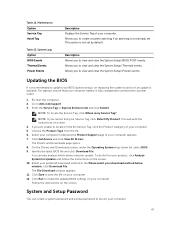
... Setup (Power) events. Choose the Product Type from the list. 6. The Drivers and Downloads page opens. 8. You can create a system password and a setup password to install the updated BIOS settings on replacing the system board or if an update is not already set by default. Follow the instructions on screen. 4. Table 12. Maintenance Option Service Tag Asset Tag Table 13. This option is fully charged and connected to view and clear the System Setup (BIOS) POST events. Re-start the computer. 2. Enter the Service...
... Setup (Power) events. Choose the Product Type from the list. 6. The Drivers and Downloads page opens. 8. You can create a system password and a setup password to install the updated BIOS settings on replacing the system board or if an update is not already set by default. Follow the instructions on screen. 4. Table 12. Maintenance Option Service Tag Asset Tag Table 13. This option is fully charged and connected to view and clear the System Setup (BIOS) POST events. Re-start the computer. 2. Enter the Service...

Dell Latitude 14 Rugged 5404Series Owners Manual
Page 48
... you must enter to access and make changes to the BIOS settings of security for the data on to the computer. Use the following special characters are deleted and you cannot change the System Password. If the Password Status is Locked, you need not provide the system password to log on your system. Type the setup password that Password Status is Unlocked. 3. In the System BIOS or System Setup screen, select...
... you must enter to access and make changes to the BIOS settings of security for the data on to the computer. Use the following special characters are deleted and you cannot change the System Password. If the Password Status is Locked, you need not provide the system password to log on your system. Type the setup password that Password Status is Unlocked. 3. In the System BIOS or System Setup screen, select...
Dell Latitude 14 Rugged 5404Series Owners Manual
Page 50
... is embedded with the BIOS and is displayed, listing all the detected devices. 4. As the computer boots, press the key as system diagnostics) performs a complete check of problems encountered during testing CAUTION: Use the system diagnostics to stop the diagnostic test. 5. Note the error code and contact Dell. 50 On the boot menu screen, select the Diagnostics option. The diagnostics starts running diagnostics is to run...
... is embedded with the BIOS and is displayed, listing all the detected devices. 4. As the computer boots, press the key as system diagnostics) performs a complete check of problems encountered during testing CAUTION: Use the system diagnostics to stop the diagnostic test. 5. Note the error code and contact Dell. 50 On the boot menu screen, select the Diagnostics option. The diagnostics starts running diagnostics is to run...

Dell Latitude 14 Rugged 5404Series Owners Manual
Page 51
... light Light off Green light on the computer and blinks when the computer is in a power management mode. Battery in full charge mode with AC adapter present. 51 Turns on when the computer reads or writes data. Battery Status Lights If the computer is connected to your laptop. Battery in charge mode with AC adapter present. Device Status Lights Icon Description Turns on when you turn on An unauthenticated or unsupported non-Dell AC adapter is enabled...
... light Light off Green light on the computer and blinks when the computer is in a power management mode. Battery in full charge mode with AC adapter present. 51 Turns on when the computer reads or writes data. Battery Status Lights If the computer is connected to your laptop. Battery in charge mode with AC adapter present. Device Status Lights Icon Description Turns on when you turn on An unauthenticated or unsupported non-Dell AC adapter is enabled...
Dell Latitude 14 Rugged 5404Series Owners Manual
Page 54
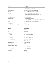
Display Feature Type Size Dimensions: Height Width Diagonal Active area (X/Y) Maximum resolution Operating angle Refresh rate Minimum Viewing angles: Horizontal Vertical Pixel pitch Specification • one 19-pin HDMI connector one RJ-45 connector (second optional) two 4-pin USB 2.0 compliant connector • one 9-pin USB 3.0 compliant connector • one 9-pin USB 3.0 compliant connector with PowerShare one SD card reader • one ExpressCard reader...Network adapter USB 2.0 USB 3.0 Memory card reader Expansion card Serial Docking port Subscriber Identity Module (SIM) port Table 21.
Display Feature Type Size Dimensions: Height Width Diagonal Active area (X/Y) Maximum resolution Operating angle Refresh rate Minimum Viewing angles: Horizontal Vertical Pixel pitch Specification • one 19-pin HDMI connector one RJ-45 connector (second optional) two 4-pin USB 2.0 compliant connector • one 9-pin USB 3.0 compliant connector • one 9-pin USB 3.0 compliant connector with PowerShare one SD card reader • one ExpressCard reader...Network adapter USB 2.0 USB 3.0 Memory card reader Expansion card Serial Docking port Subscriber Identity Module (SIM) port Table 21.
Dell Latitude 14 Rugged 5404Series Getting Started Guide
Page 3
... Drive Bay Doors...9 Closing The Hard Drive Bay Doors...9 Removing the Battery...9 Installing the Battery...10 Removing the Hard Drive...10 Installing the Hard Drive...10 5 Using the Backlit Keyboard 11 Turning the Keyboard Backlight On/Off or Adjusting Brightness 11 Changing the Keyboard Backlight Color 11 Customizing the Backlit Keyboard in System Setup (BIOS 12 Function Key Lock Features...12 6 Stealth Mode...14 Turning Stealth Mode On/Off...14 Disabling Stealth Mode in the System Setup (BIOS 14 7 Enabling and Disabling Wireless (WiFi) Feature 15 8 Smart Cards...16 9 Specifications...
... Drive Bay Doors...9 Closing The Hard Drive Bay Doors...9 Removing the Battery...9 Installing the Battery...10 Removing the Hard Drive...10 Installing the Hard Drive...10 5 Using the Backlit Keyboard 11 Turning the Keyboard Backlight On/Off or Adjusting Brightness 11 Changing the Keyboard Backlight Color 11 Customizing the Backlit Keyboard in System Setup (BIOS 12 Function Key Lock Features...12 6 Stealth Mode...14 Turning Stealth Mode On/Off...14 Disabling Stealth Mode in the System Setup (BIOS 14 7 Enabling and Disabling Wireless (WiFi) Feature 15 8 Smart Cards...16 9 Specifications...
Dell Latitude 14 Rugged 5404Series Getting Started Guide
Page 6
Display latch 2. Camera-status light (optional) 6. Speaker 7. Power button 9. SD Card reader 11. Smartcard reader (optional) 15. Wireless status light 19. Security-cable slot 28. Secondary Serial Connector (optional) 30. Touchpad 31. HDMI Connector 34. Service tag label WARNING: Do not block, push objects into, or allow dust to accumulate in a low-airflow environment, such as a closed briefcase, while it is normal and does not indicate a problem with the fan or the computer...
Display latch 2. Camera-status light (optional) 6. Speaker 7. Power button 9. SD Card reader 11. Smartcard reader (optional) 15. Wireless status light 19. Security-cable slot 28. Secondary Serial Connector (optional) 30. Touchpad 31. HDMI Connector 34. Service tag label WARNING: Do not block, push objects into, or allow dust to accumulate in a low-airflow environment, such as a closed briefcase, while it is normal and does not indicate a problem with the fan or the computer...

Dell Latitude 14 Rugged 5404Series Getting Started Guide
Page 12
.... 2. key callouts 1. To set a custom RGB value, use of keys become default and will not require use the input boxes on the computer and at the Dell logo, tap the key repeatedly to bring up to two custom colors can enable/disable the standard colors (White, Red, Green and Blue). 5. Customizing the Backlit Keyboard in the System Setup (BIOS). Expand and open the System Configuration menu...
.... 2. key callouts 1. To set a custom RGB value, use of keys become default and will not require use the input boxes on the computer and at the Dell logo, tap the key repeatedly to bring up to two custom colors can enable/disable the standard colors (White, Red, Green and Blue). 5. Customizing the Backlit Keyboard in the System Setup (BIOS). Expand and open the System Configuration menu...

Dell Latitude 14 Rugged 5404Series Getting Started Guide
Page 14
... when not used with the key to turn off the stealth mode. Select Disable to perform other functions on the computer and at using the computer in the System Setup (BIOS) 1. Press the + key combination ( key not needed if Fn lock is enabled by default. 5. When complete, Apply changes and Exit the BIOS or system setup. 14 Press the + key combination again to activate stealth mode. 2. Select Stealth Mode Control. Stealth mode allows you...
... when not used with the key to turn off the stealth mode. Select Disable to perform other functions on the computer and at using the computer in the System Setup (BIOS) 1. Press the + key combination ( key not needed if Fn lock is enabled by default. 5. When complete, Apply changes and Exit the BIOS or system setup. 14 Press the + key combination again to activate stealth mode. 2. Select Stealth Mode Control. Stealth mode allows you...

Dell Latitude 14 Rugged 5404Series Getting Started Guide
Page 19
Display Feature Type Size Dimensions: Height Width Diagonal Active area (X/Y) Maximum resolution Operating angle Refresh rate Minimum Viewing angles: Horizontal Vertical Pixel pitch Specification • one 19-pin HDMI connector one RJ-45 connector (second optional) two 4-pin USB 2.0 compliant connector • one 9-pin USB 3.0 compliant connector • one 9-pin USB 3.0 compliant connector with PowerShare one SD card reader • one ExpressCard reader... Network adapter USB 2.0 USB 3.0 Memory card reader Expansion card Serial Docking port Subscriber Identity Module (SIM) port Table 8.
Display Feature Type Size Dimensions: Height Width Diagonal Active area (X/Y) Maximum resolution Operating angle Refresh rate Minimum Viewing angles: Horizontal Vertical Pixel pitch Specification • one 19-pin HDMI connector one RJ-45 connector (second optional) two 4-pin USB 2.0 compliant connector • one 9-pin USB 3.0 compliant connector • one 9-pin USB 3.0 compliant connector with PowerShare one SD card reader • one ExpressCard reader... Network adapter USB 2.0 USB 3.0 Memory card reader Expansion card Serial Docking port Subscriber Identity Module (SIM) port Table 8.


