
Setup and specifications guide
Page 3
......12 Storage...13 System board connectors...13 Media card-reader...13 Audio...14 Video card...14 Camera...14 Mobile Broadband...15 Wireless...15 Ports and connectors...15 Display...16 Dell Active Pen specifications...16 Keyboard...17 Keyboard shortcuts...17 Touchpad...18 Fingerprint reader-optional...18 Operating system...19 Battery...19 Power adapter...
......12 Storage...13 System board connectors...13 Media card-reader...13 Audio...14 Video card...14 Camera...14 Mobile Broadband...15 Wireless...15 Ports and connectors...15 Display...16 Dell Active Pen specifications...16 Keyboard...17 Keyboard shortcuts...17 Touchpad...18 Fingerprint reader-optional...18 Operating system...19 Battery...19 Power adapter...

Setup and specifications guide
Page 9
Smart card reader (optional) Right view 1. Left view 1. USB 3.1 Gen 1 port 5. microSD card reader 3. Wedge-shaped lock slot Chassis overview 9 HDMI port 4. USB 3.1 Gen 1 port with DisplayPort/ Power Delivery/ Thunderbolt (optional) 3. micro-SIM card slot 4. Power connector port 2. USB 3.1 Gen 2(USB Type-C) port with PowerShare 5. Headset/ Microphone port 2.
Smart card reader (optional) Right view 1. Left view 1. USB 3.1 Gen 1 port 5. microSD card reader 3. Wedge-shaped lock slot Chassis overview 9 HDMI port 4. USB 3.1 Gen 1 port with DisplayPort/ Power Delivery/ Thunderbolt (optional) 3. micro-SIM card slot 4. Power connector port 2. USB 3.1 Gen 2(USB Type-C) port with PowerShare 5. Headset/ Microphone port 2.

Setup and specifications guide
Page 14
...-8665U CPU (vPro) • Intel Core i5-8265U CPU • Intel Core i5-8365U CPU (vPro) • Intel Core i3-8145U CPU Shared system HDMI 1.4 port memory Maximum resolution 1920x1200@60Hz Camera Table 10. Camera specifications Feature Camera Type Specifications RGB, HD fixed focus 14 Technical specifications Audio Table 8. Audio specifications...
...-8665U CPU (vPro) • Intel Core i5-8265U CPU • Intel Core i5-8365U CPU (vPro) • Intel Core i3-8145U CPU Shared system HDMI 1.4 port memory Maximum resolution 1920x1200@60Hz Camera Table 10. Camera specifications Feature Camera Type Specifications RGB, HD fixed focus 14 Technical specifications Audio Table 8. Audio specifications...

Setup and specifications guide
Page 15
...micro SIM • One USB 3.1 Gen 1 • One USB 3.1 Gen 1 with PowerShare • One USB 3.1 Gen 2(USB Type-C) port with DisplayPort/ Thunderbolt/ Power Delivery(optional) Wedge-shaped lock slot Universal Jack (Global Headset Jack + mic phone in + line in support) One HDMI ....11ac Dual Band (2x2) Wireless Adapter + Bluetooth 4.2 Intel Wi-Fi 6 AX200 2x2 .11ax 160MHz + Bluetooth 5.0 Intel XMM 7360 Global LTE-Advanced Ports and connectors Table 13. Feature IR Camera Specifications 6 mm IR camera (optional) Resolution Still image: HD resolution (1280x720) Video: HD resolution (1280x720)...
...micro SIM • One USB 3.1 Gen 1 • One USB 3.1 Gen 1 with PowerShare • One USB 3.1 Gen 2(USB Type-C) port with DisplayPort/ Thunderbolt/ Power Delivery(optional) Wedge-shaped lock slot Universal Jack (Global Headset Jack + mic phone in + line in support) One HDMI ....11ac Dual Band (2x2) Wireless Adapter + Bluetooth 4.2 Intel Wi-Fi 6 AX200 2x2 .11ax 160MHz + Bluetooth 5.0 Intel XMM 7360 Global LTE-Advanced Ports and connectors Table 13. Feature IR Camera Specifications 6 mm IR camera (optional) Resolution Still image: HD resolution (1280x720) Video: HD resolution (1280x720)...
Setup and specifications guide
Page 28
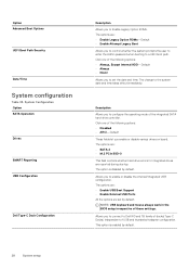
.... Click one of the integrated SATA hard-drive controller. The options are: • Enable USB Boot Support • Enable External USB Ports All the options are reported during startup. The option is enabled by default. System Configuration Option SATA Operation Drives SMART Reporting USB Configuration...you to Enable Legacy Option ROMs. The options are: • Enable Legacy Option ROMs-Default • Enable Attempt Legacy Boot Allows you to Dell WD and TB family of docks(Type-C Docks) independent of these settings. Allows you to control whether the system prompts the user to enter...
.... Click one of the integrated SATA hard-drive controller. The options are: • Enable USB Boot Support • Enable External USB Ports All the options are reported during startup. The option is enabled by default. System Configuration Option SATA Operation Drives SMART Reporting USB Configuration...you to Enable Legacy Option ROMs. The options are: • Enable Legacy Option ROMs-Default • Enable Attempt Legacy Boot Allows you to Dell WD and TB family of docks(Type-C Docks) independent of these settings. Allows you to control whether the system prompts the user to enter...

Setup and specifications guide
Page 29
... Thunderbolt (and PCIe behind TBT) Pre-boot With following security levels : • No Security • User Authentication (Enabled by Defualt) • Secure Connect • Display Port and USB Only This option configures the method used by the Thunderbolt controller to perform PCIe device enumeration. • Auto Switch : The BIOS will automatically...
... Thunderbolt (and PCIe behind TBT) Pre-boot With following security levels : • No Security • User Authentication (Enabled by Defualt) • Secure Connect • Display Port and USB Only This option configures the method used by the Thunderbolt controller to perform PCIe device enumeration. • Auto Switch : The BIOS will automatically...

Service Manual
Page 4
... Removing the system fan...44 Installing the system fan...46 Heat sink...48 Removing the heatsink - UMA...49 DC-in port...49 Removing the DC-in port...49 Installing the DC-in port...51 LED board...53 Removing the LED board...53 Installing the LED board...56 Touchpad button board...59 Removing the... Enhanced Pre-Boot System Assessment (ePSA) diagnostics 94 Running the ePSA diagnostics...94 System diagnostic lights...94 WiFi power cycle...95 6 Getting help...96 Contacting Dell...96 4 Contents
... Removing the system fan...44 Installing the system fan...46 Heat sink...48 Removing the heatsink - UMA...49 DC-in port...49 Removing the DC-in port...49 Installing the DC-in port...51 LED board...53 Removing the LED board...53 Installing the LED board...56 Touchpad button board...59 Removing the... Enhanced Pre-Boot System Assessment (ePSA) diagnostics 94 Running the ePSA diagnostics...94 System diagnostic lights...94 WiFi power cycle...95 6 Getting help...96 Contacting Dell...96 4 Contents

Service Manual
Page 11
...This is just a connector shape, and the underlying technology could charge your laptop from one little USB Type-C connection. USB Type-C ports can be transferred at speeds up to charge. Currently, smartphones, tablets, and other types of different protocols using "alternate modes," which... a single connector standard that every device should be USB 2 or USB 3.0. Thunderbolt 1 and Thunderbolt 3 1. Thunderbolt 3 uses a USB Type-C connector/port to connect to any dock, display or data device like an external hard drive. USB 3's theoretical bandwidth is 5 Gbps, while USB 3.1's is a ...
...This is just a connector shape, and the underlying technology could charge your laptop from one little USB Type-C connection. USB Type-C ports can be transferred at speeds up to charge. Currently, smartphones, tablets, and other types of different protocols using "alternate modes," which... a single connector standard that every device should be USB 2 or USB 3.0. Thunderbolt 1 and Thunderbolt 3 1. Thunderbolt 3 uses a USB Type-C connector/port to connect to any dock, display or data device like an external hard drive. USB 3's theoretical bandwidth is 5 Gbps, while USB 3.1's is a ...

Service Manual
Page 14
... charge is complete the LED turns off ). 2. Solid white -the battery is turned off . • If the computer is running on either side of RJ45 port Link speed indicator (LHS) Activity indicator (RHS) Green Amber 14 Technology and components A low battery state is approximately 30 minutes or less of the system...
... charge is complete the LED turns off ). 2. Solid white -the battery is turned off . • If the computer is running on either side of RJ45 port Link speed indicator (LHS) Activity indicator (RHS) Green Amber 14 Technology and components A low battery state is approximately 30 minutes or less of the system...

Service Manual
Page 15
DC-in port Major components of your system 15 Base cover 2. 3 Major components of your system 1.
DC-in port Major components of your system 15 Base cover 2. 3 Major components of your system 1.

Service Manual
Page 49
...in after working inside your computer. 2. Remove the base cover. 4. Installing the heatsink - In sequential order (as indicated on the system board [1]. 2. DC-in port Removing the DC-in before working inside your computer. Disassembly and reassembly 49 UMA Steps 1. Follow the procedure in... port Prerequisites 1. Replace the battery. 2. Replace the base cover. 3. Place the heatsink on the system board and align the screw holes on the heatsink ...
...in after working inside your computer. 2. Remove the base cover. 4. Installing the heatsink - In sequential order (as indicated on the system board [1]. 2. DC-in port Removing the DC-in before working inside your computer. Disassembly and reassembly 49 UMA Steps 1. Follow the procedure in... port Prerequisites 1. Replace the battery. 2. Replace the base cover. 3. Place the heatsink on the system board and align the screw holes on the heatsink ...

Service Manual
Page 50
Remove the two (M2x4) screws that secure the Type-C bracket to the system board [1]. 2. Lift the Type-C bracket away from the computer [1, 2]. 50 Disassembly and reassembly Disconnect the DC-in port cable from the connector on the system board and remove the DC-in port from the computer [2]. 3. Steps 1.
Remove the two (M2x4) screws that secure the Type-C bracket to the system board [1]. 2. Lift the Type-C bracket away from the computer [1, 2]. 50 Disassembly and reassembly Disconnect the DC-in port cable from the connector on the system board and remove the DC-in port from the computer [2]. 3. Steps 1.

Service Manual
Page 51
Connect the DC-in port Steps 1. Installing the DC-in port cable to its slot on the system board [2]. Place the DC-in port to the connector on the computer [1]. 2. Disassembly and reassembly 51
Connect the DC-in port Steps 1. Installing the DC-in port cable to its slot on the system board [2]. Place the DC-in port to the connector on the computer [1]. 2. Disassembly and reassembly 51

Service Manual
Page 64
Lift the fingerprint support bracket away from the computer [2]. 6. Disconnect the fingerprint port [3]. 64 Disassembly and reassembly 4. Remove the single (M2.5x4) screw that secures the fingerprint support bracket to the system board [1]. 5.
Lift the fingerprint support bracket away from the computer [2]. 6. Disconnect the fingerprint port [3]. 64 Disassembly and reassembly 4. Remove the single (M2.5x4) screw that secures the fingerprint support bracket to the system board [1]. 5.


