
Dell Latitude 10 - ST2e Owner's Manual
Page 3
...Inside Your Computer...6 2 Removing and Installing Components 9 Recommended Tools...9 Internal View...9 Removing the Base Cover...10 Installing the Base Cover...10 Removing the Battery...10 Installing the Battery...11 Removing the Front Camera...11 Installing the Front Camera...12 Removing the Speakers...12 Installing the Speakers...the System Board...16 Removing the Rear Camera...17 Installing the Rear Camera...17 Removing the Coin-Cell Battery...18 Installing the Coin-Cell Battery...18 Removing the Volume-Button Board...18 Installing the Volume-Button Board...19 3 System Setup...21 Entering ...
...Inside Your Computer...6 2 Removing and Installing Components 9 Recommended Tools...9 Internal View...9 Removing the Base Cover...10 Installing the Base Cover...10 Removing the Battery...10 Installing the Battery...11 Removing the Front Camera...11 Installing the Front Camera...12 Removing the Speakers...12 Installing the Speakers...the System Board...16 Removing the Rear Camera...17 Installing the Rear Camera...17 Removing the Coin-Cell Battery...18 Installing the Coin-Cell Battery...18 Removing the Volume-Button Board...18 Installing the Volume-Button Board...19 3 System Setup...21 Entering ...

Dell Latitude 10 - ST2e Owner's Manual
Page 6
...electrical shock, always unplug your operating system, press and hold the power button for about 4 seconds to the computer, use batteries designed for this particular Dell computer. Remove any external devices, cards, and cables before you service the computer. 7. Select the and then select Shut ... metal surface to dissipate static electricity, which could harm internal components. 10. NOTE: To avoid damaging the system board, you must remove the main battery before turning on the down. Remove the main battery. 8. While you shut down the operating system: - Click on ...
...electrical shock, always unplug your operating system, press and hold the power button for about 4 seconds to the computer, use batteries designed for this particular Dell computer. Remove any external devices, cards, and cables before you service the computer. 7. Select the and then select Shut ... metal surface to dissipate static electricity, which could harm internal components. 10. NOTE: To avoid damaging the system board, you must remove the main battery before turning on the down. Remove the main battery. 8. While you shut down the operating system: - Click on ...

Dell Latitude 10 - ST2e Owner's Manual
Page 9
2 Removing and Installing Components This section provides detailed information on how to remove or install the components from your computer. Recommended Tools The procedures in this document may require the following tools: • Small flat-blade screwdriver • #0 Phillips screwdriver • #1 Phillips screwdriver • Small plastic scribe Internal View Figure 1. front camera 3. battery 9 Internal View 1. rear camera 4. system board 2.
2 Removing and Installing Components This section provides detailed information on how to remove or install the components from your computer. Recommended Tools The procedures in this document may require the following tools: • Small flat-blade screwdriver • #0 Phillips screwdriver • #1 Phillips screwdriver • Small plastic scribe Internal View Figure 1. front camera 3. battery 9 Internal View 1. rear camera 4. system board 2.
Dell Latitude 10 - ST2e Owner's Manual
Page 10
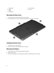
... Base Cover 1. Follow the procedures in After Working Inside Your Computer. volume button 6. Remove the base cover. 3. coin-cell battery 10. 5. speaker 7. battery 8. Attach the base cover to the computer and lift the battery from the computer by following the arrow sequence in Before Working Inside Your Computer. 2. Follow the procedures in the diagram...
... Base Cover 1. Follow the procedures in After Working Inside Your Computer. volume button 6. Remove the base cover. 3. coin-cell battery 10. 5. speaker 7. battery 8. Attach the base cover to the computer and lift the battery from the computer by following the arrow sequence in Before Working Inside Your Computer. 2. Follow the procedures in the diagram...

Dell Latitude 10 - ST2e Owner's Manual
Page 11
Install the base cover. 3. Follow the procedures in Before Working Inside Your Computer. 2. Remove the: a) base cover b) battery 3. Remove the screw that secures the camera module to the computer. 2. Installing the Battery 1. Follow the procedures in After Working Inside Your Computer. Tighten the screws to secure the battery to the computer. Removing the Front Camera 1. Remove the camera module from the computer. 11 Lift up the connector latch and disconnect the camera cable.
Install the base cover. 3. Follow the procedures in Before Working Inside Your Computer. 2. Remove the: a) base cover b) battery 3. Remove the screw that secures the camera module to the computer. 2. Installing the Battery 1. Follow the procedures in After Working Inside Your Computer. Tighten the screws to secure the battery to the computer. Removing the Front Camera 1. Remove the camera module from the computer. 11 Lift up the connector latch and disconnect the camera cable.

Dell Latitude 10 - ST2e Owner's Manual
Page 12
Tighten the screw to secure the camera module to the computer. 12 Lift up the coin-cell battery from its slot on the computer. 2. Install the: a) battery b) base cover 5. Remove the : a) base cover b) battery 3. Disconnect the speaker connector from below the speaker. Remove the screws that secure the speakers to the computer. 3. Follow the...
Tighten the screw to secure the camera module to the computer. 12 Lift up the coin-cell battery from its slot on the computer. 2. Install the: a) battery b) base cover 5. Remove the : a) base cover b) battery 3. Disconnect the speaker connector from below the speaker. Remove the screws that secure the speakers to the computer. 3. Follow the...

Dell Latitude 10 - ST2e Owner's Manual
Page 14
...front camera 3. Installing the Speakers 1. Route the speaker cables on the system board. 6. Removing the Docking Board 1. Place the coin-cell battery in After Working Inside Your Computer. Follow the procedures in its port on the chassis. 3. Follow the procedures in their slot. 2. Tighten... the screws to secure the speakers to its slot and route the cables. 5. Install the : a) battery b) base cover 7. Lift up the connector latch and disconnect the docking-board power cable from the connector. 14 Place the right and the left speakers...
...front camera 3. Installing the Speakers 1. Route the speaker cables on the system board. 6. Removing the Docking Board 1. Place the coin-cell battery in After Working Inside Your Computer. Follow the procedures in its port on the chassis. 3. Follow the procedures in their slot. 2. Tighten... the screws to secure the speakers to its slot and route the cables. 5. Install the : a) battery b) base cover 7. Lift up the connector latch and disconnect the docking-board power cable from the connector. 14 Place the right and the left speakers...

Dell Latitude 10 - ST2e Owner's Manual
Page 15
Remove the screws that secure the docking board to the computer. 3. Tighten the screws to secure the docking board to the computer. 5. Connect the docking-board power cable to the docking board and place the docking board in its slot in After Working Inside Your Computer. 15 Follow the procedures in the computer. 2. Install the: a) front camera b) speaker c) battery d) base cover 5. Remove the docking board from the computer and disconnect the home-button board cable. Installing the Docking Board 1. Connect the home-button board cable to the connector. 4. 4.
Remove the screws that secure the docking board to the computer. 3. Tighten the screws to secure the docking board to the computer. 5. Connect the docking-board power cable to the docking board and place the docking board in its slot in After Working Inside Your Computer. 15 Follow the procedures in the computer. 2. Install the: a) front camera b) speaker c) battery d) base cover 5. Remove the docking board from the computer and disconnect the home-button board cable. Installing the Docking Board 1. Connect the home-button board cable to the connector. 4. 4.

Dell Latitude 10 - ST2e Owner's Manual
Page 16
... the computer. 2. Installing the System Board 1. Tighten the screws to secure the system board to the computer. 5. Removing the System Board 1. Remove the: a) base cover b) battery c) speaker d) front camera e) docking board 3. Disconnect the LVDS and docking board cables. 4. Place the system board in Before Working Inside Your Computer. 2. Remove the screws...
... the computer. 2. Installing the System Board 1. Tighten the screws to secure the system board to the computer. 5. Removing the System Board 1. Remove the: a) base cover b) battery c) speaker d) front camera e) docking board 3. Disconnect the LVDS and docking board cables. 4. Place the system board in Before Working Inside Your Computer. 2. Remove the screws...

Dell Latitude 10 - ST2e Owner's Manual
Page 17
... Follow the procedures in Before Working Inside Your Computer. 2. Removing the Rear Camera 1. 4. Install the: a) docking board b) front camera c) speaker d) battery e) base cover 5. Place the camera module in After Working Inside Your Computer. Installing the Rear Camera 1. Remove the camera module from the system board. Follow... the procedures in its slot on the system board. 2. Install the: a) system board b) front camera c) speaker d) battery e) base cover 3. Remove the: a) base cover b) battery c) speaker d) front camera e) system board 3.
... Follow the procedures in Before Working Inside Your Computer. 2. Removing the Rear Camera 1. 4. Install the: a) docking board b) front camera c) speaker d) battery e) base cover 5. Place the camera module in After Working Inside Your Computer. Installing the Rear Camera 1. Remove the camera module from the system board. Follow... the procedures in its slot on the system board. 2. Install the: a) system board b) front camera c) speaker d) battery e) base cover 3. Remove the: a) base cover b) battery c) speaker d) front camera e) system board 3.

Dell Latitude 10 - ST2e Owner's Manual
Page 18
... in its slot on the computer. 4. Remove the: a) base cover b) battery c) speaker d) front camera e) system board 3. Connect the coin-cell battery cable to the system board. 2. Disconnect the coin-cell battery cable and remove it from the computer. Replace the coin-cell battery in After Working Inside Your Computer. Follow the procedures in Before...
... in its slot on the computer. 4. Remove the: a) base cover b) battery c) speaker d) front camera e) system board 3. Connect the coin-cell battery cable to the system board. 2. Disconnect the coin-cell battery cable and remove it from the computer. Replace the coin-cell battery in After Working Inside Your Computer. Follow the procedures in Before...

Dell Latitude 10 - ST2e Owner's Manual
Page 19
Remove the volume-button board from the connector. Follow the procedures in it 's slot on the computer. 2. Disconnect the volume-board cable from the computer Installing the Volume-Button Board 1. Pry the sides of the volume-button board with a flat-head screw driver to the connector. 3. Route and connect the volume-board cable to loosen it from the system board. 4. Place the volume-button board in After Working Inside Your Computer. 19 Install the: a) battery b) base cover 4. Lift up and remove the volume-board cable from it 's slot on the computer. b) battery 3.
Remove the volume-button board from the connector. Follow the procedures in it 's slot on the computer. 2. Disconnect the volume-board cable from the computer Installing the Volume-Button Board 1. Pry the sides of the volume-button board with a flat-head screw driver to the connector. 3. Route and connect the volume-board cable to loosen it from the system board. 4. Place the volume-button board in After Working Inside Your Computer. 19 Install the: a) battery b) base cover 4. Lift up and remove the volume-board cable from it 's slot on the computer. b) battery 3.

Dell Latitude 10 - ST2e Owner's Manual
Page 22
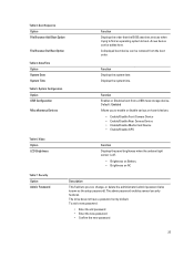
Boot Menu Press when the Dell logo appears to the boot order stored in the BIOS...navigate the System Setup by using your finger or an interactive pen. Table 2. Battery Information Option AC Adapter Battery Status Battery Charge State Battery Health Function Displays the AC Adapter information. Defaults Icon Load setup defaults. Using ... This menu is charging/discharging. System Setup (BIOS) Options Table 1. Displays the memory speed. Displays the battery health. 22 Exit Icon Exits System Setup. Displays the memory available on the computer. Keystroke Action connected to...
Boot Menu Press when the Dell logo appears to the boot order stored in the BIOS...navigate the System Setup by using your finger or an interactive pen. Table 2. Battery Information Option AC Adapter Battery Status Battery Charge State Battery Health Function Displays the AC Adapter information. Defaults Icon Load setup defaults. Using ... This menu is charging/discharging. System Setup (BIOS) Options Table 1. Displays the memory speed. Displays the battery health. 22 Exit Icon Exits System Setup. Displays the memory available on the computer. Keystroke Action connected to...
Dell Latitude 10 - ST2e Owner's Manual
Page 23
... AC Table 7. Displays the system time. Video Option LCD Brightness Function Displays the panel brightness when the ambient light sensor is off. • Brightness on Battery • Brightness on -board devices. • Enable/Disable Front Camera Device • Enable/Disable Rear Camera Device • Enable/Disable Media Card Device • Enable...
... AC Table 7. Displays the system time. Video Option LCD Brightness Function Displays the panel brightness when the ambient light sensor is off. • Brightness on Battery • Brightness on -board devices. • Enable/Disable Front Camera Device • Enable/Disable Rear Camera Device • Enable/Disable Media Card Device • Enable...
Dell Latitude 10 - ST2e Owner's Manual
Page 27
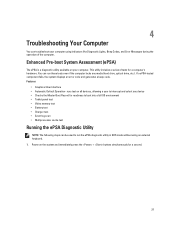
..., and Error Messages during the operation of tests for readiness to boot into a full OS environment • Tablet panel test • Video memory test • Battery test • Charger test • Event log scan • Multiprocessor cache test Running the ePSA Diagnostic Utility NOTE: The following steps can be used to...
..., and Error Messages during the operation of tests for readiness to boot into a full OS environment • Tablet panel test • Video memory test • Battery test • Charger test • Event log scan • Multiprocessor cache test Running the ePSA Diagnostic Utility NOTE: The following steps can be used to...

Dell Latitude 10 - ST2e Owner's Manual
Page 30
... /O chip failure , Keyboard controller test failure System board failure 4 RAM Read/Write failure Memory failure 5 Real-time clock power fail CMOS battery failure 30 Code 1 Cause and Troubleshooting Steps System board: BIOS ROM failure System board failure, covers BIOS corruption or ROM error 2 Memory... failure , Keyboard controller test failure System board failure RAM Read/Write failure Memory failure Real-time clock power fail CMOS battery failure Video BIOS test failure Video card failure CPU - The Power Button LED blinks the corresponding LED codes for the corresponding fault ...
... /O chip failure , Keyboard controller test failure System board failure 4 RAM Read/Write failure Memory failure 5 Real-time clock power fail CMOS battery failure 30 Code 1 Cause and Troubleshooting Steps System board: BIOS ROM failure System board failure, covers BIOS corruption or ROM error 2 Memory... failure , Keyboard controller test failure System board failure RAM Read/Write failure Memory failure Real-time clock power fail CMOS battery failure Video BIOS test failure Video card failure CPU - The Power Button LED blinks the corresponding LED codes for the corresponding fault ...
Dell Latitude 10 - ST2e Owner's Manual
Page 34
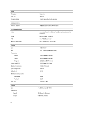
...reader Display Type Size Dimensions: Height Width Diagonal Active area (X/Y) Maximum resolution Typical brightness Refresh rate Minimum viewing angles: Horizontal Vertical Pixel pitch Battery Type Dimensions Length Height 34 integrated internal Intel Graphics Media Accelerator USB 2.0 based Gigabit LAN via dock one microphone-in and stereo headphones/...one mini HDMI connector one USB 2.0 connector one 3-in-1 memory card reader HD IPS LED 10.1 inches high definition (HD) 125.11 mm (4.93 inches) 222.52 mm (8.76 inches) 255.28 mm (10.05 inches) 222.52 mm / 125.11 mm 1366 x 768 pixels 470 nits 60 ...
...reader Display Type Size Dimensions: Height Width Diagonal Active area (X/Y) Maximum resolution Typical brightness Refresh rate Minimum viewing angles: Horizontal Vertical Pixel pitch Battery Type Dimensions Length Height 34 integrated internal Intel Graphics Media Accelerator USB 2.0 based Gigabit LAN via dock one microphone-in and stereo headphones/...one mini HDMI connector one USB 2.0 connector one 3-in-1 memory card reader HD IPS LED 10.1 inches high definition (HD) 125.11 mm (4.93 inches) 222.52 mm (8.76 inches) 255.28 mm (10.05 inches) 222.52 mm / 125.11 mm 1366 x 768 pixels 470 nits 60 ...

Dell Latitude 10 - ST2e Owner's Manual
Page 35
... Voltage Temperature range Operating Non-Operating Coin-cell battery AC Adapter Type Input voltage Input current (maximum) Input frequency Output power Output current (30 W) Rated output voltage Temperature range: Operating Non-operating Physical Height ... A; 19.5 Vdc/1.54 A 0 °C to 35 °C (32 °F to 95 °F) -40 °C to 65 °C (-40 °F to 149 °F) 10.50 mm (0.41 inch) 274 mm (10.79 inches) 176.60 mm (6.95 inches) 699 grams (1.54 lb) -25 °C to 85 °C -40 °C to 85 °C Operating...
... Voltage Temperature range Operating Non-Operating Coin-cell battery AC Adapter Type Input voltage Input current (maximum) Input frequency Output power Output current (30 W) Rated output voltage Temperature range: Operating Non-operating Physical Height ... A; 19.5 Vdc/1.54 A 0 °C to 35 °C (32 °F to 95 °F) -40 °C to 65 °C (-40 °F to 149 °F) 10.50 mm (0.41 inch) 274 mm (10.79 inches) 176.60 mm (6.95 inches) 699 grams (1.54 lb) -25 °C to 85 °C -40 °C to 85 °C Operating...

Setup Guide
Page 1
... buka Layar Start→ Bantuan dan Dukungan pilih opsi untuk menampilkan informasi mengenai tablet Anda. ST2e Setup and Features Information Informasi Pengaturan dan Fitur 1 label door 2 front camera 3 camera ... Offerings may vary by law to ship with your tablet. Power Coin-cell battery Input voltage Output Power 3 V CR2025 lithium ion 100 VAC - 240 VAC 19.0 V - 19... ini hanya yang dipersyaratkan oleh hukum untuk dikirimkan bersama tablet Anda. Views | Tampilan Latitude 10 - For more information regarding the configuration of your tablet, go to Start Screen→...
... buka Layar Start→ Bantuan dan Dukungan pilih opsi untuk menampilkan informasi mengenai tablet Anda. ST2e Setup and Features Information Informasi Pengaturan dan Fitur 1 label door 2 front camera 3 camera ... Offerings may vary by law to ship with your tablet. Power Coin-cell battery Input voltage Output Power 3 V CR2025 lithium ion 100 VAC - 240 VAC 19.0 V - 19... ini hanya yang dipersyaratkan oleh hukum untuk dikirimkan bersama tablet Anda. Views | Tampilan Latitude 10 - For more information regarding the configuration of your tablet, go to Start Screen→...

