

Service Manual
Page 1
... and tells you make better use of Microsoft Corporation in this document is strictly forbidden. WARNING: A WARNING indicates a potential for property damage, personal injury, or death. Dell™ Inspiron™ 410 Service Manual Technical Overview Before You Begin Top Cover Bottom Cover I/O Bezel Top Bracket I/O Bracket Optical Drive Drive Bay Power-Button Bracket Coin-Cell Battery Infrared Board Hard Drive Wireless Mini-Card Memory Module(s) Processor Heat Sink Processor Chassis Fan Graphics Card System Board System Setup Utility Notes, Cautions...
... and tells you make better use of Microsoft Corporation in this document is strictly forbidden. WARNING: A WARNING indicates a potential for property damage, personal injury, or death. Dell™ Inspiron™ 410 Service Manual Technical Overview Before You Begin Top Cover Bottom Cover I/O Bezel Top Bracket I/O Bracket Optical Drive Drive Bay Power-Button Bracket Coin-Cell Battery Infrared Board Hard Drive Wireless Mini-Card Memory Module(s) Processor Heat Sink Processor Chassis Fan Graphics Card System Board System Setup Utility Notes, Cautions...
Service Manual
Page 2
... Before You Begin Dell™ Inspiron™ 410 Service Manual Recommended Tools Turning Off Your Computer Safety Instructions This manual provides procedures for complete information about safety precautions, working inside your computer). Also, before opening the enclosure to the power source. Ensure that shipped with your computer. WARNING: Disconnect all fasteners installed before you shut down the operating system: Windows Vista®: Click the Start button Windows 7: , click the...
... Before You Begin Dell™ Inspiron™ 410 Service Manual Recommended Tools Turning Off Your Computer Safety Instructions This manual provides procedures for complete information about safety precautions, working inside your computer). Also, before opening the enclosure to the power source. Ensure that shipped with your computer. WARNING: Disconnect all fasteners installed before you shut down the operating system: Windows Vista®: Click the Start button Windows 7: , click the...
Service Manual
Page 8
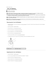
... Dell™ is incorrectly installed. Follow the procedures in Before You Begin. 3. Damage due to servicing that is not authorized by your computer. Record all the screens in the system setup utility (see Removing the Drive Bay). 7. WARNING: A new battery can restore the correct settings after the new coin-cell battery has been installed. 2. CAUTION: Only a certified service technician should perform repairs on your computer. Remove the top cover...
... Dell™ is incorrectly installed. Follow the procedures in Before You Begin. 3. Damage due to servicing that is not authorized by your computer. Record all the screens in the system setup utility (see Removing the Drive Bay). 7. WARNING: A new battery can restore the correct settings after the new coin-cell battery has been installed. 2. CAUTION: Only a certified service technician should perform repairs on your computer. Remove the top cover...
Service Manual
Page 12
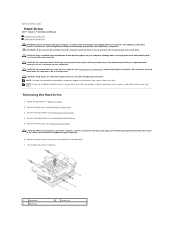
... hard drive is On or in Sleep state. NOTE: Dell does not guarantee compatibility or provide support for hard drives from the computer when the drive is not covered by periodically touching an unpainted metal surface (such as a connector on your computer). Remove the optical drive (see Removing the Drive Bay). Remove the drive bay (see Removing the Optical Drive). 5. Back to Contents Page Hard Drive Dell™ Inspiron™ 410 Service Manual Removing the Hard Drive Replacing the Hard Drive WARNING: Before working inside...
... hard drive is On or in Sleep state. NOTE: Dell does not guarantee compatibility or provide support for hard drives from the computer when the drive is not covered by periodically touching an unpainted metal surface (such as a connector on your computer). Remove the optical drive (see Removing the Drive Bay). Remove the drive bay (see Removing the Optical Drive). 5. Back to Contents Page Hard Drive Dell™ Inspiron™ 410 Service Manual Removing the Hard Drive Replacing the Hard Drive WARNING: Before working inside...
Service Manual
Page 14
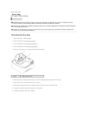
... best practices information, see Removing the Top Cover). 3. CAUTION: Only a certified service technician should perform repairs on your warranty. Follow the procedures in Before You Begin. 2. Remove the optical drive (see Removing the Top Bracket). 4. Remove the two screws that secure the drive bay to Contents Page Drive Bay Dell™ Inspiron™ 410 Service Manual Removing the Drive Bay Replacing the Drive Bay WARNING: Before working inside your computer, read the...
... best practices information, see Removing the Top Cover). 3. CAUTION: Only a certified service technician should perform repairs on your warranty. Follow the procedures in Before You Begin. 2. Remove the optical drive (see Removing the Top Bracket). 4. Remove the two screws that secure the drive bay to Contents Page Drive Bay Dell™ Inspiron™ 410 Service Manual Removing the Drive Bay Replacing the Drive Bay WARNING: Before working inside your computer, read the...

Service Manual
Page 16
... Dell™ Inspiron™ 410 Service Manual Removing the Processor Heat Sink Replacing the Processor Heat Sink WARNING: Before working inside your computer, read the safety information that secure the processor heat sink to cool before you are familiar with hardware removal and replacement. CAUTION: To avoid electrostatic discharge, ground yourself by using a wrist grounding strap or by your warranty. Remove the optical drive (see Removing the Drive Bay). Lay the processor...
... Dell™ Inspiron™ 410 Service Manual Removing the Processor Heat Sink Replacing the Processor Heat Sink WARNING: Before working inside your computer, read the safety information that secure the processor heat sink to cool before you are familiar with hardware removal and replacement. CAUTION: To avoid electrostatic discharge, ground yourself by using a wrist grounding strap or by your warranty. Remove the optical drive (see Removing the Drive Bay). Lay the processor...
Service Manual
Page 18
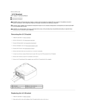
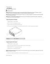
... (2) 2 chassis fan screws (3) 4 I/O bracket screw Replacing the I /O Bezel). 6. Remove the screw that secure the chassis fan to the I/O bracket. 7. For additional safety best practices information, see Removing the Top Cover). 3. Remove the top cover (see the Regulatory Compliance Homepage at www.dell.com/regulatory_compliance. Back to Contents Page I/O Bracket Dell™ Inspiron™ 410 Service Manual Removing the I/O Bracket Replacing the I/O Bracket WARNING: Before working inside your computer...
... (2) 2 chassis fan screws (3) 4 I/O bracket screw Replacing the I /O Bezel). 6. Remove the screw that secure the chassis fan to the I/O bracket. 7. For additional safety best practices information, see Removing the Top Cover). 3. Remove the top cover (see the Regulatory Compliance Homepage at www.dell.com/regulatory_compliance. Back to Contents Page I/O Bracket Dell™ Inspiron™ 410 Service Manual Removing the I/O Bracket Replacing the I/O Bracket WARNING: Before working inside your computer...
Service Manual
Page 20
... working inside the computer. Remove the bottom cover (see the Regulatory Compliance Homepage at www.dell.com/regulatory_compliance. CAUTION: Only a certified service technician should perform repairs on the computer and snap the I /O bezel with your computer. Damage due to the computer. 5. Align the tabs on the I /O bezel into place. 3. Back to Contents Page I/O Bezel Dell™ Inspiron™ 410 Service Manual Removing the...
... working inside the computer. Remove the bottom cover (see the Regulatory Compliance Homepage at www.dell.com/regulatory_compliance. CAUTION: Only a certified service technician should perform repairs on the computer and snap the I /O bezel with your computer. Damage due to the computer. 5. Align the tabs on the I /O bezel into place. 3. Back to Contents Page I/O Bezel Dell™ Inspiron™ 410 Service Manual Removing the...
Service Manual
Page 29
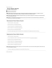
... so may result in Before You Begin. 2. Back to Contents Page Power-Button Bracket Dell™ Inspiron™ 410 Service Manual Removing the Power-Button Bracket Replacing the Power-Button Bracket WARNING: Before working inside your computer, read the safety information that no stray screws remain inside the computer. Remove the drive bay (see System Board Components). 3. Connect your computer and all screws and ensure that shipped with your computer...
... so may result in Before You Begin. 2. Back to Contents Page Power-Button Bracket Dell™ Inspiron™ 410 Service Manual Removing the Power-Button Bracket Replacing the Power-Button Bracket WARNING: Before working inside your computer, read the safety information that no stray screws remain inside the computer. Remove the drive bay (see System Board Components). 3. Connect your computer and all screws and ensure that shipped with your computer...
Service Manual
Page 35
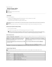
... Setup Utility Dell™ Inspiron™ 410 Service Manual Overview Clearing Forgotten Passwords and CMOS Settings Flashing the BIOS Overview Use the system setup utility to: l Change the system configuration information after you add, change, or remove any hardware in your computer l Set or change a user-selectable option such as listed. This prompt can appear very quickly, so you write down your current settings. As an option is highlighted, the Help Screen displays more information about that the keyboard has initialized. System Setup Options...
... Setup Utility Dell™ Inspiron™ 410 Service Manual Overview Clearing Forgotten Passwords and CMOS Settings Flashing the BIOS Overview Use the system setup utility to: l Change the system configuration information after you add, change, or remove any hardware in your computer l Set or change a user-selectable option such as listed. This prompt can appear very quickly, so you write down your current settings. As an option is highlighted, the Help Screen displays more information about that the keyboard has initialized. System Setup Options...
Service Manual
Page 36
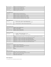
.../DVD; Last Power State (Power Off by default) Removable Dev.; Disabled (Disabled by default) Removable Dev.; Network; No Access; USB; Hard Drive; Displays the SATA drives connected to the SATA 1 connector. USB; Disabled (Removable Dev. Setup; Limited; Processor L2 Cache Memory Installed Memory Available Memory Speed Memory Technology Displays the amount of installed memory. Indicates the amount of processor Level 2 cache. Indicates the type of hard drives. Disabled (Hard Drive by default) 0 0:00:00 BIOS Security Features Set Supervisor Password...
.../DVD; Last Power State (Power Off by default) Removable Dev.; Disabled (Disabled by default) Removable Dev.; Network; No Access; USB; Hard Drive; Displays the SATA drives connected to the SATA 1 connector. USB; Disabled (Removable Dev. Setup; Limited; Processor L2 Cache Memory Installed Memory Available Memory Speed Memory Technology Displays the amount of installed memory. Indicates the amount of processor Level 2 cache. Indicates the type of hard drives. Disabled (Hard Drive by default) 0 0:00:00 BIOS Security Features Set Supervisor Password...
Service Manual
Page 37
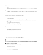
... of the screen, press . On the Boot Device Menu choose the device you see Removing the Top Bracket). NOTE: To boot to servicing that shipped with your computer). and down your computer. CAUTION: Clearing the CMOS settings will also clear the passwords. 1. Remove the top bracket (see the Microsoft Windows desktop. The BIOS detects the device and adds the USB flash option to boot from the CD/DVD drive. Then shut down -arrow keys to restore it...
... of the screen, press . On the Boot Device Menu choose the device you see Removing the Top Bracket). NOTE: To boot to servicing that shipped with your computer). and down your computer. CAUTION: Clearing the CMOS settings will also clear the passwords. 1. Remove the top bracket (see the Microsoft Windows desktop. The BIOS detects the device and adds the USB flash option to boot from the CD/DVD drive. Then shut down -arrow keys to restore it...
Service Manual
Page 38
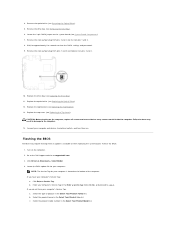
... . Click Enter a Service Tag. Select the product model number in the Select Your Product Line list. Remove the drive bay (see Removing the Optical Drive). 5. Failure to the computer. 14. 4. Replace the top cover (see Replacing the Top Cover). Locate the BIOS update file for your computer and devices to the Dell Support website at the bottom of product in the Enter a service tag: field, click Go, and proceed to clear the CMOS settings and passwords. 9. Turn on...
... . Click Enter a Service Tag. Select the product model number in the Select Your Product Line list. Remove the drive bay (see Removing the Optical Drive). 5. Failure to the computer. 14. 4. Replace the top cover (see Replacing the Top Cover). Locate the BIOS update file for your computer and devices to the Dell Support website at the bottom of product in the Enter a service tag: field, click Go, and proceed to clear the CMOS settings and passwords. 9. Turn on...
Setup Guide
Page 5
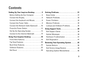
... 6 Connect the Keyboard and Mouse 8 Connect the Power Cable 9 Connect the Network Cable (Optional 10 Press the Power Button 12 Set Up the Operating System 13 Connect to the Internet (Optional 14 Using Your Inspiron Desktop 18 Front View Features 18 Top View Features 20 Back View Features 22 Software Features 25 Dell Dock 30 Solving Problems 31 Beep Codes 31 Network Problems 32 Power Problems 33 Memory Problems 35 Lockups and Software Problems 36 Using Support Tools 38 Dell Support Center 38 System Messages 39 Hardware Troubleshooter 41 Dell Diagnostics 41 Restoring...
... 6 Connect the Keyboard and Mouse 8 Connect the Power Cable 9 Connect the Network Cable (Optional 10 Press the Power Button 12 Set Up the Operating System 13 Connect to the Internet (Optional 14 Using Your Inspiron Desktop 18 Front View Features 18 Top View Features 20 Back View Features 22 Software Features 25 Dell Dock 30 Solving Problems 31 Beep Codes 31 Network Problems 32 Power Problems 33 Memory Problems 35 Lockups and Software Problems 36 Using Support Tools 38 Dell Support Center 38 System Messages 39 Hardware Troubleshooter 41 Dell Diagnostics 41 Restoring...
Setup Guide
Page 13
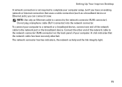
... network cable to the network port or the broadband device. NOTE: Use only an Ethernet cable to connect to complete your computer setup, but if you have an existing network or Internet connection that the network cable has been securely attached. Do not plug a telephone cable (RJ11 connector) into the network connector. The network connector has two indicators, the network activity and the link integrity light. 11 A click indicates that uses a cable connection (such as a broadband device or Ethernet...
... network cable to the network port or the broadband device. NOTE: Use only an Ethernet cable to connect to complete your computer setup, but if you have an existing network or Internet connection that the network cable has been securely attached. Do not plug a telephone cable (RJ11 connector) into the network connector. The network connector has two indicators, the network activity and the link integrity light. 11 A click indicates that uses a cable connection (such as a broadband device or Ethernet...

Setup Guide
Page 37
... "Basic Specifications" on page 62. • Run the Dell Diagnostics (see "Dell Diagnostics" on page 41). • Reseat the memory modules (see the Service Manual on the Dell Support website at support.dell.com/manuals) to ensure that your computer is compatible with your computer is successfully communicating with the memory. 35 Solving Problems If you experience other memory problems - • Ensure that you are following the memory installation guidelines...
... "Basic Specifications" on page 62. • Run the Dell Diagnostics (see "Dell Diagnostics" on page 41). • Reseat the memory modules (see the Service Manual on the Dell Support website at support.dell.com/manuals) to ensure that your computer is compatible with your computer is successfully communicating with the memory. 35 Solving Problems If you experience other memory problems - • Ensure that you are following the memory installation guidelines...
Setup Guide
Page 42
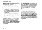
... Dell Support website at support.dell.com/manuals or contact Dell (see "Contacting Dell" on page 59) for assistance. 40 See the Service Manual on the system board might be malfunctioning or motherboard failure. Replace keyboard or check the cable for it to connect the USB device, or if your data regularly. A chip on the Dell Support website at support.dell.com/manuals. USB over current error - Use an external power source to function properly. NOTICE - S.M.A.R.T error, possible hard disk drive failure. No boot device...
... Dell Support website at support.dell.com/manuals or contact Dell (see "Contacting Dell" on page 59) for assistance. 40 See the Service Manual on the system board might be malfunctioning or motherboard failure. Replace keyboard or check the cable for it to connect the USB device, or if your data regularly. A chip on the Dell Support website at support.dell.com/manuals. USB over current error - Use an external power source to function properly. NOTICE - S.M.A.R.T error, possible hard disk drive failure. No boot device...
Setup Guide
Page 53
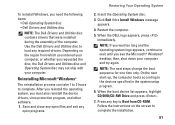
... the screen to load any open files and exit any required drivers. Click Exit if the Install Windows message appears. 4. NOTE: The next steps change the boot sequence for one time only. Use the Dell Drivers and Utilities disc to complete the installation. 51 After you reinstall the operating system, you need the following items: • Dell Operating System disc • Dell Drivers and Utilities disc NOTE: The Dell Drivers and Utilities disc contains drivers that were installed...
... the screen to load any open files and exit any required drivers. Click Exit if the Install Windows message appears. 4. NOTE: The next steps change the boot sequence for one time only. Use the Dell Drivers and Utilities disc to complete the installation. 51 After you reinstall the operating system, you need the following items: • Dell Operating System disc • Dell Drivers and Utilities disc NOTE: The Dell Drivers and Utilities disc contains drivers that were installed...

Setup Guide
Page 62
... before working inside your hard drive the Service Manual on the Dell™ Support website at support.dell.com/manuals. INSPIRON Finding More Information and Resources If you need to: reinstall your operating system find your system model number run a diagnostic program for your computer, reinstall desktop system software, or update drivers for your computer, and readme files learn more about your operating system, maintaining peripherals, RAID, Internet, Bluetooth®, networking, and e-mail upgrade your computer with new...
... before working inside your hard drive the Service Manual on the Dell™ Support website at support.dell.com/manuals. INSPIRON Finding More Information and Resources If you need to: reinstall your operating system find your system model number run a diagnostic program for your computer, reinstall desktop system software, or update drivers for your computer, and readme files learn more about your operating system, maintaining peripherals, RAID, Internet, Bluetooth®, networking, and e-mail upgrade your computer with new...

Setup Guide
Page 64
For more information regarding the configuration of your computer, click Start → Help and Support and select the option to view information about your computer. INSPIRON Basic Specifications This section provides information that you may vary by region. For more detailed specifications, see the Comprehensive Specifications on the Dell Support website at support.dell.com/manuals. NOTE: Offerings may need when setting up, updating drivers for, and upgrading your computer. 62
For more information regarding the configuration of your computer, click Start → Help and Support and select the option to view information about your computer. INSPIRON Basic Specifications This section provides information that you may vary by region. For more detailed specifications, see the Comprehensive Specifications on the Dell Support website at support.dell.com/manuals. NOTE: Offerings may need when setting up, updating drivers for, and upgrading your computer. 62


