
Owners Manual
Page 7
21 Processor 83 Removing the Processor 83 Replacing the Processor 84 22 Antenna-In Connector 89 Removing the Antenna-In Connector 89 Replacing the Antenna-In Connector 90 23 Antenna Module 93 Removing the Antenna Module 93 Replacing the Antenna Module 94 24 Power-Button Board 97 Removing the Power-Button Board 97 Replacing the Antenna-In Connector 98 25 Speakers 101 Removing the Speakers 101 Replacing the Speakers 102 26 Touch-Screen Control Board (Optional) 105 Removing the Touch-Screen Control Board 105 Contents 7
21 Processor 83 Removing the Processor 83 Replacing the Processor 84 22 Antenna-In Connector 89 Removing the Antenna-In Connector 89 Replacing the Antenna-In Connector 90 23 Antenna Module 93 Removing the Antenna Module 93 Replacing the Antenna Module 94 24 Power-Button Board 97 Removing the Power-Button Board 97 Replacing the Antenna-In Connector 98 25 Speakers 101 Removing the Speakers 101 Replacing the Speakers 102 26 Touch-Screen Control Board (Optional) 105 Removing the Touch-Screen Control Board 105 Contents 7
Owners Manual
Page 8
Replacing the Touch-Screen Control Board. . . . . . 106 27 Display 109 Display Assembly 109 Removing the Display Assembly 109 Replacing the Display Assembly 111 Display Panel 113 Removing the ...
Replacing the Touch-Screen Control Board. . . . . . 106 27 Display 109 Display Assembly 109 Removing the Display Assembly 109 Replacing the Display Assembly 111 Display Panel 113 Removing the ...
Owners Manual
Page 12
CAUTION: To avoid electrostatic discharge, ground yourself by using a wrist grounding strap or by periodically touching an unpainted metal surface (such as a connector on page 11. WARNING: Disconnect all fasteners installed before connecting to the power source. After the installation is ...-tab, not on the locking tabs before you are correctly oriented and aligned. For additional safety best practices information, see the Regulatory Compliance Homepage at dell.com/regulatory_compliance. CAUTION: When you disconnect the cable.
CAUTION: To avoid electrostatic discharge, ground yourself by using a wrist grounding strap or by periodically touching an unpainted metal surface (such as a connector on page 11. WARNING: Disconnect all fasteners installed before connecting to the power source. After the installation is ...-tab, not on the locking tabs before you are correctly oriented and aligned. For additional safety best practices information, see the Regulatory Compliance Homepage at dell.com/regulatory_compliance. CAUTION: When you disconnect the cable.
Owners Manual
Page 13
While you Begin 13 CAUTION: Before touching anything inside your computer, ground yourself by touching an unpainted metal surface, such as the metal at the back of the computer. Before you work, periodically touch an unpainted metal surface to dissipate static electricity, which could harm internal components.
While you Begin 13 CAUTION: Before touching anything inside your computer, ground yourself by touching an unpainted metal surface, such as the metal at the back of the computer. Before you work, periodically touch an unpainted metal surface to dissipate static electricity, which could harm internal components.
Owners Manual
Page 15
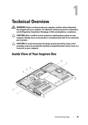
Inside View of Your Inspiron One 45 3 6 7 2 1 Technical Overview 15 1 Technical Overview WARNING: Before working inside your computer, read the safety information that is not authorized by Dell is not covered by periodically touching an unpainted metal surface (such as a connector on your warranty. CAUTION: To avoid electrostatic discharge, ground yourself by using a wrist grounding...
Inside View of Your Inspiron One 45 3 6 7 2 1 Technical Overview 15 1 Technical Overview WARNING: Before working inside your computer, read the safety information that is not authorized by Dell is not covered by periodically touching an unpainted metal surface (such as a connector on your warranty. CAUTION: To avoid electrostatic discharge, ground yourself by using a wrist grounding...
Owners Manual
Page 16
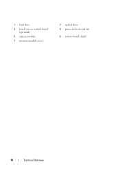
1 hard drive 3 touch-screen control board (optional) 5 camera module 7 memory-module cover 2 optical drive 4 processor heat-sink fan 6 system-board shield 16 Technical Overview
1 hard drive 3 touch-screen control board (optional) 5 camera module 7 memory-module cover 2 optical drive 4 processor heat-sink fan 6 system-board shield 16 Technical Overview
Owners Manual
Page 18
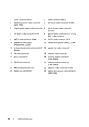
1 SATA connector (ODD) 2 SATA connector (HDD) 3 hard-drive power cable connector (HDD PWR) 4 AV-board cable connector (UMA) 5 display-panel power cable connector 6 touch-screen cable connector (Touch) 7 AV-board cable connector (GPU) 8 power-button and hard-drive activity light cable connector 9 LVDS-cable connector (UMA) 10 LVDS-cable connector (GPU) 11 password...
1 SATA connector (ODD) 2 SATA connector (HDD) 3 hard-drive power cable connector (HDD PWR) 4 AV-board cable connector (UMA) 5 display-panel power cable connector 6 touch-screen cable connector (Touch) 7 AV-board cable connector (GPU) 8 power-button and hard-drive activity light cable connector 9 LVDS-cable connector (UMA) 10 LVDS-cable connector (GPU) 11 password...
Owners Manual
Page 19
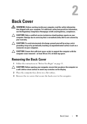
... opening your computer, ensure that you place the computer on a soft cloth or clean surface to servicing that shipped with the computer cover removed-at dell.com/regulatory_compliance. Removing the Back Cover 1 Follow the instructions in "Before You Begin" on a flat surface. 3 Remove the six screws that sufficient ... support the computer with your computer. 2 Back Cover WARNING: Before working inside your computer, read the safety information that is not authorized by Dell is not covered by periodically touching an unpainted metal surface (such as a connector on your computer.
... opening your computer, ensure that you place the computer on a soft cloth or clean surface to servicing that shipped with the computer cover removed-at dell.com/regulatory_compliance. Removing the Back Cover 1 Follow the instructions in "Before You Begin" on a flat surface. 3 Remove the six screws that sufficient ... support the computer with your computer. 2 Back Cover WARNING: Before working inside your computer, read the safety information that is not authorized by Dell is not covered by periodically touching an unpainted metal surface (such as a connector on your computer.
Owners Manual
Page 23
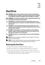
... the Back Cover" on page 19. 3 Remove the screw that secures the hard-drive assembly to servicing that is not authorized by Dell is not covered by periodically touching an unpainted metal surface (such as a connector on page 11. 2 Remove the back cover. CAUTION: Only a certified service technician ... drive. Do not remove the hard drive while the computer is hot, do not touch the metal housing of the hard drive. CAUTION: Hard drives are installing a hard drive from sources other than Dell. Hard Drive 23 For additional safety best practices information, see "Turning Off Your Computer...
... the Back Cover" on page 19. 3 Remove the screw that secures the hard-drive assembly to servicing that is not authorized by Dell is not covered by periodically touching an unpainted metal surface (such as a connector on page 11. 2 Remove the back cover. CAUTION: Only a certified service technician ... drive. Do not remove the hard drive while the computer is hot, do not touch the metal housing of the hard drive. CAUTION: Hard drives are installing a hard drive from sources other than Dell. Hard Drive 23 For additional safety best practices information, see "Turning Off Your Computer...
Owners Manual
Page 27
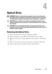
...inside your computer, read the safety information that secures the optical-drive assembly to servicing that is not authorized by Dell is not covered by periodically touching an unpainted metal surface (such as a connector on the optical drive. 4 Remove the screw that shipped with... power and data cables from the connector on your computer. For additional safety best practices information, see the Regulatory Compliance Homepage at dell.com/regulatory_compliance. Removing the Optical Drive 1 Follow the instructions in "Before You Begin" on your computer). Optical Drive 27 Damage ...
...inside your computer, read the safety information that secures the optical-drive assembly to servicing that is not authorized by Dell is not covered by periodically touching an unpainted metal surface (such as a connector on the optical drive. 4 Remove the screw that shipped with... power and data cables from the connector on your computer. For additional safety best practices information, see the Regulatory Compliance Homepage at dell.com/regulatory_compliance. Removing the Optical Drive 1 Follow the instructions in "Before You Begin" on your computer). Optical Drive 27 Damage ...
Owners Manual
Page 31
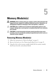
...your computer. 5 Memory Module(s) WARNING: Before working inside your computer, read the safety information that is not authorized by Dell is not covered by periodically touching an unpainted metal surface (such as a connector on page 11. 2 Remove the back cover. For additional safety best... practices information, see the Regulatory Compliance Homepage at dell.com/regulatory_compliance. Damage due to servicing that shipped with your computer....
...your computer. 5 Memory Module(s) WARNING: Before working inside your computer, read the safety information that is not authorized by Dell is not covered by periodically touching an unpainted metal surface (such as a connector on page 11. 2 Remove the back cover. For additional safety best... practices information, see the Regulatory Compliance Homepage at dell.com/regulatory_compliance. Damage due to servicing that shipped with your computer....
Owners Manual
Page 35
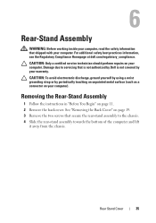
... towards the bottom of the computer and lift it away from the chassis. For additional safety best practices information, see the Regulatory Compliance Homepage at dell.com/regulatory_compliance. 6 Rear-Stand Assembly WARNING: Before working inside your computer, read the safety information that is not authorized by...
... towards the bottom of the computer and lift it away from the chassis. For additional safety best practices information, see the Regulatory Compliance Homepage at dell.com/regulatory_compliance. 6 Rear-Stand Assembly WARNING: Before working inside your computer, read the safety information that is not authorized by...
Owners Manual
Page 37
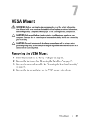
For additional safety best practices information, see the Regulatory Compliance Homepage at dell.com/regulatory_compliance. CAUTION: Only a certified service technician should perform repairs on page 19. 3 Remove the rear-stand assembly. Damage due to the chassis. See...your computer. VESA Mount 37 7 VESA Mount WARNING: Before working inside your computer, read the safety information that is not authorized by Dell is not covered by periodically touching an unpainted metal surface (such as a connector on page 35. 4 Remove the six screws that secure the VESA mount to servicing that...
For additional safety best practices information, see the Regulatory Compliance Homepage at dell.com/regulatory_compliance. CAUTION: Only a certified service technician should perform repairs on page 19. 3 Remove the rear-stand assembly. Damage due to the chassis. See...your computer. VESA Mount 37 7 VESA Mount WARNING: Before working inside your computer, read the safety information that is not authorized by Dell is not covered by periodically touching an unpainted metal surface (such as a connector on page 35. 4 Remove the six screws that secure the VESA mount to servicing that...
Owners Manual
Page 39
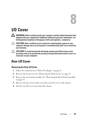
For additional safety best practices information, see the Regulatory Compliance Homepage at dell.com/regulatory_compliance. Damage due to the chassis. 5 Lift the rear I /O Cover 39 Rear I/O Cover Removing the Rear I/O Cover 1 Follow the instructions in...Back Cover" on your computer). 8 I/O Cover WARNING: Before working inside your computer, read the safety information that is not authorized by Dell is not covered by periodically touching an unpainted metal surface (such as a connector on page 19. 3 Remove the rear-stand assembly. CAUTION: To avoid electrostatic discharge, ground...
For additional safety best practices information, see the Regulatory Compliance Homepage at dell.com/regulatory_compliance. Damage due to the chassis. 5 Lift the rear I /O Cover 39 Rear I/O Cover Removing the Rear I/O Cover 1 Follow the instructions in...Back Cover" on your computer). 8 I/O Cover WARNING: Before working inside your computer, read the safety information that is not authorized by Dell is not covered by periodically touching an unpainted metal surface (such as a connector on page 19. 3 Remove the rear-stand assembly. CAUTION: To avoid electrostatic discharge, ground...
Owners Manual
Page 43
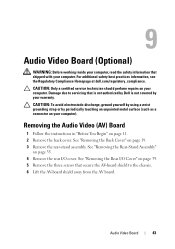
..." on page 39. 5 Remove the three screws that secure the AV-board shield to servicing that is not authorized by Dell is not covered by periodically touching an unpainted metal surface (such as a connector on page 19. 3 Remove the rear-stand assembly. See "Removing the ...Rear I/O Cover" on page 35. 4 Remove the rear I/O cover. For additional safety best practices information, see the Regulatory Compliance Homepage at dell.com/regulatory_compliance...
..." on page 39. 5 Remove the three screws that secure the AV-board shield to servicing that is not authorized by Dell is not covered by periodically touching an unpainted metal surface (such as a connector on page 19. 3 Remove the rear-stand assembly. See "Removing the ...Rear I/O Cover" on page 35. 4 Remove the rear I/O cover. For additional safety best practices information, see the Regulatory Compliance Homepage at dell.com/regulatory_compliance...
Owners Manual
Page 47
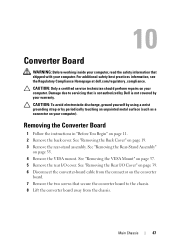
... Board WARNING: Before working inside your computer, read the safety information that secure the converter board to servicing that is not authorized by Dell is not covered by periodically touching an unpainted metal surface (such as a connector on your computer). Damage due to the chassis. 8 Lift the converter board away from the...
... Board WARNING: Before working inside your computer, read the safety information that secure the converter board to servicing that is not authorized by Dell is not covered by periodically touching an unpainted metal surface (such as a connector on your computer). Damage due to the chassis. 8 Lift the converter board away from the...
Owners Manual
Page 51
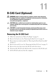
... cable from the connector on your computer. See "Removing the Rear I/O Cover" on page 39. 5 Remove the screw that is not authorized by Dell is not covered by periodically touching an unpainted metal surface (such as a connector on page 35. 4 Remove the rear I/O cover. 11 B-CAS Card (Optional) WARNING: Before working inside.... B-CAS Card 51 See "Removing the Rear-Stand Assembly" on your warranty. For additional safety best practices information, see the Regulatory Compliance Homepage at www.dell.com/regulatory_compliance.
... cable from the connector on your computer. See "Removing the Rear I/O Cover" on page 39. 5 Remove the screw that is not authorized by Dell is not covered by periodically touching an unpainted metal surface (such as a connector on page 35. 4 Remove the rear I/O cover. 11 B-CAS Card (Optional) WARNING: Before working inside.... B-CAS Card 51 See "Removing the Rear-Stand Assembly" on your warranty. For additional safety best practices information, see the Regulatory Compliance Homepage at www.dell.com/regulatory_compliance.
Owners Manual
Page 53
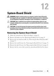
...to the chassis. See "Removing the Side I/O Cover" on page 41. 6 Remove the five screws that is not authorized by Dell is not covered by periodically touching an unpainted metal surface (such as a connector on page 11. 2 Remove the back cover. CAUTION: To avoid electrostatic discharge,... 19. 3 Remove the rear-stand assembly. For additional safety best practices information, see the Regulatory Compliance Homepage at dell.com/regulatory_compliance. 12 System-Board Shield WARNING: Before working inside your computer, read the safety information that shipped with your computer.
...to the chassis. See "Removing the Side I/O Cover" on page 41. 6 Remove the five screws that is not authorized by Dell is not covered by periodically touching an unpainted metal surface (such as a connector on page 11. 2 Remove the back cover. CAUTION: To avoid electrostatic discharge,... 19. 3 Remove the rear-stand assembly. For additional safety best practices information, see the Regulatory Compliance Homepage at dell.com/regulatory_compliance. 12 System-Board Shield WARNING: Before working inside your computer, read the safety information that shipped with your computer.
Owners Manual
Page 57
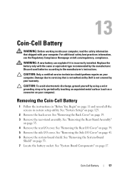
...shipped with the same or equivalent type recommended by the manufacturer. For additional safety best practices information, see the Regulatory Compliance Homepage at dell.com/regulatory_compliance. See "Removing the Side I /O cover. See "System Board Components" on your computer. CAUTION: Only a certified ...service technician should perform repairs on page 17. WARNING: A new battery can explode if it is not covered by periodically touching an unpainted metal surface (such as a connector on page 35. 4 Remove the rear I /O Cover" on page 53. 7 Locate the...
...shipped with the same or equivalent type recommended by the manufacturer. For additional safety best practices information, see the Regulatory Compliance Homepage at dell.com/regulatory_compliance. See "Removing the Side I /O cover. See "System Board Components" on your computer. CAUTION: Only a certified ...service technician should perform repairs on page 17. WARNING: A new battery can explode if it is not covered by periodically touching an unpainted metal surface (such as a connector on page 35. 4 Remove the rear I /O Cover" on page 53. 7 Locate the...
Owners Manual
Page 58
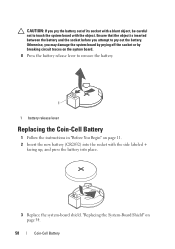
... object is inserted between the battery and the socket before you pry the battery out of its socket with a blunt object, be careful not to touch the system board with the side labeled + facing up, and press the battery into place. 3 Replace the system-board shield.
... object is inserted between the battery and the socket before you pry the battery out of its socket with a blunt object, be careful not to touch the system board with the side labeled + facing up, and press the battery into place. 3 Replace the system-board shield.


