Service Manual
Page 5
... the Display Cable 49 Display-Panel Brackets 50 Removing the Display-Panel Brackets 50 Replacing the Display-Panel Brackets 50 11 Hinge Cover 53 Removing the Hinge Cover 53 Replacing the Hinge Cover 55 12 Camera Module 57 Removing the Camera Module 57 Replacing the Camera Module 58 13 Coin-Cell Battery 61...
... the Display Cable 49 Display-Panel Brackets 50 Removing the Display-Panel Brackets 50 Replacing the Display-Panel Brackets 50 11 Hinge Cover 53 Removing the Hinge Cover 53 Replacing the Hinge Cover 55 12 Camera Module 57 Removing the Camera Module 57 Replacing the Camera Module 58 13 Coin-Cell Battery 61...
Service Manual
Page 53
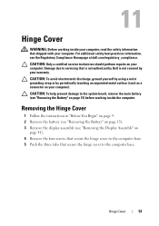
... on your warranty. Removing the Hinge Cover 1 Follow the instructions in "Before You Begin" on page 9. 2 Remove the battery (see "Removing the Battery" on page 15). 3 Remove the display assembly (see the Regulatory Compliance Homepage at dell.com/regulatory_compliance. For additional safety... best practices information, see "Removing the Display Assembly" on page 41). 4 Remove the four screws that secure the hinge cover to the computer base. 5 Push the three ...
... on your warranty. Removing the Hinge Cover 1 Follow the instructions in "Before You Begin" on page 9. 2 Remove the battery (see "Removing the Battery" on page 15). 3 Remove the display assembly (see the Regulatory Compliance Homepage at dell.com/regulatory_compliance. For additional safety... best practices information, see "Removing the Display Assembly" on page 41). 4 Remove the four screws that secure the hinge cover to the computer base. 5 Push the three ...
Service Manual
Page 54
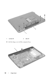
2 1 1 screws (4) 2 tabs (7) 6 Lift the hinge cover off the computer base. 1 54 Hinge Cover
2 1 1 screws (4) 2 tabs (7) 6 Lift the hinge cover off the computer base. 1 54 Hinge Cover
Service Manual
Page 55
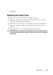
... "Before You Begin" on page 9. 2 Align the seven tabs on the hinge cover with the slots on the computer base and snap the hinge cover into place. 3 Replace the four screws that secure the hinge cover to the computer. 1 Hinge Cover Replacing the Hinge Cover 1 Follow the instructions in damage to the computer base. 4 Replace...
... "Before You Begin" on page 9. 2 Align the seven tabs on the hinge cover with the slots on the computer base and snap the hinge cover into place. 3 Replace the four screws that secure the hinge cover to the computer. 1 Hinge Cover Replacing the Hinge Cover 1 Follow the instructions in damage to the computer base. 4 Replace...

Service Manual
Page 56
56 Hinge Cover
56 Hinge Cover

Service Manual
Page 65
... the system board, remove the main battery (see "Removing the Battery" on page 41). 9 Remove the hinge cover (see the Regulatory Compliance Homepage at dell.com/regulatory_compliance. 14 System Board WARNING: Before working inside your computer, read the safety information that is not ...authorized by Dell is not covered by your computer). For additional safety best practices information, see "Removing the Hinge Cover" on your computer. CAUTION: To avoid electrostatic discharge, ground yourself by using ...
... the system board, remove the main battery (see "Removing the Battery" on page 41). 9 Remove the hinge cover (see the Regulatory Compliance Homepage at dell.com/regulatory_compliance. 14 System Board WARNING: Before working inside your computer, read the safety information that is not ...authorized by Dell is not covered by your computer). For additional safety best practices information, see "Removing the Hinge Cover" on your computer. CAUTION: To avoid electrostatic discharge, ground yourself by using ...
Service Manual
Page 67
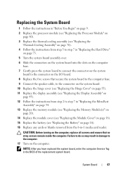
... that secure the system board to the computer base. 9 Connect the speaker cable, to the connector on the system board. 10 Replace the hinge cover (see "Replacing the Hinge Cover" on page 55). 11 Replace the display assembly (see "Replacing the Display Assembly" on page 43). 12 Follow the instructions from step...
... that secure the system board to the computer base. 9 Connect the speaker cable, to the connector on the system board. 10 Replace the hinge cover (see "Replacing the Hinge Cover" on page 55). 11 Replace the display assembly (see "Replacing the Display Assembly" on page 43). 12 Follow the instructions from step...
Service Manual
Page 83
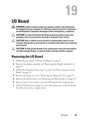
...Assembly" on page 41). 3 Follow the instructions from step 2 to step 12 in "Removing the System Board" on page 65. 4 Remove the hinge cover (see "Removing the Hinge Cover" on page 53). 5 Remove the Mini-Card(s) (see "Removing the Mini-Card(s)" on page 37). 6 Remove the two screws that ...secure the I/O board to the computer base. 7 Lift the I/O board at dell.com/regulatory_compliance. Damage due to remove the connectors on the I /O Board 83 19 ...
...Assembly" on page 41). 3 Follow the instructions from step 2 to step 12 in "Removing the System Board" on page 65. 4 Remove the hinge cover (see "Removing the Hinge Cover" on page 53). 5 Remove the Mini-Card(s) (see "Removing the Mini-Card(s)" on page 37). 6 Remove the two screws that ...secure the I/O board to the computer base. 7 Lift the I/O board at dell.com/regulatory_compliance. Damage due to remove the connectors on the I /O Board 83 19 ...
Service Manual
Page 84
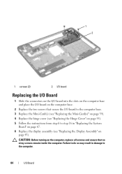
... to do so may result in damage to step 16 in "Replacing the System Board" on page 67. 6 Replace the display assembly (see "Replacing the Hinge Cover" on page 55). 5 Follow the instructions from step 6 to the computer. 84 I/O Board 1 2 1 screws (2) 2 I/O board Replacing the I/O Board 1 Slide the connectors on the I/O board... screws and ensure that secure the I/O board to the computer base. 3 Replace the Mini-Card(s) (see "Replacing the Mini-Card(s)" on page 39). 4 Replace the hinge cover (see "Replacing the Display Assembly" on page 43).
... to do so may result in damage to step 16 in "Replacing the System Board" on page 67. 6 Replace the display assembly (see "Replacing the Hinge Cover" on page 55). 5 Follow the instructions from step 6 to the computer. 84 I/O Board 1 2 1 screws (2) 2 I/O board Replacing the I/O Board 1 Slide the connectors on the I/O board... screws and ensure that secure the I/O board to the computer base. 3 Replace the Mini-Card(s) (see "Replacing the Mini-Card(s)" on page 39). 4 Replace the hinge cover (see "Replacing the Display Assembly" on page 43).
Service Manual
Page 85
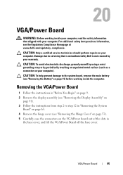
Damage due to step 12 in "Removing the System Board" on page 65. 4 Remove the hinge cover (see the Regulatory Compliance Homepage at www.dell.com/regulatory_compliance. CAUTION: Only a certified service technician should perform repairs on the VGA/Power board out of the slots in the base cover, and lift ...
Damage due to step 12 in "Removing the System Board" on page 65. 4 Remove the hinge cover (see the Regulatory Compliance Homepage at www.dell.com/regulatory_compliance. CAUTION: Only a certified service technician should perform repairs on the VGA/Power board out of the slots in the base cover, and lift ...
Service Manual
Page 86
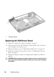
...Board Replacing the VGA/Power Board 1 Follow the instructions in "Replacing the System Board" on page 67. 5 Replace the display assembly (see "Replacing the Hinge Cover" on page 55). 4 Follow the instructions from step 6 to the computer. 86 VGA/Power Board Failure to do so may result in damage to...9. 2 Align the connectors on the VGA/Power board with the slots on the base cover and place it on the base cover. 3 Replace the hinge cover (see "Replacing the Display Assembly" on the computer, replace all screws and ensure that no stray screws remain inside the computer. CAUTION: Before ...
...Board Replacing the VGA/Power Board 1 Follow the instructions in "Replacing the System Board" on page 67. 5 Replace the display assembly (see "Replacing the Hinge Cover" on page 55). 4 Follow the instructions from step 6 to the computer. 86 VGA/Power Board Failure to do so may result in damage to...9. 2 Align the connectors on the VGA/Power board with the slots on the base cover and place it on the base cover. 3 Replace the hinge cover (see "Replacing the Display Assembly" on the computer, replace all screws and ensure that no stray screws remain inside the computer. CAUTION: Before ...


