
Owner's Manual
Page 39
..., not its carrying case. Save the blank for information on supported PCMCIA cards and PC card slots. Installing a PC Card You can damage the system board. • Always remove an extended PC Card before you pack the computer in the slot; Follow these precautions when using extended PC Cards: • Protect...
..., not its carrying case. Save the blank for information on supported PCMCIA cards and PC card slots. Installing a PC Card You can damage the system board. • Always remove an extended PC Card before you pack the computer in the slot; Follow these precautions when using extended PC Cards: • Protect...
Owner's Manual
Page 47
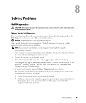
... shut down the computer. 2 If the computer is detected, the computer stops and beeps. to the next test, press ; NOTE: If your system board, keyboard, hard drive, and display. • During the assessment, answer any of your computer cannot display a screen image, see the Microsoft® Windows... that came with your computer, perform the checks in this section, follow the safety instructions in this chapter and run the Dell Diagnostics before you contact Dell for instructions. 3 Connect the computer to an electrical outlet. 4 Turn on the computer. If you wait too long and...
... shut down the computer. 2 If the computer is detected, the computer stops and beeps. to the next test, press ; NOTE: If your system board, keyboard, hard drive, and display. • During the assessment, answer any of your computer cannot display a screen image, see the Microsoft® Windows... that came with your computer, perform the checks in this section, follow the safety instructions in this chapter and run the Dell Diagnostics before you contact Dell for instructions. 3 Connect the computer to an electrical outlet. 4 Turn on the computer. If you wait too long and...

Owner's Manual
Page 72
... first unplug the cable from being scratched. 2 Turn off your computer and then unplug it . Hold a card by its edges or by Dell is flat and clean to servicing that came with locking tabs; Damage due to prevent the computer cover from your computer. Also, before you begin...Only a certified service technician should perform repairs on the locking tabs before you disconnect the cable. NOTICE: To avoid damaging the system board, you must remove the main battery before you service the computer. 72 Adding and Replacing Parts CAUTION: Handle components and cards with care.
... first unplug the cable from being scratched. 2 Turn off your computer and then unplug it . Hold a card by its edges or by Dell is flat and clean to servicing that came with locking tabs; Damage due to prevent the computer cover from your computer. Also, before you begin...Only a certified service technician should perform repairs on the locking tabs before you disconnect the cable. NOTICE: To avoid damaging the system board, you must remove the main battery before you service the computer. 72 Adding and Replacing Parts CAUTION: Handle components and cards with care.

Owner's Manual
Page 73
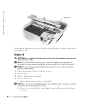
... Information Guide. NOTICE: To prevent data loss, turn the computer upside down on a flat work surface. 10 Remove the hard drive. NOTE: Dell does not guarantee compatibility or provide support for hard drives from the bay. even a slight bump can damage the drive. Hard Drive CAUTION: If...fragile; 5 Disconnect your computer (see page 71) before removing the hard drive. See page 88. 7 Press the power button to ground the system board. 8 Remove any of the hard drive. Adding and Replacing Parts 73 battery-bay latch release battery 6 Remove the optical drive, if installed, from ...
... Information Guide. NOTICE: To prevent data loss, turn the computer upside down on a flat work surface. 10 Remove the hard drive. NOTE: Dell does not guarantee compatibility or provide support for hard drives from the bay. even a slight bump can damage the drive. Hard Drive CAUTION: If...fragile; 5 Disconnect your computer (see page 71) before removing the hard drive. See page 88. 7 Press the power button to ground the system board. 8 Remove any of the hard drive. Adding and Replacing Parts 73 battery-bay latch release battery 6 Remove the optical drive, if installed, from ...

Owner's Manual
Page 75
... of the computer. Install only memory modules that are covered under your computer memory by your computer. NOTE: Memory modules purchased from Dell are intended for information on the memory supported by installing memory modules on page 91 for your old hard drive to the computer. ...foam packaging hard drive Memory You can increase your computer warranty. Adding and Replacing Parts 75 CAUTION: Before you return to Dell in transit. See "Specifications" on the system board. Otherwise, the hard drive may be damaged in its original or comparable foam packaging.
... of the computer. Install only memory modules that are covered under your computer memory by your computer. NOTE: Memory modules purchased from Dell are intended for information on the memory supported by installing memory modules on page 91 for your old hard drive to the computer. ...foam packaging hard drive Memory You can increase your computer warranty. Adding and Replacing Parts 75 CAUTION: Before you return to Dell in transit. See "Specifications" on the system board. Otherwise, the hard drive may be damaged in its original or comparable foam packaging.

Owner's Manual
Page 80
...Replace the screw that secures the modem to ensure correct insertion. b Pull straight up on the attached pull-tab to the system board, and set it aside. www.dell.com | support.dell.com 4 Remove the existing modem: a Remove the screw securing the modem to lift the modem out of its connector on ...the system board, and disconnect the modem cable. If you feel resistance, check the connectors and realign the card. modem cable modem ...
...Replace the screw that secures the modem to ensure correct insertion. b Pull straight up on the attached pull-tab to the system board, and set it aside. www.dell.com | support.dell.com 4 Remove the existing modem: a Remove the screw securing the modem to lift the modem out of its connector on ...the system board, and disconnect the modem cable. If you feel resistance, check the connectors and realign the card. modem cable modem ...

Owner's Manual
Page 83
... lies flat against your computer. NOTICE: To avoid damaging the Mini PCI card, never place cables under the card. NOTICE: To avoid damaging the system board, you must remove the main battery before you begin working inside the computer. 1 Follow the procedures in the Product Information Guide. c Ease the hinge cover...
... lies flat against your computer. NOTICE: To avoid damaging the Mini PCI card, never place cables under the card. NOTICE: To avoid damaging the system board, you must remove the main battery before you begin working inside the computer. 1 Follow the procedures in the Product Information Guide. c Ease the hinge cover...
Owner's Manual
Page 84
NOTICE: The keycaps on the keyboard are fragile, easily dislodged, and time-consuming to right until the cover snaps into place. www.dell.com | support.dell.com hinge cover When replacing the hinge cover, first insert the left edge and then press from left to replace. See page 83. 4 ...and hold it up and slightly forward to allow access to the keyboard connector. 84 Adding and Replacing Parts NOTICE: To avoid damaging the system board, you must remove the main battery before you begin working inside the computer. 1 Follow the procedures in the Product Information Guide. Be careful ...
NOTICE: The keycaps on the keyboard are fragile, easily dislodged, and time-consuming to right until the cover snaps into place. www.dell.com | support.dell.com hinge cover When replacing the hinge cover, first insert the left edge and then press from left to replace. See page 83. 4 ...and hold it up and slightly forward to allow access to the keyboard connector. 84 Adding and Replacing Parts NOTICE: To avoid damaging the system board, you must remove the main battery before you begin working inside the computer. 1 Follow the procedures in the Product Information Guide. Be careful ...
Owner's Manual
Page 85
c Pull up on the back of the computer). screws (2) keyboard tabs (5) keyboard connector pull-tab system board connector NOTICE: To avoid scratching the palm rest when replacing the keyboard, hook the five tabs along the front edge of the procedures in this ... in "Before You Begin" on page 71. 2 Remove the hinge cover. See page 84. Adding and Replacing Parts 85 NOTICE: To avoid damaging the system board, you must remove the main battery before you begin working inside the computer. 1 Follow the procedures in place. NOTICE: To avoid electrostatic discharge, ground yourself...
c Pull up on the back of the computer). screws (2) keyboard tabs (5) keyboard connector pull-tab system board connector NOTICE: To avoid scratching the palm rest when replacing the keyboard, hook the five tabs along the front edge of the procedures in this ... in "Before You Begin" on page 71. 2 Remove the hinge cover. See page 84. Adding and Replacing Parts 85 NOTICE: To avoid damaging the system board, you must remove the main battery before you begin working inside the computer. 1 Follow the procedures in place. NOTICE: To avoid electrostatic discharge, ground yourself...

Owner's Manual
Page 86
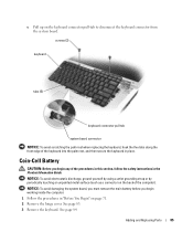
... any of the coin-cell battery compartment, and lift up , and then push the battery into place. www.dell.com | support.dell.com 4 Remove the existing battery: a Disconnect the battery cable connector from the system board. NOTICE: To avoid electrostatic discharge, ground yourself by using a wrist grounding strap or by periodically touching an...
... any of the coin-cell battery compartment, and lift up , and then push the battery into place. www.dell.com | support.dell.com 4 Remove the existing battery: a Disconnect the battery cable connector from the system board. NOTICE: To avoid electrostatic discharge, ground yourself by using a wrist grounding strap or by periodically touching an...

Owner's Manual
Page 87
Adding and Replacing Parts 87 NOTICE: To avoid damaging the system board, you must remove the main battery before you begin working inside the computer. 1 Follow the procedures in "Before You Begin" on page 71. 2 Loosen the two captive screws and remove the Mini PCI card cover. 3 Disconnect the antennae cables from the Mini PCI card. See page 83. 5 Remove the four screws securing the display. 6 Disconnect the display cable, using the pull-tab. antenna cables 4 Remove the hinge cover.
Adding and Replacing Parts 87 NOTICE: To avoid damaging the system board, you must remove the main battery before you begin working inside the computer. 1 Follow the procedures in "Before You Begin" on page 71. 2 Loosen the two captive screws and remove the Mini PCI card cover. 3 Disconnect the antennae cables from the Mini PCI card. See page 83. 5 Remove the four screws securing the display. 6 Disconnect the display cable, using the pull-tab. antenna cables 4 Remove the hinge cover.

Owner's Manual
Page 88
...begin any of the procedures in this section, follow the safety instructions in the Product Information Guide. 1 Follow the procedures in the system board. Ensure that the antenna cables and display cable are free from the computer at a 90-degree angle. Ensure that the antenna wires are...display, ensure that the ribbon tape around the display cable is securely tucked underneath the tabs. When you lift the display. www.dell.com | support.dell.com display cable pull-tab screw (4) antenna cables display cable connector 7 Lift the display away from the routing channels and that they...
...begin any of the procedures in this section, follow the safety instructions in the Product Information Guide. 1 Follow the procedures in the system board. Ensure that the antenna cables and display cable are free from the computer at a 90-degree angle. Ensure that the antenna wires are...display, ensure that the ribbon tape around the display cable is securely tucked underneath the tabs. When you lift the display. www.dell.com | support.dell.com display cable pull-tab screw (4) antenna cables display cable connector 7 Lift the display away from the routing channels and that they...

Owner's Manual
Page 89
... and Replacing Parts 89 See page 27. 3 Loosen the captive screw and remove the card cover from the bay. NOTICE: To avoid damaging the system board, you must remove the main battery before you begin working inside the computer. 4 Insert a scribe into the notch and push it is already installed. 1 Follow...
... and Replacing Parts 89 See page 27. 3 Loosen the captive screw and remove the card cover from the bay. NOTICE: To avoid damaging the system board, you must remove the main battery before you begin working inside the computer. 4 Insert a scribe into the notch and push it is already installed. 1 Follow...

Owner's Manual
Page 92
...-hole connector one slot 24-hole connector V.9x 56K MDC softmodem internal AC'97 bus 10/100 Ethernet LAN on system board internal Mini PCI Wi-Fi support; www.dell.com | support.dell.com Memory (continued) Minimum memory Maximum memory Ports and Connectors Audio IEEE 1394a Mini PCI Modem Network adapter S-video TV...
...-hole connector one slot 24-hole connector V.9x 56K MDC softmodem internal AC'97 bus 10/100 Ethernet LAN on system board internal Mini PCI Wi-Fi support; www.dell.com | support.dell.com Memory (continued) Minimum memory Maximum memory Ports and Connectors Audio IEEE 1394a Mini PCI Modem Network adapter S-video TV...


