
Owner's Manual
Page 6
... Problems 63 Video and Display Problems 64 If the display is blank 64 If the display is difficult to read 65 If only part of the display is readable 65 Drivers 66 What Is a Driver 66 Identifying Drivers 66 Reinstalling Drivers 66 Restoring Your Operating System ...67 Using Microsoft Windows XP System Restore 68 Using Dell PC Restore by Symantec 69 Resolving Software and Hardware Incompatibilities 70 9 Adding and Replacing Parts Before You Begin 71 Recommended Tools 71 Turning Off Your Computer 71 Before Working Inside Your...
... Problems 63 Video and Display Problems 64 If the display is blank 64 If the display is difficult to read 65 If only part of the display is readable 65 Drivers 66 What Is a Driver 66 Identifying Drivers 66 Reinstalling Drivers 66 Restoring Your Operating System ...67 Using Microsoft Windows XP System Restore 68 Using Dell PC Restore by Symantec 69 Resolving Software and Hardware Incompatibilities 70 9 Adding and Replacing Parts Before You Begin 71 Recommended Tools 71 Turning Off Your Computer 71 Before Working Inside Your...

Owner's Manual
Page 48
... successfully, you cannot resolve the error condition, contact Dell. If you receive the message Booting Dell Diagnostic Utility Partition. See "Contacting Dell" on page 99. Dell Diagnostics Main Menu 1 After the Dell Diagnostics loads and the Main Menu screen appears, click the button for your part. See "Contacting Dell" on page 99. Write down the error code...
... successfully, you cannot resolve the error condition, contact Dell. If you receive the message Booting Dell Diagnostic Utility Partition. See "Contacting Dell" on page 99. Dell Diagnostics Main Menu 1 After the Dell Diagnostics loads and the Main Menu screen appears, click the button for your part. See "Contacting Dell" on page 99. Write down the error code...

Owner's Manual
Page 65
...the monitor brightness and contrast controls. If the display is plugged into an electrical outlet. If only part of the display is at least 60 cm (2 ft) away from the computer or external monitor. ... the Start button and then click Control Panel. 2 Click Appearance and Themes. 3 Click the area you want to the computer. 2 Turn on page 99. Contact Dell. M O V E T H E E X T E R N A L S U B W O O F E R A W A Y F R O M T H E C O M P U T E R O R M O N I O N - If the external monitor works, the computer display or video controller may be defective. E L I M I N A T E P O S S I B L E I G H T N...
...the monitor brightness and contrast controls. If the display is plugged into an electrical outlet. If only part of the display is at least 60 cm (2 ft) away from the computer or external monitor. ... the Start button and then click Control Panel. 2 Click Appearance and Themes. 3 Click the area you want to the computer. 2 Turn on page 99. Contact Dell. M O V E T H E E X T E R N A L S U B W O O F E R A W A Y F R O M T H E C O M P U T E R O R M O N I O N - If the external monitor works, the computer display or video controller may be defective. E L I M I N A T E P O S S I B L E I G H T N...

Owner's Manual
Page 71
... the following tools: • Small flat-blade screwdriver • Phillips screwdriver • Small plastic scribe • Flash BIOS update program (see the Dell Support website at least 8-10 seconds until the computer turns off your computer. b In the Turn off computer window, click Turn off . Adding and...and exit any open programs, click the Start button, and then click Turn Off Computer. Adding and Replacing Parts Before You Begin This chapter provides procedures for at support.dell.com) Turning Off Your Computer NOTICE: To avoid losing data, save and close any open files, exit ...
... the following tools: • Small flat-blade screwdriver • Phillips screwdriver • Small plastic scribe • Flash BIOS update program (see the Dell Support website at least 8-10 seconds until the computer turns off your computer. b In the Turn off computer window, click Turn off . Adding and...and exit any open programs, click the Start button, and then click Turn Off Computer. Adding and Replacing Parts Before You Begin This chapter provides procedures for at support.dell.com) Turning Off Your Computer NOTICE: To avoid losing data, save and close any open files, exit ...

Owner's Manual
Page 72
... ensure your computer. NOTICE: To avoid damaging the system board, you must remove the main battery before you service the computer. 72 Adding and Replacing Parts Hold a component such as a processor by its edges, not by its strain-relief loop, not on a card. Some cables have a connector with... servicing that came with locking tabs; See page 71. 3 If the computer is not covered by its metal mounting bracket. www.dell.com | support.dell.com Before Working Inside Your Computer Use the following steps before you begin any of the procedures in this type of cable, press ...
... ensure your computer. NOTICE: To avoid damaging the system board, you must remove the main battery before you service the computer. 72 Adding and Replacing Parts Hold a component such as a processor by its edges, not by its strain-relief loop, not on a card. Some cables have a connector with... servicing that came with locking tabs; See page 71. 3 If the computer is not covered by its metal mounting bracket. www.dell.com | support.dell.com Before Working Inside Your Computer Use the following steps before you begin any of the procedures in this type of cable, press ...

Owner's Manual
Page 73
... hot, do not touch the metal housing of the hard drive. even a slight bump can damage the drive. Adding and Replacing Parts 73 NOTICE: Hard drives are extremely fragile; NOTE: Dell does not guarantee compatibility or provide support for hard drives from the optical drive bay. Hard Drive CAUTION: If you begin... your computer (see page 71) before removing the hard drive. battery-bay latch release battery 6 Remove the optical drive, if installed, from sources other than Dell.
... hot, do not touch the metal housing of the hard drive. even a slight bump can damage the drive. Adding and Replacing Parts 73 NOTICE: Hard drives are extremely fragile; NOTE: Dell does not guarantee compatibility or provide support for hard drives from the optical drive bay. Hard Drive CAUTION: If you begin... your computer (see page 71) before removing the hard drive. battery-bay latch release battery 6 Remove the optical drive, if installed, from sources other than Dell.

Owner's Manual
Page 74
...your computer. 74 Adding and Replacing Parts To replace the hard drive in the hard drive bay: 1 Follow the procedures in protective antistatic packaging. If you use excessive force, you may damage the connector. 5 Slide the hard drive into place. www.dell.com | support.dell.com NOTE: If you are installing...Electrostatic Discharge" in the Product Information Guide. 3 Slide the hard drive out of the computer. 4 Remove the new drive from a source other than Dell, you need to slide the drive into the bay until it is fully seated. 6 Replace and tighten the screws. 7 If the new hard drive ...
...your computer. 74 Adding and Replacing Parts To replace the hard drive in the hard drive bay: 1 Follow the procedures in protective antistatic packaging. If you use excessive force, you may damage the connector. 5 Slide the hard drive into place. www.dell.com | support.dell.com NOTE: If you are installing...Electrostatic Discharge" in the Product Information Guide. 3 Slide the hard drive out of the computer. 4 Remove the new drive from a source other than Dell, you need to slide the drive into the bay until it is fully seated. 6 Replace and tighten the screws. 7 If the new hard drive ...

Owner's Manual
Page 75
Adding and Replacing Parts 75 NOTE: If you leave the area, ground yourself again when you begin...connectors on the back of the computer. See "Specifications" on the system board. NOTE: Memory modules purchased from Dell are intended for information on the memory supported by installing memory modules on page 91 for your computer. Install ... that are covered under your computer memory by your computer. CAUTION: Before you return to Dell in transit. Returning a Hard Drive to Dell Return your old hard drive to the computer. Otherwise, the hard drive may be damaged in...
Adding and Replacing Parts 75 NOTE: If you leave the area, ground yourself again when you begin...connectors on the back of the computer. See "Specifications" on the system board. NOTE: Memory modules purchased from Dell are intended for information on the memory supported by installing memory modules on page 91 for your computer. Install ... that are covered under your computer memory by your computer. CAUTION: Before you return to Dell in transit. Returning a Hard Drive to Dell Return your old hard drive to the computer. Otherwise, the hard drive may be damaged in...

Owner's Manual
Page 76
www.dell.com | support.dell.com 3 Turn the computer over, loosen the captive screws on each end of the memory module connector until the module pops up. b Remove the module from the connector. 76 Adding and Replacing Parts NOTICE: To prevent damage to the memory module connector, do not use tools to spread the memorymodule securing clips. 4 If you are replacing a memory module, remove the existing module: a Use your fingertips to carefully spread apart the securing clips on the memory module cover, and then remove the cover.
www.dell.com | support.dell.com 3 Turn the computer over, loosen the captive screws on each end of the memory module connector until the module pops up. b Remove the module from the connector. 76 Adding and Replacing Parts NOTICE: To prevent damage to the memory module connector, do not use tools to spread the memorymodule securing clips. 4 If you are replacing a memory module, remove the existing module: a Use your fingertips to carefully spread apart the securing clips on the memory module cover, and then remove the cover.

Owner's Manual
Page 77
... and install the new memory module: a Align the notch in the module edge connector with the tab in the connector labeled "DIMMB." Adding and Replacing Parts 77 Insert memory modules at a 45-degree angle, and rotate the module down until it . NOTE: If the memory module is not installed properly, the...
... and install the new memory module: a Align the notch in the module edge connector with the tab in the connector labeled "DIMMB." Adding and Replacing Parts 77 Insert memory modules at a 45-degree angle, and rotate the module down until it . NOTE: If the memory module is not installed properly, the...

Owner's Manual
Page 78
NOTICE: If the cover is difficult to close , remove the module and reinstall it. www.dell.com | support.dell.com 6 Replace the memory module cover. Forcing the cover to close may damage your computer. 78 Adding and Replacing Parts
NOTICE: If the cover is difficult to close , remove the module and reinstall it. www.dell.com | support.dell.com 6 Replace the memory module cover. Forcing the cover to close may damage your computer. 78 Adding and Replacing Parts

Owner's Manual
Page 79
... electrical outlet. 8 Reinstall the hard drive. Modem CAUTION: Before you begin any of memory installed in "Before You Begin" on the computer. Adding and Replacing Parts 79 If prompted, press to your finger under the cover at the indentation and lift the cover open. 7 Insert the battery into the battery bay...
... electrical outlet. 8 Reinstall the hard drive. Modem CAUTION: Before you begin any of memory installed in "Before You Begin" on the computer. Adding and Replacing Parts 79 If prompted, press to your finger under the cover at the indentation and lift the cover open. 7 Insert the battery into the battery bay...

Owner's Manual
Page 80
... the connectors and realign the card. c Replace the screw that secures the modem to the system board, and set it aside. www.dell.com | support.dell.com 4 Remove the existing modem: a Remove the screw securing the modem to the system board. 6 Replace the modem cover. 80 Adding... and Replacing Parts modem cable modem pull-tab screw system board connector 5 Install the replacement modem: a Connect the modem cable to ensure correct insertion....
... the connectors and realign the card. c Replace the screw that secures the modem to the system board, and set it aside. www.dell.com | support.dell.com 4 Remove the existing modem: a Remove the screw securing the modem to the system board. 6 Replace the modem cover. 80 Adding... and Replacing Parts modem cable modem pull-tab screw system board connector 5 Install the replacement modem: a Connect the modem cable to ensure correct insertion....

Owner's Manual
Page 81
... your finger under the cover at the indentation and lift the cover open. 4 If a Mini PCI card is already installed. antenna cables Adding and Replacing Parts 81 If you are replacing a Mini PCI card, remove the existing card: a Disconnect the antenna cables from the modem cover. 3 Place your computer, the card...
... your finger under the cover at the indentation and lift the cover open. 4 If a Mini PCI card is already installed. antenna cables Adding and Replacing Parts 81 If you are replacing a Mini PCI card, remove the existing card: a Disconnect the antenna cables from the modem cover. 3 Place your computer, the card...

Owner's Manual
Page 82
If you feel resistance, check the connectors and realign the card. 5 Install the replacement Mini PCI card: a Align the Mini PCI card with the connector at a 45-degree angle, and press the Mini PCI card into the connector until the card pops up slightly. Mini PCI card metal securing tabs (2) NOTICE: The connectors are keyed to ensure correct insertion. www.dell.com | support.dell.com b Release the Mini PCI card by spreading the metal securing tabs until it clicks. 82 Adding and Replacing Parts c Lift the Mini PCI card out of its connector.
If you feel resistance, check the connectors and realign the card. 5 Install the replacement Mini PCI card: a Align the Mini PCI card with the connector at a 45-degree angle, and press the Mini PCI card into the connector until the card pops up slightly. Mini PCI card metal securing tabs (2) NOTICE: The connectors are keyed to ensure correct insertion. www.dell.com | support.dell.com b Release the Mini PCI card by spreading the metal securing tabs until it clicks. 82 Adding and Replacing Parts c Lift the Mini PCI card out of its connector.

Owner's Manual
Page 83
..." on the right side. c Ease the hinge cover up, moving from right to left, and remove it lies flat against your computer. Adding and Replacing Parts 83 b Connect the antenna cables to lift the hinge cover on page 71. 2 Remove the hinge cover.: a Open the display all the way (180 degrees...
..." on the right side. c Ease the hinge cover up, moving from right to left, and remove it lies flat against your computer. Adding and Replacing Parts 83 b Connect the antenna cables to lift the hinge cover on page 71. 2 Remove the hinge cover.: a Open the display all the way (180 degrees...
Owner's Manual
Page 84
... yourself by using a wrist grounding strap or by periodically touching an unpainted metal surface (such as a connector on the back of the keyboard. www.dell.com | support.dell.com hinge cover When replacing the hinge cover, first insert the left edge and then press from left to the keyboard connector. 84 Adding...
... yourself by using a wrist grounding strap or by periodically touching an unpainted metal surface (such as a connector on the back of the keyboard. www.dell.com | support.dell.com hinge cover When replacing the hinge cover, first insert the left edge and then press from left to the keyboard connector. 84 Adding...
Owner's Manual
Page 85
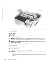
... inside the computer. 1 Follow the procedures in place. c Pull up on the back of the computer). See page 83. 3 Remove the keyboard. Adding and Replacing Parts 85 screws (2) keyboard tabs (5) keyboard connector pull-tab system board connector NOTICE: To avoid scratching the palm rest when replacing the keyboard, hook the five...
... inside the computer. 1 Follow the procedures in place. c Pull up on the back of the computer). See page 83. 3 Remove the keyboard. Adding and Replacing Parts 85 screws (2) keyboard tabs (5) keyboard connector pull-tab system board connector NOTICE: To avoid scratching the palm rest when replacing the keyboard, hook the five...

Owner's Manual
Page 86
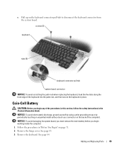
... as a connector on the back of the procedures in this section, follow the safety instructions in the Product Information Guide. www.dell.com | support.dell.com 4 Remove the existing battery: a Disconnect the battery cable connector from the system board. Display CAUTION: Before you begin any... of the computer). 86 Adding and Replacing Parts b Press the release latch on the system board. 6 Replace the keyboard. 7 Replace the hinge cover. ...
... as a connector on the back of the procedures in this section, follow the safety instructions in the Product Information Guide. www.dell.com | support.dell.com 4 Remove the existing battery: a Disconnect the battery cable connector from the system board. Display CAUTION: Before you begin any... of the computer). 86 Adding and Replacing Parts b Press the release latch on the system board. 6 Replace the keyboard. 7 Replace the hinge cover. ...

Owner's Manual
Page 87
antenna cables 4 Remove the hinge cover. NOTICE: To avoid damaging the system board, you must remove the main battery before you begin working inside the computer. 1 Follow the procedures in "Before You Begin" on page 71. 2 Loosen the two captive screws and remove the Mini PCI card cover. 3 Disconnect the antennae cables from the Mini PCI card. Adding and Replacing Parts 87 See page 83. 5 Remove the four screws securing the display. 6 Disconnect the display cable, using the pull-tab.
antenna cables 4 Remove the hinge cover. NOTICE: To avoid damaging the system board, you must remove the main battery before you begin working inside the computer. 1 Follow the procedures in "Before You Begin" on page 71. 2 Loosen the two captive screws and remove the Mini PCI card cover. 3 Disconnect the antennae cables from the Mini PCI card. Adding and Replacing Parts 87 See page 83. 5 Remove the four screws securing the display. 6 Disconnect the display cable, using the pull-tab.


