
Owners Manual
Page 6
... Reinstalling Drivers for Windows XP 71 Restoring Your Operating System 71 Using Microsoft Windows XP System Restore 71 Using Dell PC Restore by Symantec 73 Resolving Software and Hardware Incompatibilities 74 8 Adding and Replacing Parts Adding Memory 77 Adding a Mini PCI Card 81 Adding a Modem 84 Replacing the Hard Drive 87 6 Contents
... Reinstalling Drivers for Windows XP 71 Restoring Your Operating System 71 Using Microsoft Windows XP System Restore 71 Using Dell PC Restore by Symantec 73 Resolving Software and Hardware Incompatibilities 74 8 Adding and Replacing Parts Adding Memory 77 Adding a Mini PCI Card 81 Adding a Modem 84 Replacing the Hard Drive 87 6 Contents

Owners Manual
Page 10
...Documentation for my computer • Documentation for devices (such as memory, the hard drive, and the operating system • Customer Care - Upgrade information for components, such as a modem) Find it Here Dell Support Website - Troubleshooting hints and tips, articles from technicians, and... information, order status, warranty, and repair information • Downloads - support.dell.com NOTE: Select your problem. 4 Follow the instructions on the screen. 10 Finding Information www.dell.com | support.dell.com What Are You Looking For? • Latest drivers for my computer ...
...Documentation for my computer • Documentation for devices (such as memory, the hard drive, and the operating system • Customer Care - Upgrade information for components, such as a modem) Find it Here Dell Support Website - Troubleshooting hints and tips, articles from technicians, and... information, order status, warranty, and repair information • Downloads - support.dell.com NOTE: Select your problem. 4 Follow the instructions on the screen. 10 Finding Information www.dell.com | support.dell.com What Are You Looking For? • Latest drivers for my computer ...

Owners Manual
Page 20
www.dell.com | support.dell.com Bottom View battery-bay latch release hard drive Mini PCI card/modem cover battery battery charge gauge docking device slot fan memory module cover B A T T E R Y - Releases the battery. B A T T E R Y - See page 30. F A N - CAUTION: Do not block, push objects into, or allow dust to ...T E R Y C H A R G E G A U G E - D O C K I N G D E V I C A R D A N D M O D E M - H A R D D R I V E - Fan noise is normal and does not indicate a problem with your computer in the air vents. Covers the compartment that contains the memory modules.
www.dell.com | support.dell.com Bottom View battery-bay latch release hard drive Mini PCI card/modem cover battery battery charge gauge docking device slot fan memory module cover B A T T E R Y - Releases the battery. B A T T E R Y - See page 30. F A N - CAUTION: Do not block, push objects into, or allow dust to ...T E R Y C H A R G E G A U G E - D O C K I N G D E V I C A R D A N D M O D E M - H A R D D R I V E - Fan noise is normal and does not indicate a problem with your computer in the air vents. Covers the compartment that contains the memory modules.

Owners Manual
Page 31
... low or depleted. If the battery temperature is on the computer. Bypass power protection devices, power strips, and the extension cable to charge. See the Dell Inspiron help file, see page 77). C H E C K T H E A C A D A P T E R - If the light is too hot to verify that the computer turns on. ...the AC adapter to connect the computer to an electrical outlet. 3 Turn on but the display remains blank, reseat the memory modules (see page 61. Contact Dell (see page 26), disconnect the computer from the electrical outlet, and then let the battery and computer cool to turn ...
... low or depleted. If the battery temperature is on the computer. Bypass power protection devices, power strips, and the extension cable to charge. See the Dell Inspiron help file, see page 77). C H E C K T H E A C A D A P T E R - If the light is too hot to verify that the computer turns on. ...the AC adapter to connect the computer to an electrical outlet. 3 Turn on but the display remains blank, reseat the memory modules (see page 61. Contact Dell (see page 26), disconnect the computer from the electrical outlet, and then let the battery and computer cool to turn ...
Owners Manual
Page 61
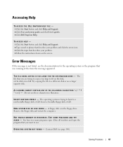
...appeared. Insert a bootable floppy disk or CD. A floppy disk is too full. EXIT SOME PROGRAMS AND TRY A G A I V E - Accessing Help TO ACCESS THE DELL INSPIRON HELP FILE - 1 Click the Start button and click Help and Support. 2 Click User and system guides and click User's guides. 3 Click...all windows and open . Solving Problems 61 A FILENAME CANNOT CONTAIN ANY OF THE FOLLOWING CHARACTERS Do not use a larger capacity disk. NOT ENOUGH MEMORY OR RESOURCES. Try copying the file to a nonbootable floppy disk or CD. You have too many programs open the program that describes your problem ...
...appeared. Insert a bootable floppy disk or CD. A floppy disk is too full. EXIT SOME PROGRAMS AND TRY A G A I V E - Accessing Help TO ACCESS THE DELL INSPIRON HELP FILE - 1 Click the Start button and click Help and Support. 2 Click User and system guides and click User's guides. 3 Click...all windows and open . Solving Problems 61 A FILENAME CANNOT CONTAIN ANY OF THE FOLLOWING CHARACTERS Do not use a larger capacity disk. NOT ENOUGH MEMORY OR RESOURCES. Try copying the file to a nonbootable floppy disk or CD. You have too many programs open the program that describes your problem ...

Owners Manual
Page 68
...that the computer is working properly. Let the computer dry for at least 24 hours in a dry area at room temperature. www.dell.com | support.dell.com 8 Remove the memory module(s) (see page 77). 9 Open the display and place the computer right-side up across two books or similar props to ...speed the drying process. If the computer does not start , or if you cannot identify the damaged components, contact Dell (see page 100). 68...
...that the computer is working properly. Let the computer dry for at least 24 hours in a dry area at room temperature. www.dell.com | support.dell.com 8 Remove the memory module(s) (see page 77). 9 Open the display and place the computer right-side up across two books or similar props to ...speed the drying process. If the computer does not start , or if you cannot identify the damaged components, contact Dell (see page 100). 68...

Owners Manual
Page 77
... device for instructions. 4 Disconnect the computer from Dell are intended for information on the system board. See the documentation that came with your computer, follow the safety instructions located in this procedure. NOTE: Memory modules purchased from the electrical outlet. 5 Wait ...Remove any open files, exit any installed PC Cards, batteries, and module bay devices. Adding Memory You can increase your computer memory by installing memory modules on the memory supported by your computer warranty. NOTICE: Handle components and cards by touching a metal connector on ...
... device for instructions. 4 Disconnect the computer from Dell are intended for information on the system board. See the documentation that came with your computer, follow the safety instructions located in this procedure. NOTE: Memory modules purchased from the electrical outlet. 5 Wait ...Remove any open files, exit any installed PC Cards, batteries, and module bay devices. Adding Memory You can increase your computer memory by installing memory modules on the memory supported by your computer warranty. NOTICE: Handle components and cards by touching a metal connector on ...

Owners Manual
Page 78
captive screw memory module cover NOTICE: To prevent damage to the memory module connector, do not use tools to spread the memory-module securing clips. 78 Adding and Replacing Parts www.dell.com | support.dell.com 7 Turn the computer over, loosen the captive screw from the memory module cover, and then remove the cover.
captive screw memory module cover NOTICE: To prevent damage to the memory module connector, do not use tools to spread the memory-module securing clips. 78 Adding and Replacing Parts www.dell.com | support.dell.com 7 Turn the computer over, loosen the captive screw from the memory module cover, and then remove the cover.

Owners Manual
Page 79
b Remove the module from the connector. securing clips (2 per connector) memory module NOTICE: If you need to install memory modules in two connectors, install a memory module in the connector labeled "DIMM A" before you are replacing a memory module, remove the existing module: a Use your fingertips to avoid damaging the connector. Insert memory modules at a 45-degree angle to carefully spread apart the securing clips on each end of the memory module connector until the module pops up. Adding and Replacing Parts 79 8 If you install a module in the connector labeled "DIMM B."
b Remove the module from the connector. securing clips (2 per connector) memory module NOTICE: If you need to install memory modules in two connectors, install a memory module in the connector labeled "DIMM A" before you are replacing a memory module, remove the existing module: a Use your fingertips to avoid damaging the connector. Insert memory modules at a 45-degree angle to carefully spread apart the securing clips on each end of the memory module connector until the module pops up. Adding and Replacing Parts 79 8 If you install a module in the connector labeled "DIMM B."

Owners Manual
Page 80
..., outer edge. a Align the notch in the module edge connector with the tab in the connector slot. www.dell.com | support.dell.com 9 Ground yourself and install the new memory module: NOTE: If the memory module is not installed properly, the computer may not boot properly. NOTICE: Only hold the module by the shorter...
..., outer edge. a Align the notch in the module edge connector with the tab in the connector slot. www.dell.com | support.dell.com 9 Ground yourself and install the new memory module: NOTE: If the memory module is not installed properly, the computer may not boot properly. NOTICE: Only hold the module by the shorter...

Owners Manual
Page 81
... user. CAUTION: Before working inside your computer, follow the instructions noted below. As the computer boots, it . To confirm the amount of memory installed in the computer, click the Start button, click Help and Support, and then click Computer Information. NOTE: 2.4 GHz Wireless LAN PC...Dell service personnel are removing and/or installing a 2.4 GHz (802.11b, 802.11b/g) Mini PCI Card, please follow the safety instructions located in your portable computer may be purchased only from installing 5 GHz (802.11a,802.11a/b, 802.11a/b/g) Wireless LAN Mini PCI cards. captive screw memory...
... user. CAUTION: Before working inside your computer, follow the instructions noted below. As the computer boots, it . To confirm the amount of memory installed in the computer, click the Start button, click Help and Support, and then click Computer Information. NOTE: 2.4 GHz Wireless LAN PC...Dell service personnel are removing and/or installing a 2.4 GHz (802.11b, 802.11b/g) Mini PCI Card, please follow the safety instructions located in your portable computer may be purchased only from installing 5 GHz (802.11a,802.11a/b, 802.11a/b/g) Wireless LAN Mini PCI cards. captive screw memory...

Owners Manual
Page 91
Video Video type Data bus Video controller Video memory LCD interface TV support Audio Audio type Stereo conversion Interfaces: Internal External Speaker Internal speaker amplifier Volume controls 32-bit hardware accelerated (NVIDIA GeForce FX ...
Video Video type Data bus Video controller Video memory LCD interface TV support Audio Audio type Stereo conversion Interfaces: Internal External Speaker Internal speaker amplifier Volume controls 32-bit hardware accelerated (NVIDIA GeForce FX ...

Owners Manual
Page 95
... to write down the information for example, your computer password. • To verify information about the computer's current configuration, such as the amount of system memory. After you system configuration information and optional settings. Environmental Temperature range: Operating Storage Relative humidity (maximum): Operating Storage Maximum vibration (using a random-vibration spectrum that...
... to write down the information for example, your computer password. • To verify information about the computer's current configuration, such as the amount of system memory. After you system configuration information and optional settings. Environmental Temperature range: Operating Storage Relative humidity (maximum): Operating Storage Maximum vibration (using a random-vibration spectrum that...

Owners Manual
Page 120
... description, 14 system view, 14 keypad numeric, 39 L labels Microsoft Windows, 9 Service Tag, 9 line conditioners, 25 M memory adding, 77 removing, 79 Microsoft Windows label, 9 Mini PCI card installing, 81 Mini PCI card, modem, and memory module cover description, 20 system view, 20 modem adding, 84 modem connector description, 19 system view, 19...
... description, 14 system view, 14 keypad numeric, 39 L labels Microsoft Windows, 9 Service Tag, 9 line conditioners, 25 M memory adding, 77 removing, 79 Microsoft Windows label, 9 Mini PCI card installing, 81 Mini PCI card, modem, and memory module cover description, 20 system view, 20 modem adding, 84 modem connector description, 19 system view, 19...

Owners Manual
Page 121
See memory reinstalling drivers, 70 Windows XP, 71 S security cable slot description, 16-17 system view, 16-17 Service Tag, 9 Setup Diagram, 9 shutting down your computer, 26 ...
See memory reinstalling drivers, 70 Windows XP, 71 S security cable slot description, 16-17 system view, 16-17 Service Tag, 9 Setup Diagram, 9 shutting down your computer, 26 ...


