
Service Manual
Page 16
... CAUTION: Ensure that shipped with your computer. For more information, see System Board Components. 1 screws (4) 2 power cable 3 data cable 4 SATA connector (on your computer model. Replace the computer cover (see Removing the Computer Cover). 3. Remove the four screws securing the hard drive. 5....changes in Before You Begin. 2. Connect the computer and other end of the computer. 6. Back to Contents Page Drives Dell™ Inspiron™ 535/537/545/546 Service Manual Removing a Hard Drive Replacing a Hard Drive Removing a Media Card Reader Replacing a Media Card Reader Removing...
... CAUTION: Ensure that shipped with your computer. For more information, see System Board Components. 1 screws (4) 2 power cable 3 data cable 4 SATA connector (on your computer model. Replace the computer cover (see Removing the Computer Cover). 3. Remove the four screws securing the hard drive. 5....changes in Before You Begin. 2. Connect the computer and other end of the computer. 6. Back to Contents Page Drives Dell™ Inspiron™ 535/537/545/546 Service Manual Removing a Hard Drive Replacing a Hard Drive Removing a Media Card Reader Replacing a Media Card Reader Removing...

Service Manual
Page 19
... the Front Bezel). 4. Remove the bezel (see Replacing the Front Bezel). 8. Slide the optical drive out through the front of SATA connectors may vary based on . Replace the computer cover (see Removing the Computer Cover). 3. Follow the procedures in the optical drive...drive operation. 11. For more information, see System Board Components. 1 power cable 2 data cable 3 optical drive 4 custom screws (2) 5 SATA connector (on installing any software required for drive configuration changes (see System Setup Options). Replace the bezel (see Replacing the Computer Cover). 10....
... the Front Bezel). 4. Remove the bezel (see Replacing the Front Bezel). 8. Slide the optical drive out through the front of SATA connectors may vary based on . Replace the computer cover (see Removing the Computer Cover). 3. Follow the procedures in the optical drive...drive operation. 11. For more information, see System Board Components. 1 power cable 2 data cable 3 optical drive 4 custom screws (2) 5 SATA connector (on installing any software required for drive configuration changes (see System Setup Options). Replace the bezel (see Replacing the Computer Cover). 10....

Service Manual
Page 32
... device priority of CD/DVD drives. USB; Disabled (Removable Dev. CD/DVD; Low Speed (High Speed by default) Onboard SATA Controller Enabled or Disabled (Enabled by default) Onboard AUDIO Controller Enabled or Disabled (Enabled by default) Onboard LAN Controller Enabled or... Disabled (Enabled by default) Second Boot Device Removable Dev.; On (On by default) Module Bay Identifies the device installed in Inspiron 537 Integrated Peripherals USB Device Setting l USB Controller-Enabled or Disabled (Enabled by default) Boot Other Device Enabled; The items ...
... device priority of CD/DVD drives. USB; Disabled (Removable Dev. CD/DVD; Low Speed (High Speed by default) Onboard SATA Controller Enabled or Disabled (Enabled by default) Onboard AUDIO Controller Enabled or Disabled (Enabled by default) Onboard LAN Controller Enabled or... Disabled (Enabled by default) Second Boot Device Removable Dev.; On (On by default) Module Bay Identifies the device installed in Inspiron 537 Integrated Peripherals USB Device Setting l USB Controller-Enabled or Disabled (Enabled by default) Boot Other Device Enabled; The items ...
Service Manual
Page 33
...of hard drives. Displays the SATA drives connected to the SATA 5 connector. Disabled (Enabled by default) Set Supervisor Password Supervisor Password Installed; Boot Device Configuration Hard Disk Boot Priority Used to change the user password Inspiron 545 System Info System BIOS Info ...Removable; Remote Wake Up Auto Power On Auto Power On Date Auto Power On Time AC Recovery On; Displays the SATA drives connected to the SATA 4 connector. Disable (Enabled by default) Advanced Chipset Features Init Display First PCI Slot, Onboard (PCI Slot by ...
...of hard drives. Displays the SATA drives connected to the SATA 5 connector. Disabled (Enabled by default) Set Supervisor Password Supervisor Password Installed; Boot Device Configuration Hard Disk Boot Priority Used to change the user password Inspiron 545 System Info System BIOS Info ...Removable; Remote Wake Up Auto Power On Auto Power On Date Auto Power On Time AC Recovery On; Displays the SATA drives connected to the SATA 4 connector. Disable (Enabled by default) Advanced Chipset Features Init Display First PCI Slot, Onboard (PCI Slot by ...

Service Manual
Page 34
...of installed memory. Standard CMOS Features System Time System Date SATA 0 SATA 1 SATA 2 SATA 3 Displays current time in the format (mm:dd:yy). Displays the SATA drives connected to the SATA 2 connector. Displays the SATA drives connected to the SATA 1 connector. Disabled (Enabled by default) Auto Power ... Installed (Not Installed by default) Press Enter to change the supervisor password Set User Password User Password Change User Password Inspiron 546 Installed; Displays the amount of processor Level 2 cache Indicates the amount of installed memory. Indicates the amount of ...
...of installed memory. Standard CMOS Features System Time System Date SATA 0 SATA 1 SATA 2 SATA 3 Displays current time in the format (mm:dd:yy). Displays the SATA drives connected to the SATA 2 connector. Displays the SATA drives connected to the SATA 1 connector. Disabled (Enabled by default) Auto Power ... Installed (Not Installed by default) Press Enter to change the supervisor password Set User Password User Password Change User Password Inspiron 546 Installed; Displays the amount of processor Level 2 cache Indicates the amount of installed memory. Indicates the amount of ...

Service Manual
Page 35
... Auto Power On Date Auto Power On Time S1(POS); Do Not Report (Report by default) Disabled; CD/DVD; On; If you can run the Dell Diagnostics on (or restart) your computer. 3. Then shut down your computer to a USB device such as a floppy drive, memory key, or CD-RW ... (Enabled by default) Advanced Chipset Features Init Display First UMA Frame Buffer Size Onboard Audio Controller HD Audio Onboard LAN Controller Onboard LAN Boot ROM SATA Mode Module Bay PCI-E 16X Slot; Disabled (Removable by default) Boot Other Device No; Disabled (Hard Drive by default) l 2nd Boot Device-...
... Auto Power On Date Auto Power On Time S1(POS); Do Not Report (Report by default) Disabled; CD/DVD; On; If you can run the Dell Diagnostics on (or restart) your computer. 3. Then shut down your computer to a USB device such as a floppy drive, memory key, or CD-RW ... (Enabled by default) Advanced Chipset Features Init Display First UMA Frame Buffer Size Onboard Audio Controller HD Audio Onboard LAN Controller Onboard LAN Boot ROM SATA Mode Module Bay PCI-E 16X Slot; Disabled (Removable by default) Boot Other Device No; Disabled (Hard Drive by default) l 2nd Boot Device-...

Setup Guide
Page 52
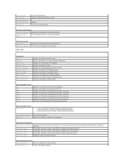
...SATA DVD+/-RW Super Multi Drive or Blu‑ray Disc™ combo or Blu‑ray Disc RW optical drive one 3.5 inch bay for a FlexBay drive Internally accessible two 3.5-inch drive bays for , and upgrading your computer. INSPIRON Specifications Computer Model Inspiron 535 Inspiron 537 Inspiron 545 Inspiron... 546 This section provides information that you may vary by region. NOTE: Offerings may need when setting up, updating drivers for SATA hard drives 50
...SATA DVD+/-RW Super Multi Drive or Blu‑ray Disc™ combo or Blu‑ray Disc RW optical drive one 3.5 inch bay for a FlexBay drive Internally accessible two 3.5-inch drive bays for , and upgrading your computer. INSPIRON Specifications Computer Model Inspiron 535 Inspiron 537 Inspiron 545 Inspiron... 546 This section provides information that you may vary by region. NOTE: Offerings may need when setting up, updating drivers for SATA hard drives 50


