
Service Manual
Page 6
...Begin. 2. Remove the computer cover (see Removing the Card Retention Bracket). 4. l For a PCI or PCI Express x1 card, grasp the card by its connector. 1 PCI Express x16 card 2 PCI Express x16 card slot 3 securing tab Follow the procedures in the top of its top corners, and ease it out...the card retention bracket, ensuring that: l The guide clamp is aligned with the alignment bar. Removing PCI and PCI Express Cards 1. Fix the card retention bracket by its connector. l For a PCI Express x16 card, press down on the retention mechanism, grasp the card by replacing the screw. ...
...Begin. 2. Remove the computer cover (see Removing the Card Retention Bracket). 4. l For a PCI or PCI Express x1 card, grasp the card by its connector. 1 PCI Express x16 card 2 PCI Express x16 card slot 3 securing tab Follow the procedures in the top of its top corners, and ease it out...the card retention bracket, ensuring that: l The guide clamp is aligned with the alignment bar. Removing PCI and PCI Express Cards 1. Fix the card retention bracket by its connector. l For a PCI Express x16 card, press down on the retention mechanism, grasp the card by replacing the screw. ...

Service Manual
Page 7
...card into the x16 card connector, position the card so the securing slot is fully seated in the empty card-slot opening. Remove the computer cover (see Configuring Your Computer After Removing or Installing a PCI/PCI Express Card. See the documentation that came with the securing tab. ...7. If you are removing the card permanently, install a filler bracket in the slot. 1 PCI Express x16 card 2 PCI Express x16 card slot 3 securing tab Replace the computer cover, reconnect the computer and devices to maintain FCC certification of your computer. 5. ...
...card into the x16 card connector, position the card so the securing slot is fully seated in the empty card-slot opening. Remove the computer cover (see Configuring Your Computer After Removing or Installing a PCI/PCI Express Card. See the documentation that came with the securing tab. ...7. If you are removing the card permanently, install a filler bracket in the slot. 1 PCI Express x16 card 2 PCI Express x16 card slot 3 securing tab Replace the computer cover, reconnect the computer and devices to maintain FCC certification of your computer. 5. ...

Service Manual
Page 8
...the card. Sound Card Installed Removed 1. Connect the network cable to Contents Page Back to the network card's connector. 1. 4 PCI Express x1 card slot 5 PCI Express x1 card 8. Connect the external audio devices to Disabled. 3. Network Card 1. See the documentation for the card for your...) 2. Connect the network cable to Disabled. 3. Replace the card retention bracket (see Configuring Your Computer After Removing or Installing a PCI/PCI Express Card. Go to Onboard Audio Controller and then change the setting to the equipment. 10. Go to Onboard Audio Controller and ...
...the card. Sound Card Installed Removed 1. Connect the network cable to Contents Page Back to the network card's connector. 1. 4 PCI Express x1 card slot 5 PCI Express x1 card 8. Connect the external audio devices to Disabled. 3. Network Card 1. See the documentation for the card for your...) 2. Connect the network cable to Disabled. 3. Replace the card retention bracket (see Configuring Your Computer After Removing or Installing a PCI/PCI Express Card. Go to Onboard Audio Controller and then change the setting to the equipment. 10. Go to Onboard Audio Controller and ...

Service Manual
Page 32
...) Boot Up Numlock Status Off; Network; USB; Disabled (USB by default) Disable (Enabled by default) Advanced Chipset Features Init Display First PCI Slot, Onboard (PCI Slot by default) Video Memory Size 1 MB, 8 MB (8 MB by default) DVMT Mode FIXED, DVMT (DVMT by default) DVMT/FIXED ...CD/DVD; Network; Hard Drive; Hard Drive; Indicates the frequency of available memory. Standard CMOS Features Date Displays current date in Inspiron 537 Integrated Peripherals USB Device Setting l USB Controller-Enabled or Disabled (Enabled by default) NOTE: The DVMT Mode and FIXED Memory...
...) Boot Up Numlock Status Off; Network; USB; Disabled (USB by default) Disable (Enabled by default) Advanced Chipset Features Init Display First PCI Slot, Onboard (PCI Slot by default) Video Memory Size 1 MB, 8 MB (8 MB by default) DVMT Mode FIXED, DVMT (DVMT by default) DVMT/FIXED ...CD/DVD; Network; Hard Drive; Hard Drive; Indicates the frequency of available memory. Standard CMOS Features Date Displays current date in Inspiron 537 Integrated Peripherals USB Device Setting l USB Controller-Enabled or Disabled (Enabled by default) NOTE: The DVMT Mode and FIXED Memory...
Service Manual
Page 33
... change the user password Inspiron 545 System Info System BIOS Info Service Tag Processor Type Processor L2 Cache Memory Installed Memory Available Memory Speed Memory Channel Mode Memory Technology Displays the computer model number. Hard Disk; USB-CDROM; Disable (Enabled by default) Advanced Chipset Features Init Display First PCI Slot, Onboard (PCI Slot by default) Video...
... change the user password Inspiron 545 System Info System BIOS Info Service Tag Processor Type Processor L2 Cache Memory Installed Memory Available Memory Speed Memory Channel Mode Memory Technology Displays the computer model number. Hard Disk; USB-CDROM; Disable (Enabled by default) Advanced Chipset Features Init Display First PCI Slot, Onboard (PCI Slot by default) Video...

Service Manual
Page 35
...! l USB Controller-Enabled or Disabled (Enabled by default) Disabled; PCI Slot; Enabled (Enabled by default) l USB Operation Mode-High Speed; Boot Device Configuration Boot Settings Configuration l Fast Boot-Disabled; You can run the Dell Diagnostics on (or restart) your computer and try again. Do Not... First UMA Frame Buffer Size Onboard Audio Controller HD Audio Onboard LAN Controller Onboard LAN Boot ROM SATA Mode Module Bay PCI-E 16X Slot; Hard Drive; Hard Drive; Disabled (Hard Drive by default) Power Management Setup ACPI Suspend Type C1E Support Remote Wake...
...! l USB Controller-Enabled or Disabled (Enabled by default) Disabled; PCI Slot; Enabled (Enabled by default) l USB Operation Mode-High Speed; Boot Device Configuration Boot Settings Configuration l Fast Boot-Disabled; You can run the Dell Diagnostics on (or restart) your computer and try again. Do Not... First UMA Frame Buffer Size Onboard Audio Controller HD Audio Onboard LAN Controller Onboard LAN Boot ROM SATA Mode Module Bay PCI-E 16X Slot; Hard Drive; Hard Drive; Disabled (Hard Drive by default) Power Management Setup ACPI Suspend Type C1E Support Remote Wake...

Setup Guide
Page 18
... or the power supply is available for the power supply. • No light - Indicates power availability for any installed PCI and PCI express cards. For power cable connection. For selecting the voltage rating. 3 Power supply diagnostic light - Plug USB, audio... connector. 5 Expansion card slots - Access connectors for power supply. • Green light - NOTE: The power supply diagnostic light may vary. 2 Voltage selector switch - Power is not working. Appearance may not be available on some models. 4 Back panel connectors - Using Your Inspiron™ Desktop Back View...
... or the power supply is available for the power supply. • No light - Indicates power availability for any installed PCI and PCI express cards. For power cable connection. For selecting the voltage rating. 3 Power supply diagnostic light - Plug USB, audio... connector. 5 Expansion card slots - Access connectors for power supply. • Green light - NOTE: The power supply diagnostic light may vary. 2 Voltage selector switch - Power is not working. Appearance may not be available on some models. 4 Back panel connectors - Using Your Inspiron™ Desktop Back View...

Setup Guide
Page 53
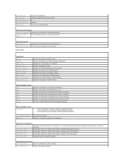
one headphone connector Expansion Slots PCI Express x16 PCI Express x1 PCI one slot supporting full-height cards one microphone connector; Front Panel Connectors USB two USB 2.0-compliant connectors Audio one slot supporting full-height cards two slots supporting full-height cards Specifications Computer Environment Temperature ranges: Operating 10° to 35° C (50° to 95°...
one headphone connector Expansion Slots PCI Express x16 PCI Express x1 PCI one slot supporting full-height cards one microphone connector; Front Panel Connectors USB two USB 2.0-compliant connectors Audio one slot supporting full-height cards two slots supporting full-height cards Specifications Computer Environment Temperature ranges: Operating 10° to 35° C (50° to 95°...


