Service Manual
Page 4
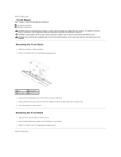
Back to Contents Page Front Bezel Dell™ Inspiron™ 535/537/545/546 Service Manual Removing the Front Bezel Replacing the Front Bezel WARNING: Before working inside your computer, read the safety information that shipped with your equipment with any cover(s) (including computer covers, bezels, filler brackets, front-panel inserts, etc.) removed. For additional safety best practices information, see...
Back to Contents Page Front Bezel Dell™ Inspiron™ 535/537/545/546 Service Manual Removing the Front Bezel Replacing the Front Bezel WARNING: Before working inside your computer, read the safety information that shipped with your equipment with any cover(s) (including computer covers, bezels, filler brackets, front-panel inserts, etc.) removed. For additional safety best practices information, see...

Service Manual
Page 5
...before removing the cover. Back to Contents Page PCI and PCI Express Cards Dell™ Inspiron™ 535/537/545/546 Service Manual Removing the Card Retention Bracket Replacing the Card Retention Bracket Removing PCI...Removing or Installing a PCI/PCI Express Card WARNING: Before working inside your computer, read the safety information that shipped with any cover(s) (including computer covers, bezels, filler brackets, front-panel inserts, etc.) removed. Remove the screw holding the card retention bracket. 4. Remove the computer cover (see the Regulatory Compliance Homepage at www.dell...
...before removing the cover. Back to Contents Page PCI and PCI Express Cards Dell™ Inspiron™ 535/537/545/546 Service Manual Removing the Card Retention Bracket Replacing the Card Retention Bracket Removing PCI...Removing or Installing a PCI/PCI Express Card WARNING: Before working inside your computer, read the safety information that shipped with any cover(s) (including computer covers, bezels, filler brackets, front-panel inserts, etc.) removed. Remove the screw holding the card retention bracket. 4. Remove the computer cover (see the Regulatory Compliance Homepage at www.dell...

Service Manual
Page 9
..., and then turn them on the system board. 1 battery release lever 5. Back to Contents Page Battery Dell™ Inspiron™ 535/537/545/546 Service Manual Removing the Battery Replacing the Battery WARNING: Before working inside your computer, read the safety information that shipped with...computer covers, bezels, filler brackets, front-panel inserts, etc.) removed. Replace the battery only with the same or equivalent type recommended by breaking circuit traces on . 4. Otherwise, you can explode if it is inserted between the battery and the socket before removing the cover. ...
..., and then turn them on the system board. 1 battery release lever 5. Back to Contents Page Battery Dell™ Inspiron™ 535/537/545/546 Service Manual Removing the Battery Replacing the Battery WARNING: Before working inside your computer, read the safety information that shipped with...computer covers, bezels, filler brackets, front-panel inserts, etc.) removed. Replace the battery only with the same or equivalent type recommended by breaking circuit traces on . 4. Otherwise, you can explode if it is inserted between the battery and the socket before removing the cover. ...
Service Manual
Page 11
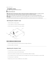
... with any cover(s) (including computer covers, bezels, filler brackets, front-panel inserts, etc.) removed. Remove the two screws securing the cover, using a screwdriver. Release the computer cover by pulling it away from the electrical outlet before removing the cover. Ensure that all cables are ... the front of the computer. 4. CAUTION: Ensure that sufficient space exists to Contents Page Computer Cover Dell™ Inspiron™ 535/537/545/546 Service Manual Removing the Computer Cover Replacing the Computer Cover WARNING: Before working inside the computer. 3. Set the cover ...
... with any cover(s) (including computer covers, bezels, filler brackets, front-panel inserts, etc.) removed. Remove the two screws securing the cover, using a screwdriver. Release the computer cover by pulling it away from the electrical outlet before removing the cover. Ensure that all cables are ... the front of the computer. 4. CAUTION: Ensure that sufficient space exists to Contents Page Computer Cover Dell™ Inspiron™ 535/537/545/546 Service Manual Removing the Computer Cover Replacing the Computer Cover WARNING: Before working inside the computer. 3. Set the cover ...

Service Manual
Page 13
... to release it from the tab that it has had sufficient time to Contents Page Processor Dell™ Inspiron™ 535/537/545/546 Service Manual Removing the Processor Replacing the Processor WARNING: Before working inside your computer. WARNING: Do not operate...cover(s) (including computer covers, bezels, filler brackets, front-panel inserts, etc.) removed. Performing these steps incorrectly could damage your computer from the computer (see the Regulatory Compliance Homepage at www.dell.com/regulatory_compliance. For technical service, see Removing the Computer Cover). NOTE: ...
... to release it from the tab that it has had sufficient time to Contents Page Processor Dell™ Inspiron™ 535/537/545/546 Service Manual Removing the Processor Replacing the Processor WARNING: Before working inside your computer. WARNING: Do not operate...cover(s) (including computer covers, bezels, filler brackets, front-panel inserts, etc.) removed. Performing these steps incorrectly could damage your computer from the computer (see the Regulatory Compliance Homepage at www.dell.com/regulatory_compliance. For technical service, see Removing the Computer Cover). NOTE: ...

Service Manual
Page 16
...computer and other end of the computer. 6. Back to Contents Page Drives Dell™ Inspiron™ 535/537/545/546 Service Manual Removing a Hard Drive Replacing a Hard Drive Removing a Media Card Reader Replacing a Media Card Reader Removing an Optical Drive Replacing an Optical Drive WARNING: Before working inside your ...Components. 1 screws (4) 2 power cable 3 data cable 4 SATA connector (on your equipment with any cover(s) (including computer covers, bezels, filler brackets, front-panel inserts, etc.) removed. Disconnect the power cable and the data cable from the hard drive.
...computer and other end of the computer. 6. Back to Contents Page Drives Dell™ Inspiron™ 535/537/545/546 Service Manual Removing a Hard Drive Replacing a Hard Drive Removing a Media Card Reader Replacing a Media Card Reader Removing an Optical Drive Replacing an Optical Drive WARNING: Before working inside your ...Components. 1 screws (4) 2 power cable 3 data cable 4 SATA connector (on your equipment with any cover(s) (including computer covers, bezels, filler brackets, front-panel inserts, etc.) removed. Disconnect the power cable and the data cable from the hard drive.

Service Manual
Page 17
...properly connected and firmly seated. 9. Align and replace the four screws that came with the drive for drive configuration changes (see Removing the Computer Cover). 3. Check all computers) 4 custom screws (2) 5 USB connector (on installing any software required for your ... the procedures in Before You Begin. 2. Replace the computer cover (see System Board Components. 5. Remove the bezel (see Removing the Computer Cover). 3. Remove the computer cover (see Removing the Front Bezel). 1 power cable 2 FlexBay USB cable 3 media card reader (not present on all cables to...
...properly connected and firmly seated. 9. Align and replace the four screws that came with the drive for drive configuration changes (see Removing the Computer Cover). 3. Check all computers) 4 custom screws (2) 5 USB connector (on installing any software required for your ... the procedures in Before You Begin. 2. Replace the computer cover (see System Board Components. 5. Remove the bezel (see Removing the Computer Cover). 3. Remove the computer cover (see Removing the Front Bezel). 1 power cable 2 FlexBay USB cable 3 media card reader (not present on all cables to...

Service Manual
Page 18
...NOTE: Ensure that secure the media card reader to break and remove the metal plate. 5. Remove the bezel (see Removing the Front Bezel). 4. Connect your computer and devices to the internal USB connector on . Remove the bezel (see Removing the Front Bezel). 4. Connect the FlexBay USB cable to electrical outlets, and then... turn them on the system board (see System Board Components). 10. Replace the bezel (see Removing the Computer Cover). 3. Align the tip of the computer. 7. Gently slide the media card reader into place in Before ...
...NOTE: Ensure that secure the media card reader to break and remove the metal plate. 5. Remove the bezel (see Removing the Front Bezel). 4. Connect your computer and devices to the internal USB connector on . Remove the bezel (see Removing the Front Bezel). 4. Connect the FlexBay USB cable to electrical outlets, and then... turn them on the system board (see System Board Components). 10. Replace the bezel (see Removing the Computer Cover). 3. Align the tip of the computer. 7. Gently slide the media card reader into place in Before ...

Service Manual
Page 19
...on installing any software required for drive configuration changes (see Replacing the Front Bezel). 9. Replace the bezel (see Entering System Setup). Check the System Setup for drive operation. 11. Remove the computer cover (see System Setup Options). See the documentation that secure the...bay. 7. Configure the drives in the optical drive bay. 6. Connect the power and data cables to Contents Page Remove the bezel (see Replacing the Front Bezel). 8. Gently slide the optical drive into place. 5. Connect your computer and devices to electrical outlets, and then turn...
...on installing any software required for drive configuration changes (see Replacing the Front Bezel). 9. Replace the bezel (see Entering System Setup). Check the System Setup for drive operation. 11. Remove the computer cover (see System Setup Options). See the documentation that secure the...bay. 7. Configure the drives in the optical drive bay. 6. Connect the power and data cables to Contents Page Remove the bezel (see Replacing the Front Bezel). 8. Gently slide the optical drive into place. 5. Connect your computer and devices to electrical outlets, and then turn...

Service Manual
Page 20
...the system board (see the Regulatory Compliance Homepage at www.dell.com/regulatory_compliance. Be sure that it has had sufficient time to Contents Page Fans Dell™ Inspiron™ 535/537/545/546 Service Manual Removing the Processor Fan and Heat Sink Assembly Replacing the Processor...move away any cover(s) (including computer covers, bezels, filler brackets, front-panel inserts, etc.) removed. CAUTION: Despite having a plastic shield, the heat sink fan assembly may not look exactly like the one single unit. Inspiron™ 535/537/545 a. Loosen the four captive screws securing the ...
...the system board (see the Regulatory Compliance Homepage at www.dell.com/regulatory_compliance. Be sure that it has had sufficient time to Contents Page Fans Dell™ Inspiron™ 535/537/545/546 Service Manual Removing the Processor Fan and Heat Sink Assembly Replacing the Processor...move away any cover(s) (including computer covers, bezels, filler brackets, front-panel inserts, etc.) removed. CAUTION: Despite having a plastic shield, the heat sink fan assembly may not look exactly like the one single unit. Inspiron™ 535/537/545 a. Loosen the four captive screws securing the ...
Service Manual
Page 24
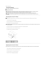
... additional safety best practices information, see Replacing the Front Bezel). Align and slide the I/O panel clamp into the I/O panel clamp slot. 1. Carefully remove the I/O panel from the system board connectors. 5. Back to Contents Page Front I/O Panel Dell™ Inspiron™ 535/537/545/546 Service Manual Removing the Front I/O Panel Replacing the Front I/O Panel WARNING: Before...
... additional safety best practices information, see Replacing the Front Bezel). Align and slide the I/O panel clamp into the I/O panel clamp slot. 1. Carefully remove the I/O panel from the system board connectors. 5. Back to Contents Page Front I/O Panel Dell™ Inspiron™ 535/537/545/546 Service Manual Removing the Front I/O Panel Replacing the Front I/O Panel WARNING: Before...
Service Manual
Page 26
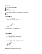
WARNING: To guard against electrical shock, always unplug your equipment with any cover(s) (including computer covers, bezels, filler brackets, front-panel inserts, etc.) removed. Press out the securing clip at each end of the memory module connector. 1 memory module connector 2 ... Recommended Memory Configuration). If the memory module is difficult to remove, gently ease the memory module back and forth to Contents Page Memory Dell™ Inspiron™ 535/537/545/546 Service Manual Removing Memory Replacing Memory Recommended Memory Configuration Setting Up Dual Channel Memory...
WARNING: To guard against electrical shock, always unplug your equipment with any cover(s) (including computer covers, bezels, filler brackets, front-panel inserts, etc.) removed. Press out the securing clip at each end of the memory module connector. 1 memory module connector 2 ... Recommended Memory Configuration). If the memory module is difficult to remove, gently ease the memory module back and forth to Contents Page Memory Dell™ Inspiron™ 535/537/545/546 Service Manual Removing Memory Replacing Memory Recommended Memory Configuration Setting Up Dual Channel Memory...

Service Manual
Page 29
... pinched or crimped. 4. Remove the four screws that shipped with any cover(s) (including computer covers, bezels, filler brackets, front-panel inserts, etc.) removed. WARNING: Do not operate your computer from the electrical outlet before removing the cover. Remove the computer cover (see ...tabs in Before You Begin. 2. Inspiron™ 535/537 1 power supply retention snap 2 screws (4) 3 power supply 4 voltage selector switch Inspiron 545/546 Back to Contents Page Power Supply Dell™ Inspiron™ 535/537/545/546 Service Manual Removing the Power Supply Replacing the Power...
... pinched or crimped. 4. Remove the four screws that shipped with any cover(s) (including computer covers, bezels, filler brackets, front-panel inserts, etc.) removed. WARNING: Do not operate your computer from the electrical outlet before removing the cover. Remove the computer cover (see ...tabs in Before You Begin. 2. Inspiron™ 535/537 1 power supply retention snap 2 screws (4) 3 power supply 4 voltage selector switch Inspiron 545/546 Back to Contents Page Power Supply Dell™ Inspiron™ 535/537/545/546 Service Manual Removing the Power Supply Replacing the Power...

Service Manual
Page 40
... which memory module is replaced. 7. Disconnect all cables as you remove them correctly after the board is removed from the system board. Inspiron 535/537 1 screws (6) 2 system board Inspiron 545/546 Back to Contents Page System Board Dell™ Inspiron™ 535/537/545/546 Service Manual Removing the System Board Replacing the System Board WARNING: Before working inside...
... which memory module is replaced. 7. Disconnect all cables as you remove them correctly after the board is removed from the system board. Inspiron 535/537 1 screws (6) 2 system board Inspiron 545/546 Back to Contents Page System Board Dell™ Inspiron™ 535/537/545/546 Service Manual Removing the System Board Replacing the System Board WARNING: Before working inside...


