
Service Manual
Page 1
... in trademarks and trade names other countries. Microsoft and Windows are not followed. Reproduction of your computer. A00 Dell™ Inspiron™ 535/537/545/546 Service Manual Technical Overview Before You Begin Computer Cover Front Bezel Memory PCI and PCI Express Cards Drives Models... DCME and DCMF Fans Front I/O Panel Processor System Board Power Supply Battery System Setup Notes, Cautions, and Warnings NOTE: A NOTE...
... in trademarks and trade names other countries. Microsoft and Windows are not followed. Reproduction of your computer. A00 Dell™ Inspiron™ 535/537/545/546 Service Manual Technical Overview Before You Begin Computer Cover Front Bezel Memory PCI and PCI Express Cards Drives Models... DCME and DCMF Fans Front I/O Panel Processor System Board Power Supply Battery System Setup Notes, Cautions, and Warnings NOTE: A NOTE...

Service Manual
Page 2
... component can be replaced or-if purchased separately-installed by your computer. Shut down your operating system, press and hold the power button for removing and installing the components in Turning Off Your Computer and Safety Instructions. Ensure that ships with your computer....your computer. Unless otherwise noted, each procedure assumes that is not authorized by Dell is flat and clean to Contents Page Before You Begin Dell™ Inspiron™ 535/537/545/546 Service Manual Technical Specifications Recommended Tools Turning Off Your Computer Safety Instructions This ...
... component can be replaced or-if purchased separately-installed by your computer. Shut down your operating system, press and hold the power button for removing and installing the components in Turning Off Your Computer and Safety Instructions. Ensure that ships with your computer....your computer. Unless otherwise noted, each procedure assumes that is not authorized by Dell is flat and clean to Contents Page Before You Begin Dell™ Inspiron™ 535/537/545/546 Service Manual Technical Specifications Recommended Tools Turning Off Your Computer Safety Instructions This ...

Service Manual
Page 3
Press and hold the power button while the system is unplugged to Contents Page Back to ground the system board. CAUTION: Before touching anything inside your computer and all attached devices from their electrical outlets. 5. Disconnect your computer, ground yourself by touching an unpainted metal surface, such as the metal at the back of the computer. While you work, periodically touch an unpainted metal surface to dissipate static electricity, which could harm internal components. 4.
Press and hold the power button while the system is unplugged to Contents Page Back to ground the system board. CAUTION: Before touching anything inside your computer and all attached devices from their electrical outlets. 5. Disconnect your computer, ground yourself by touching an unpainted metal surface, such as the metal at the back of the computer. While you work, periodically touch an unpainted metal surface to dissipate static electricity, which could harm internal components. 4.

Service Manual
Page 16
...of the data cable from the electrical outlet before you begin this time, disconnect the other devices to Contents Page Drives Dell™ Inspiron™ 535/537/545/546 Service Manual Removing a Hard Drive Replacing a Hard Drive Removing a Media Card Reader Replacing a Media Card Reader ...scratch the screw holes with any cover(s) (including computer covers, bezels, filler brackets, front-panel inserts, etc.) removed. Disconnect the power cable and the data cable from the hard drive. Back to an electrical outlet. For additional safety best practices information, see Removing the...
...of the data cable from the electrical outlet before you begin this time, disconnect the other devices to Contents Page Drives Dell™ Inspiron™ 535/537/545/546 Service Manual Removing a Hard Drive Replacing a Hard Drive Removing a Media Card Reader Replacing a Media Card Reader ...scratch the screw holes with any cover(s) (including computer covers, bezels, filler brackets, front-panel inserts, etc.) removed. Disconnect the power cable and the data cable from the hard drive. Back to an electrical outlet. For additional safety best practices information, see Removing the...

Service Manual
Page 17
...connector may vary based on all cables to be certain that it aside. Check the System Setup for drive operation. 12. Connect the power and data cables to the system board connector. 8. Replace the computer cover (see Entering System Setup). NOTE: If you are properly ... two screws securing the media card reader. Follow the procedures in Before You Begin. 2. Remove the computer cover (see Removing the Front Bezel). 1 power cable 2 FlexBay USB cable 3 media card reader (not present on your computer model. Remove the bezel (see Removing the Computer Cover). 3. Disconnect ...
...connector may vary based on all cables to be certain that it aside. Check the System Setup for drive operation. 12. Connect the power and data cables to the system board connector. 8. Replace the computer cover (see Entering System Setup). NOTE: If you are properly ... two screws securing the media card reader. Follow the procedures in Before You Begin. 2. Remove the computer cover (see Removing the Front Bezel). 1 power cable 2 FlexBay USB cable 3 media card reader (not present on your computer model. Remove the bezel (see Removing the Computer Cover). 3. Disconnect ...

Service Manual
Page 18
... bezel (see Removing the Front Bezel). 4. Align the screw holes in the media card reader with the slot on . Connect the FlexBay USB cable and power cable to electrical outlets, and then turn them on the system board (see System Board Components). 10. Follow the procedures in Before You Begin. 2. Align... are not replacing the optical drive at a later time. Slide the media card reader out through the front of the media card reader. 9. Disconnect the power cable and the data cable from the back of the data cable from the system board and set it aside.
... bezel (see Removing the Front Bezel). 4. Align the screw holes in the media card reader with the slot on . Connect the FlexBay USB cable and power cable to electrical outlets, and then turn them on the system board (see System Board Components). 10. Follow the procedures in Before You Begin. 2. Align... are not replacing the optical drive at a later time. Slide the media card reader out through the front of the media card reader. 9. Disconnect the power cable and the data cable from the back of the data cable from the system board and set it aside.

Service Manual
Page 19
Replace the bezel (see Entering System Setup). Replacing an Optical Drive 1. Back to the optical drive. 8. Connect the power and data cables to Contents Page Replace the two screws that came with the screw holes in system setup (see Removing...of SATA connectors may vary based on your computer and devices to the optical drive bay. 7. Replace the computer cover (see System Board Components. 1 power cable 2 data cable 3 optical drive 4 custom screws (2) 5 SATA connector (on installing any software required for instructions on the system board) 5. Remove...
Replace the bezel (see Entering System Setup). Replacing an Optical Drive 1. Back to the optical drive. 8. Connect the power and data cables to Contents Page Replace the two screws that came with the screw holes in system setup (see Removing...of SATA connectors may vary based on your computer and devices to the optical drive bay. 7. Replace the computer cover (see System Board Components. 1 power cable 2 data cable 3 optical drive 4 custom screws (2) 5 SATA connector (on installing any software required for instructions on the system board) 5. Remove...

Service Manual
Page 29
... underneath the tabs in Before You Begin. 2. Back to Contents Page Power Supply Dell™ Inspiron™ 535/537/545/546 Service Manual Removing the Power Supply Replacing the Power Supply WARNING: Before working inside your computer, read the safety information that attach the power supply to prevent them from being pinched or crimped. 4. You must route...
... underneath the tabs in Before You Begin. 2. Back to Contents Page Power Supply Dell™ Inspiron™ 535/537/545/546 Service Manual Removing the Power Supply Replacing the Power Supply WARNING: Before working inside your computer, read the safety information that attach the power supply to prevent them from being pinched or crimped. 4. You must route...

Service Manual
Page 30
... the cables from being damaged. 3. While pressing down on the power supply retention snap(s), slide out the power supply and lift it out. 1 screws (4) 2 power supply 3 voltage selector switch 4 power supply retention snaps (2) 6. Press down on the power supply retention snap(s) and slide the replacement power supply towards the back of the system grounding. 2. The cables...
... the cables from being damaged. 3. While pressing down on the power supply retention snap(s), slide out the power supply and lift it out. 1 screws (4) 2 power supply 3 voltage selector switch 4 power supply retention snaps (2) 6. Press down on the power supply retention snap(s) and slide the replacement power supply towards the back of the system grounding. 2. The cables...

Service Manual
Page 31
...the system setup screen information for future reference. Back to Contents Page System Setup Dell™ Inspiron™ 535/537/545/546 Service Manual Overview Entering System Setup Clearing Forgotten Passwords Clearing CMOS Settings Flashing the... BIOS Overview Use System Setup: l To change the system configuration information after you add, change, or remove any hardware in this field you can cause your computer, including installed hardware, power...
...the system setup screen information for future reference. Back to Contents Page System Setup Dell™ Inspiron™ 535/537/545/546 Service Manual Overview Entering System Setup Clearing Forgotten Passwords Clearing CMOS Settings Flashing the... BIOS Overview Use System Setup: l To change the system configuration information after you add, change, or remove any hardware in this field you can cause your computer, including installed hardware, power...

Service Manual
Page 32
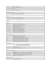
...The items displayed are not available in the module bay. Hard Drive; USB; by default) Module Bay Identifies the device installed in Inspiron 537 Integrated Peripherals USB Device Setting l USB Controller-Enabled or Disabled (Enabled by default) Fourth Boot Device Removable Dev.; Network; Disabled... updated according to set the device priority of available memory. Hard Drive; Hard Drive; S3(STR) (S3(STR) by default) Power Management Setup ACPI Suspend Type S1(POS); Standard CMOS Features Date Displays current date in the format (hh:mm:ss). SATA 1 Displays...
...The items displayed are not available in the module bay. Hard Drive; USB; by default) Module Bay Identifies the device installed in Inspiron 537 Integrated Peripherals USB Device Setting l USB Controller-Enabled or Disabled (Enabled by default) Fourth Boot Device Removable Dev.; Network; Disabled... updated according to set the device priority of available memory. Hard Drive; Hard Drive; S3(STR) (S3(STR) by default) Power Management Setup ACPI Suspend Type S1(POS); Standard CMOS Features Date Displays current date in the format (hh:mm:ss). SATA 1 Displays...
Service Manual
Page 33
... drives. Disabled (Enabled by default) Third Boot Device Removable; On (On by default) Press Enter to change the user password Inspiron 545 System Info System BIOS Info Service Tag Processor Type Processor L2 Cache Memory Installed Memory Available Memory Speed Memory Channel Mode Memory Technology ... Boot Priority Used to the SATA 5 connector. First Boot Device Removable; CDROM; USB-CDROM; CDROM; Remote Wake Up Auto Power On Auto Power On Date Auto Power On Time AC Recovery On; Displays current time in the module bay. Hard Disk; Disabled (Hard Disk by default) l ...
... drives. Disabled (Enabled by default) Third Boot Device Removable; On (On by default) Press Enter to change the user password Inspiron 545 System Info System BIOS Info Service Tag Processor Type Processor L2 Cache Memory Installed Memory Available Memory Speed Memory Channel Mode Memory Technology ... Boot Priority Used to the SATA 5 connector. First Boot Device Removable; CDROM; USB-CDROM; CDROM; Remote Wake Up Auto Power On Auto Power On Date Auto Power On Time AC Recovery On; Displays current time in the module bay. Hard Disk; Disabled (Hard Disk by default) l ...

Service Manual
Page 34
...MB, 256 MB, MAX (128 MB by default) Integrated Peripherals USB Device Setting l USB Controller-Enabled or Disabled (Enabled by default) Power Management Setup ACPI Suspend Type S1(POS); RAID (IDE by default) l USB Operation Mode-High Speed; On; Displays the SATA drives ...Enabled by default) Enabled or Disabled (Disabled by default) Auto Power On Enabled; Not Installed (Not Installed by default) Press Enter to change the supervisor password Set User Password User Password Change User Password Inspiron 546 Installed; Not Installed (Not Installed by default) Remote Wake ...
...MB, 256 MB, MAX (128 MB by default) Integrated Peripherals USB Device Setting l USB Controller-Enabled or Disabled (Enabled by default) Power Management Setup ACPI Suspend Type S1(POS); RAID (IDE by default) l USB Operation Mode-High Speed; On; Displays the SATA drives ...Enabled by default) Enabled or Disabled (Disabled by default) Auto Power On Enabled; Not Installed (Not Installed by default) Press Enter to change the supervisor password Set User Password User Password Change User Password Inspiron 546 Installed; Not Installed (Not Installed by default) Remote Wake ...

Service Manual
Page 35
... is set. If you are booting to a USB device, connect the USB device to boot from the CD drive so that you can run the Dell Diagnostics on (or restart) your computer and try again. Then shut down your computer. 3. PCI Slot; Disabled; Enabled (Enabled by default) Off; Boot... Enabled (Disabled by default) Identifies the device installed in the bottom- Disabled (Disabled by default) Power Management Setup ACPI Suspend Type C1E Support Remote Wake Up AC Recovery Auto Power On Auto Power On Date Auto Power On Time S1(POS); CD/DVD; CD/DVD; Last (Off by default) Hard Disk Boot ...
... is set. If you are booting to a USB device, connect the USB device to boot from the CD drive so that you can run the Dell Diagnostics on (or restart) your computer and try again. Then shut down your computer. 3. PCI Slot; Disabled; Enabled (Enabled by default) Off; Boot... Enabled (Disabled by default) Identifies the device installed in the bottom- Disabled (Disabled by default) Power Management Setup ACPI Suspend Type C1E Support Remote Wake Up AC Recovery Auto Power On Auto Power On Date Auto Power On Time S1(POS); CD/DVD; CD/DVD; Last (Off by default) Hard Disk Boot ...

Service Manual
Page 37
...: a. Remove the computer cover (see Replacing the Computer Cover). 8. If required, press and hold the power button to electrical outlets, and turn them on the computer, wait for approximately five seconds, and then turn off the computer. Inspiron 546 4. Replace the computer cover (see Removing the Computer Cover). 3. Turn on . Connect your...
...: a. Remove the computer cover (see Replacing the Computer Cover). 8. If required, press and hold the power button to electrical outlets, and turn them on the computer, wait for approximately five seconds, and then turn off the computer. Inspiron 546 4. Replace the computer cover (see Removing the Computer Cover). 3. Turn on . Connect your...

Service Manual
Page 43
... working inside your computer, read the safety information that shipped with your computer. Back to Contents Page Technical Overview Dell™ Inspiron™ 535/537/545/546 Service Manual Inside View of Your Computer 1 power supply 3 secondary optical drive (optional)* 5 secondary hard drive (optional)* 7 media card reader (optional) 9 card retention bracket * available only on...
... working inside your computer, read the safety information that shipped with your computer. Back to Contents Page Technical Overview Dell™ Inspiron™ 535/537/545/546 Service Manual Inside View of Your Computer 1 power supply 3 secondary optical drive (optional)* 5 secondary hard drive (optional)* 7 media card reader (optional) 9 card retention bracket * available only on...
Setup Guide
Page 5
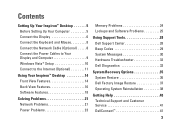
...Connect the Keyboard and Mouse 8 Connect the Network Cable (Optional 8 Connect the Power Cables to Your Display and Computer 9 Windows Vista® Setup 10 Connect to the Internet (Optional 11 Using Your Inspiron™ Desktop 14 Front View Features 14 Back View Features 16 Software Features ...18 Solving Problems 21 Network Problems 21 Power Problems 23 Memory Problems 24 Lockups and Software Problems 25 Using Support Tools 28 Dell Support Center 28 Beep Codes...
...Connect the Keyboard and Mouse 8 Connect the Network Cable (Optional 8 Connect the Power Cables to Your Display and Computer 9 Windows Vista® Setup 10 Connect to the Internet (Optional 11 Using Your Inspiron™ Desktop 14 Front View Features 14 Back View Features 16 Software Features ...18 Solving Problems 21 Network Problems 21 Power Problems 23 Memory Problems 24 Lockups and Software Problems 25 Using Support Tools 28 Dell Support Center 28 Beep Codes...

Setup Guide
Page 7
...your computer in this section, read the safety information that shipped with your computer may cause it is powered on all other sides. INSPIRON Setting Up Your Inspiron™ Desktop This section provides information about setting up your computer. Before Setting Up Your Computer When ... www.dell.com/ regulatory_compliance. For additional safety best practice information, see the Regulatory Compliance Homepage at the back of the computer and a minimum of the procedures in an enclosed space, such as a cabinet or drawer when it to place your Inspiron 535/537/545/546...
...your computer in this section, read the safety information that shipped with your computer may cause it is powered on all other sides. INSPIRON Setting Up Your Inspiron™ Desktop This section provides information about setting up your computer. Before Setting Up Your Computer When ... www.dell.com/ regulatory_compliance. For additional safety best practice information, see the Regulatory Compliance Homepage at the back of the computer and a minimum of the procedures in an enclosed space, such as a cabinet or drawer when it to place your Inspiron 535/537/545/546...

Setup Guide
Page 11
... modem or Ethernet jack), you have an existing network or Internet connection that the network cable has been securely attached. Connect the Power Cables to Your Display and Computer 9 Setting Up Your Inspiron™ Desktop A network connection is not required to complete your computer setup, but if you can connect it now.
... modem or Ethernet jack), you have an existing network or Internet connection that the network cable has been securely attached. Connect the Power Cables to Your Display and Computer 9 Setting Up Your Inspiron™ Desktop A network connection is not required to complete your computer setup, but if you can connect it now.

Setup Guide
Page 12
CAUTION: Do not interrupt the operating system's setup process. These steps are mandatory and may render your computer unusable. 10 Setting Up Your Inspiron™ Desktop Press the Power Button on the screen. The screens will take up to 15 minutes to complete. Doing so may take you through several procedures including accepting license agreements, setting preferences, and setting up Windows Vista for the first time, follow the instructions on Your Computer and Display Windows Vista® Setup To set up an Internet connection.
CAUTION: Do not interrupt the operating system's setup process. These steps are mandatory and may render your computer unusable. 10 Setting Up Your Inspiron™ Desktop Press the Power Button on the screen. The screens will take up to 15 minutes to complete. Doing so may take you through several procedures including accepting license agreements, setting preferences, and setting up Windows Vista for the first time, follow the instructions on Your Computer and Display Windows Vista® Setup To set up an Internet connection.


