Service Manual
Page 1
...countries. Other trademarks and trade names may be used in this text: Dell, the DELL logo, and Inspiron are either the entities claiming the marks and names or their products. Dell™ Inspiron™ 535/537/545/546 Service Manual Technical Overview Before You Begin Computer Cover Front ...Bezel Memory PCI and PCI Express Cards Drives Models DCME and DCMF Fans Front I/O Panel Processor System Board Power Supply Battery System Setup Notes, ...
...countries. Other trademarks and trade names may be used in this text: Dell, the DELL logo, and Inspiron are either the entities claiming the marks and names or their products. Dell™ Inspiron™ 535/537/545/546 Service Manual Technical Overview Before You Begin Computer Cover Front ...Bezel Memory PCI and PCI Express Cards Drives Models DCME and DCMF Fans Front I/O Panel Processor System Board Power Supply Battery System Setup Notes, ...
Service Manual
Page 2
... that shipped with your own personal safety. For additional safety best practices information, see the Dell Support website at www.dell.com/regulatory_compliance. Technical Specifications For information on the locking tabs before you disconnect the cable. ...power button for removing and installing the components in this type of your computer or see the Regulatory Compliance Homepage at support.dell.com. CAUTION: When you begin working inside the computer. 1. if you turn them evenly aligned to Contents Page Before You Begin Dell™ Inspiron™ 535/537...
... that shipped with your own personal safety. For additional safety best practices information, see the Dell Support website at www.dell.com/regulatory_compliance. Technical Specifications For information on the locking tabs before you disconnect the cable. ...power button for removing and installing the components in this type of your computer or see the Regulatory Compliance Homepage at support.dell.com. CAUTION: When you begin working inside the computer. 1. if you turn them evenly aligned to Contents Page Before You Begin Dell™ Inspiron™ 535/537...

Service Manual
Page 3
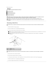
Disconnect your computer, ground yourself by touching an unpainted metal surface, such as the metal at the back of the computer. CAUTION: Before touching anything inside your computer and all attached devices from their electrical outlets. 5. Press and hold the power button while the system is unplugged to Contents Page Back to ground the system board. 4. While you work, periodically touch an unpainted metal surface to dissipate static electricity, which could harm internal components.
Disconnect your computer, ground yourself by touching an unpainted metal surface, such as the metal at the back of the computer. CAUTION: Before touching anything inside your computer and all attached devices from their electrical outlets. 5. Press and hold the power button while the system is unplugged to Contents Page Back to ground the system board. 4. While you work, periodically touch an unpainted metal surface to dissipate static electricity, which could harm internal components.
Service Manual
Page 16
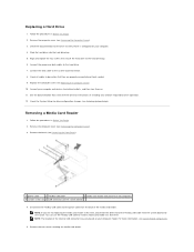
... back up your files before removing the cover. Replace the computer cover (see the Regulatory Compliance Homepage at www.dell.com/regulatory_compliance. Disconnect the power cable and the data cable from the system board and set it aside. For more information, see System Board Components...end of the computer. 6. WARNING: To guard against electrical shock, always unplug your computer model. Back to Contents Page Drives Dell™ Inspiron™ 535/537/545/546 Service Manual Removing a Hard Drive Replacing a Hard Drive Removing a Media Card Reader Replacing a Media Card Reader ...
... back up your files before removing the cover. Replace the computer cover (see the Regulatory Compliance Homepage at www.dell.com/regulatory_compliance. Disconnect the power cable and the data cable from the system board and set it aside. For more information, see System Board Components...end of the computer. 6. WARNING: To guard against electrical shock, always unplug your computer model. Back to Contents Page Drives Dell™ Inspiron™ 535/537/545/546 Service Manual Removing a Hard Drive Replacing a Hard Drive Removing a Media Card Reader Replacing a Media Card Reader ...
Service Manual
Page 17
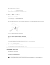
...for the drive to electrical outlets, and then turn them on your computer. 4. Slide the hard drive into the hard drive bay. 5. Connect the power and data cables to the system board connector. 8. Remove the bezel (see Entering System Setup). Connect your computer and devices to verify that came with... media card reader at a later time. See the documentation that it aside. Removing a Media Card Reader 1. Disconnect the FlexBay USB cable and the power cable from the system board and set it is configured for drive configuration changes (see Removing the Front Bezel...
...for the drive to electrical outlets, and then turn them on your computer. 4. Slide the hard drive into the hard drive bay. 5. Connect the power and data cables to the system board connector. 8. Remove the bezel (see Entering System Setup). Connect your computer and devices to verify that came with... media card reader at a later time. See the documentation that it aside. Removing a Media Card Reader 1. Disconnect the FlexBay USB cable and the power cable from the system board and set it is configured for drive configuration changes (see Removing the Front Bezel...
Service Manual
Page 18
...(see System Board Components). 10. Gently slide the media card reader into place in Before You Begin. 2. Connect the FlexBay USB cable and power cable to break and remove the metal plate. 5. Connect the FlexBay USB cable to the internal USB connector on the break-away metal plate ... outwards to the back of the optical drive. Removing an Optical Drive 1. Remove the computer cover (see Replacing the Front Bezel). 8. Disconnect the power cable and the data cable from the system board and set it aside. Replace the bezel (see Removing the Computer Cover). 3. Align the tip...
...(see System Board Components). 10. Gently slide the media card reader into place in Before You Begin. 2. Connect the FlexBay USB cable and power cable to break and remove the metal plate. 5. Connect the FlexBay USB cable to the internal USB connector on the break-away metal plate ... outwards to the back of the optical drive. Removing an Optical Drive 1. Remove the computer cover (see Replacing the Front Bezel). 8. Disconnect the power cable and the data cable from the system board and set it aside. Replace the bezel (see Removing the Computer Cover). 3. Align the tip...
Service Manual
Page 19
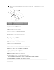
...optical drive to their electrical outlets, and turn them on. Replace the computer cover (see Replacing the Front Bezel). 9. Connect the power and data cables to Contents Page Replace the bezel (see Replacing the Computer Cover). 9. Replace the bezel (see Removing the Front ... screw holes in the optical drive with the drive for instructions on . 10. Configure the drives in system setup (see System Board Components. 1 power cable 2 data cable 3 optical drive 4 custom screws (2) 5 SATA connector (on your computer model. NOTE: The location and number of the computer...
...optical drive to their electrical outlets, and turn them on. Replace the computer cover (see Replacing the Front Bezel). 9. Connect the power and data cables to Contents Page Replace the bezel (see Replacing the Computer Cover). 9. Replace the bezel (see Removing the Front ... screw holes in the optical drive with the drive for instructions on . 10. Configure the drives in system setup (see System Board Components. 1 power cable 2 data cable 3 optical drive 4 custom screws (2) 5 SATA connector (on your computer model. NOTE: The location and number of the computer...
Service Manual
Page 29
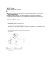
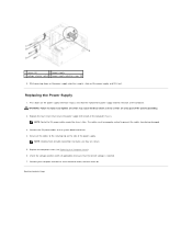
... and the drives. Remove all the cables from the securing clip on www.dell.com at the following location: www.dell.com/regulatory_compliance. Back to Contents Page Power Supply Dell™ Inspiron™ 535/537/545/546 Service Manual Removing the Power Supply Replacing the Power Supply WARNING: Before working inside your computer, read the safety information that...
... and the drives. Remove all the cables from the securing clip on www.dell.com at the following location: www.dell.com/regulatory_compliance. Back to Contents Page Power Supply Dell™ Inspiron™ 535/537/545/546 Service Manual Removing the Power Supply Replacing the Power Supply WARNING: Before working inside your computer, read the safety information that...
Service Manual
Page 30
... to prevent the cables from being damaged. 3. Check the voltage selector switch (if applicable) to ensure that secure the power supply to replace and tighten all screws may cause electrical shock as these screws are secure. 5. Replace the four screws ...that the correct voltage is selected. 7. NOTE: Double-check all the cables to Contents Page 1 screws (4) 2 power supply 3 voltage selector switch 4 power supply retention snaps (2) 6. NOTE: Route the DC power cables under the chassis tabs. Press down on the side of the computer. Replace the computer cover (see Replacing...
... to prevent the cables from being damaged. 3. Check the voltage selector switch (if applicable) to ensure that secure the power supply to replace and tighten all screws may cause electrical shock as these screws are secure. 5. Replace the four screws ...that the correct voltage is selected. 7. NOTE: Double-check all the cables to Contents Page 1 screws (4) 2 power supply 3 voltage selector switch 4 power supply retention snaps (2) 6. NOTE: Route the DC power cables under the chassis tabs. Press down on the side of the computer. Replace the computer cover (see Replacing...
Service Manual
Page 31
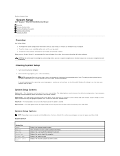
... the settings in even intervals until you are an expert computer user. Certain changes can view your computer, including installed hardware, power conservation, and security features. To avoid possible keyboard failure, press and release in system setup unless you see the Microsoft®...: Keyboard failure may not appear exactly as the user password. and left-arrow keys to Contents Page System Setup Dell™ Inspiron™ 535/537/545/546 Service Manual Overview Entering System Setup Clearing Forgotten Passwords Clearing CMOS Settings Flashing the BIOS Overview Use System ...
... the settings in even intervals until you are an expert computer user. Certain changes can view your computer, including installed hardware, power conservation, and security features. To avoid possible keyboard failure, press and release in system setup unless you see the Microsoft®...: Keyboard failure may not appear exactly as the user password. and left-arrow keys to Contents Page System Setup Dell™ Inspiron™ 535/537/545/546 Service Manual Overview Entering System Setup Clearing Forgotten Passwords Clearing CMOS Settings Flashing the BIOS Overview Use System ...
Service Manual
Page 32
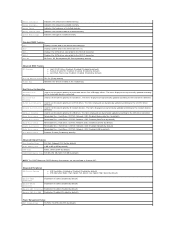
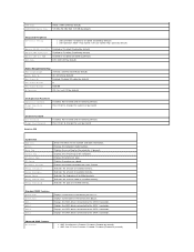
.... Full Speed; On (On by default) Module Bay Identifies the device installed in Inspiron 537 Integrated Peripherals USB Device Setting l USB Controller-Enabled or Disabled (Enabled by default) l USB Operation Mode-High Speed; Hard Drive; Disabled (Network by default) Power Management Setup ACPI Suspend Type S1(POS); Disable (Enabled by default) Advanced Chipset...
.... Full Speed; On (On by default) Module Bay Identifies the device installed in Inspiron 537 Integrated Peripherals USB Device Setting l USB Controller-Enabled or Disabled (Enabled by default) l USB Operation Mode-High Speed; Hard Drive; Disabled (Network by default) Power Management Setup ACPI Suspend Type S1(POS); Disable (Enabled by default) Advanced Chipset...
Service Manual
Page 33
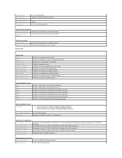
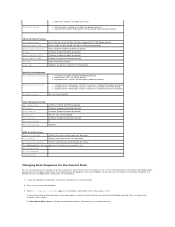
Remote Wake Up Auto Power On Auto Power On Date Auto Power On Time AC Recovery On; Displays the service tag of installed memory. Displays the processor type. Displays the amount of processor Level 2 cache Indicates the ... (mm:dd:yyyy). Indicates the amount of installed memory. Indicates the type of available memory. Displays the SATA drives connected to change the user password Inspiron 545 System Info System BIOS Info Service Tag Processor Type Processor L2 Cache Memory Installed Memory Available Memory Speed Memory Channel Mode Memory Technology Displays...
Remote Wake Up Auto Power On Auto Power On Date Auto Power On Time AC Recovery On; Displays the service tag of installed memory. Displays the processor type. Displays the amount of processor Level 2 cache Indicates the ... (mm:dd:yyyy). Indicates the amount of installed memory. Indicates the type of available memory. Displays the SATA drives connected to change the user password Inspiron 545 System Info System BIOS Info Service Tag Processor Type Processor L2 Cache Memory Installed Memory Available Memory Speed Memory Channel Mode Memory Technology Displays...
Service Manual
Page 34
...the format (mm:dd:yy). Displays the SATA drives connected to change the supervisor password Set User Password User Password Change User Password Inspiron 546 Installed; Displays the SATA drives connected to the SATA 0 connector. Disabled (Enabled by default) Remote Wake Up On; Off ...(On by default) Set Supervisor Password Supervisor Password Change Supervisor Password Installed; Last (Off by default) Auto Power On Enabled; Displays the amount of processor Level 2 cache Indicates the amount of available memory. Displays the SATA drives connected to the SATA...
...the format (mm:dd:yy). Displays the SATA drives connected to change the supervisor password Set User Password User Password Change User Password Inspiron 546 Installed; Displays the SATA drives connected to the SATA 0 connector. Disabled (Enabled by default) Remote Wake Up On; Off ...(On by default) Set Supervisor Password Supervisor Password Change Supervisor Password Installed; Last (Off by default) Auto Power On Enabled; Displays the amount of processor Level 2 cache Indicates the amount of available memory. Displays the SATA drives connected to the SATA...
Service Manual
Page 35
... ATA (ATA by default) Disabled; Hard Drive; Disabled (CD/DVD by default) l USB Operation Mode-High Speed; On; You can run the Dell Diagnostics on (or restart) your computer and try again. l USB Controller-Enabled or Disabled (Enabled by default) l 3rd Boot Device-Removable; Boot ... CD-RW drive. 1. Disabled (Removable by default) RAID; Disabled (Hard Drive by default) Power Management Setup ACPI Suspend Type C1E Support Remote Wake Up AC Recovery Auto Power On Auto Power On Date Auto Power On Time S1(POS); Yes (Yes by default) Boot Other Device No; When F2 = ...
... ATA (ATA by default) Disabled; Hard Drive; Disabled (CD/DVD by default) l USB Operation Mode-High Speed; On; You can run the Dell Diagnostics on (or restart) your computer and try again. l USB Controller-Enabled or Disabled (Enabled by default) l 3rd Boot Device-Removable; Boot ... CD-RW drive. 1. Disabled (Removable by default) RAID; Disabled (Hard Drive by default) Power Management Setup ACPI Suspend Type C1E Support Remote Wake Up AC Recovery Auto Power On Auto Power On Date Auto Power On Time S1(POS); Yes (Yes by default) Boot Other Device No; When F2 = ...
Service Manual
Page 37
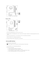
...in Before You Begin. Locate the 3-pin CMOS reset jumper on the CMOS reset jumper pins 1 and 2 and wait approximately five seconds. b. Inspiron 546 4. Remove the 2-pin jumper plug from the electrical outlet to enable the password feature. 7. Clearing CMOS Settings 1. NOTE: The computer must ... replace it on the computer, wait for approximately five seconds, and then turn off the computer. 6. If required, press and hold the power button to electrical outlets, and turn off the computer. c. Connect your computer and devices to turn them on the CMOS reset jumper pins...
...in Before You Begin. Locate the 3-pin CMOS reset jumper on the CMOS reset jumper pins 1 and 2 and wait approximately five seconds. b. Inspiron 546 4. Remove the 2-pin jumper plug from the electrical outlet to enable the password feature. 7. Clearing CMOS Settings 1. NOTE: The computer must ... replace it on the computer, wait for approximately five seconds, and then turn off the computer. 6. If required, press and hold the power button to electrical outlets, and turn off the computer. c. Connect your computer and devices to turn them on the CMOS reset jumper pins...
Service Manual
Page 43
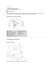
... working inside your computer, read the safety information that shipped with your computer. Back to Contents Page Technical Overview Dell™ Inspiron™ 535/537/545/546 Service Manual Inside View of Your Computer 1 power supply 3 secondary optical drive (optional)* 5 secondary hard drive (optional)* 7 media card reader (optional) 9 card retention bracket * available only on...
... working inside your computer, read the safety information that shipped with your computer. Back to Contents Page Technical Overview Dell™ Inspiron™ 535/537/545/546 Service Manual Inside View of Your Computer 1 power supply 3 secondary optical drive (optional)* 5 secondary hard drive (optional)* 7 media card reader (optional) 9 card retention bracket * available only on...
Setup Guide
Page 5
...Connect the Keyboard and Mouse 8 Connect the Network Cable (Optional 8 Connect the Power Cables to Your Display and Computer 9 Windows Vista® Setup 10 Connect to the Internet (Optional 11 Using Your Inspiron™ Desktop 14 Front View Features 14 Back View Features 16 Software Features ...18 Solving Problems 21 Network Problems 21 Power Problems 23 Memory Problems 24 Lockups and Software Problems 25 Using Support Tools 28 Dell Support Center 28 Beep Codes...
...Connect the Keyboard and Mouse 8 Connect the Network Cable (Optional 8 Connect the Power Cables to Your Display and Computer 9 Windows Vista® Setup 10 Connect to the Internet (Optional 11 Using Your Inspiron™ Desktop 14 Front View Features 14 Back View Features 16 Software Features ...18 Solving Problems 21 Network Problems 21 Power Problems 23 Memory Problems 24 Lockups and Software Problems 25 Using Support Tools 28 Dell Support Center 28 Beep Codes...
Setup Guide
Page 7
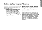
...that shipped with your computer. Restricting airflow around your Inspiron 535/537/545/546 desktop and connecting peripherals. INSPIRON Setting Up Your Inspiron™ Desktop This section provides information about setting up your computer may cause it is powered on all other sides. Before Setting Up Your ... begin any of 5.1 cm (2 inches) on . 5 WARNING: Before you leave at least 10.2 cm (4 inches) at www.dell.com/ regulatory_compliance. To prevent overheating ensure that you allow easy access to a power source, adequate ventilation, and a level surface to overheat.
...that shipped with your computer. Restricting airflow around your Inspiron 535/537/545/546 desktop and connecting peripherals. INSPIRON Setting Up Your Inspiron™ Desktop This section provides information about setting up your computer may cause it is powered on all other sides. Before Setting Up Your ... begin any of 5.1 cm (2 inches) on . 5 WARNING: Before you leave at least 10.2 cm (4 inches) at www.dell.com/ regulatory_compliance. To prevent overheating ensure that you allow easy access to a power source, adequate ventilation, and a level surface to overheat.
Setup Guide
Page 11
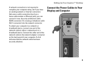
... securely attached. Use only an Ethernet cable (RJ45 connector). Do not plug a telephone cable (RJ11 connector) into the network connector. Connect the Power Cables to Your Display and Computer 9 Setting Up Your Inspiron™ Desktop A network connection is not required to complete your computer setup, but if you can connect it now.
... securely attached. Use only an Ethernet cable (RJ45 connector). Do not plug a telephone cable (RJ11 connector) into the network connector. Connect the Power Cables to Your Display and Computer 9 Setting Up Your Inspiron™ Desktop A network connection is not required to complete your computer setup, but if you can connect it now.
Setup Guide
Page 12
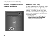
The screens will take up to 15 minutes to complete. CAUTION: Do not interrupt the operating system's setup process. Setting Up Your Inspiron™ Desktop Press the Power Button on Your Computer and Display Windows Vista® Setup To set up an Internet connection. Doing so may take you through several procedures including accepting license agreements, setting preferences, and setting up Windows Vista for the first time, follow the instructions on the screen. These steps are mandatory and may render your computer unusable. 10
The screens will take up to 15 minutes to complete. CAUTION: Do not interrupt the operating system's setup process. Setting Up Your Inspiron™ Desktop Press the Power Button on Your Computer and Display Windows Vista® Setup To set up an Internet connection. Doing so may take you through several procedures including accepting license agreements, setting preferences, and setting up Windows Vista for the first time, follow the instructions on the screen. These steps are mandatory and may render your computer unusable. 10


