
Specifications (SWF/PDF)
Page 3
Contents 1 Before You Begin 9 Recommended Tools 9 Turning Off Your Computer 9 Before Working Inside Your Computer 10 2 Battery 13 Removing the Battery 13 Replacing the Battery 14 3 Keyboard 15 Removing the Keyboard 15 Replacing the Keyboard 17 4 Memory Module(s 19 Removing the Memory Module(s 19 Replacing the Memory Module(s 20 5 Optical Drive 23 Removing the Optical Drive 23 Contents 3
Contents 1 Before You Begin 9 Recommended Tools 9 Turning Off Your Computer 9 Before Working Inside Your Computer 10 2 Battery 13 Removing the Battery 13 Replacing the Battery 14 3 Keyboard 15 Removing the Keyboard 15 Replacing the Keyboard 17 4 Memory Module(s 19 Removing the Memory Module(s 19 Replacing the Memory Module(s 20 5 Optical Drive 23 Removing the Optical Drive 23 Contents 3

Specifications (SWF/PDF)
Page 15
...help prevent damage to servicing that is not authorized by Dell is not covered by periodically touching an unpainted metal surface (such as possible. 4 Using a plastic scribe, release the four tabs that secure the keyboard to replace. Damage due to the system board, remove ...the main battery (see the Regulatory Compliance Homepage at www.dell.com/regulatory_compliance. CAUTION: Only a certified service technician should perform repairs on page ...
...help prevent damage to servicing that is not authorized by Dell is not covered by periodically touching an unpainted metal surface (such as possible. 4 Using a plastic scribe, release the four tabs that secure the keyboard to replace. Damage due to the system board, remove ...the main battery (see the Regulatory Compliance Homepage at www.dell.com/regulatory_compliance. CAUTION: Only a certified service technician should perform repairs on page ...
Specifications (SWF/PDF)
Page 16
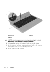
Failure to do so could result in scratching the display panel. 5 Without pulling hard on the keyboard, hold it towards the display. 6 Lift the connector latch that secures the keyboard cable to the connector on the system board and remove the keyboard cable. 7 Lift the keyboard off the computer. 16 Keyboard 1 2 3 1 plastic scribe 3 keyboard 2 tabs (4) CAUTION: Be extremely careful when removing and handling the keyboard.
Failure to do so could result in scratching the display panel. 5 Without pulling hard on the keyboard, hold it towards the display. 6 Lift the connector latch that secures the keyboard cable to the connector on the system board and remove the keyboard cable. 7 Lift the keyboard off the computer. 16 Keyboard 1 2 3 1 plastic scribe 3 keyboard 2 tabs (4) CAUTION: Be extremely careful when removing and handling the keyboard.

Specifications (SWF/PDF)
Page 17
Keyboard 17 2 1 1 keyboard cable 2 keyboard Replacing the Keyboard 1 Follow the instructions in "Before You Begin" on page 9. 2 Slide the keyboard cable into the slots on the palm rest. 4 Gently press around the edges of the keyboard to the connector on the system board. 3 Slide the tabs on the keyboard into the connector on page 14). Press down on the connector latch to secure the keyboard cable to lock the four tabs securing the keyboard. 5 Close the display and turn the computer over. 6 Replace the battery (see "Replacing the Battery" on the system board.
Keyboard 17 2 1 1 keyboard cable 2 keyboard Replacing the Keyboard 1 Follow the instructions in "Before You Begin" on page 9. 2 Slide the keyboard cable into the slots on the palm rest. 4 Gently press around the edges of the keyboard to the connector on the system board. 3 Slide the tabs on the keyboard into the connector on page 14). Press down on the connector latch to secure the keyboard cable to lock the four tabs securing the keyboard. 5 Close the display and turn the computer over. 6 Replace the battery (see "Replacing the Battery" on the system board.
Specifications (SWF/PDF)
Page 19
...Only a certified service technician should perform repairs on page 15). CAUTION: To help prevent damage to servicing that is not authorized by Dell is not covered by your computer. Your computer has two user-accessible SODIMM sockets, labeled DIMM A and DIMM B, that shipped ...Remove the battery (see "Removing the Battery" on page 13). 3 Remove the keyboard (see the Regulatory Compliance Homepage at support.dell.com/manuals. For additional safety best practices information, see "Removing the Keyboard" on your fingertips to carefully spread apart the securing clips on the system board...
...Only a certified service technician should perform repairs on page 15). CAUTION: To help prevent damage to servicing that is not authorized by Dell is not covered by your computer. Your computer has two user-accessible SODIMM sockets, labeled DIMM A and DIMM B, that shipped ...Remove the battery (see "Removing the Battery" on page 13). 3 Remove the keyboard (see the Regulatory Compliance Homepage at support.dell.com/manuals. For additional safety best practices information, see "Removing the Keyboard" on your fingertips to carefully spread apart the securing clips on the system board...

Specifications (SWF/PDF)
Page 21
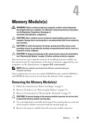
As the computer boots, it detects the memory module(s) and automatically updates the system configuration information. 2 1 1 tab 2 notch 4 Replace the keyboard (see "Replacing the Keyboard" on page 17). 5 Replace the battery (see "Replacing the Battery" on page 14), or connect the AC adapter to your computer and an electrical outlet. 6 Turn on the computer. Memory 21 To confirm the amount of memory installed in the computer: Click Start → Control Panel→ System and Security→ System.
As the computer boots, it detects the memory module(s) and automatically updates the system configuration information. 2 1 1 tab 2 notch 4 Replace the keyboard (see "Replacing the Keyboard" on page 17). 5 Replace the battery (see "Replacing the Battery" on page 14), or connect the AC adapter to your computer and an electrical outlet. 6 Turn on the computer. Memory 21 To confirm the amount of memory installed in the computer: Click Start → Control Panel→ System and Security→ System.
Specifications (SWF/PDF)
Page 23
... drive to the computer base. 5 Using a plastic scribe, push the notch on page 13). 3 Remove the keyboard (see the Regulatory Compliance Homepage at www.dell.com/regulatory_compliance. Damage due to servicing that secures the optical drive to release it from the optical-drive compartment. ...safety information that shipped with your computer. For additional safety best practices information, see "Removing the Keyboard" on page 15). 4 Remove the screw that is not authorized by Dell is not covered by periodically touching an unpainted metal surface (such as a connector on your computer...
... drive to the computer base. 5 Using a plastic scribe, push the notch on page 13). 3 Remove the keyboard (see the Regulatory Compliance Homepage at www.dell.com/regulatory_compliance. Damage due to servicing that secures the optical drive to release it from the optical-drive compartment. ...safety information that shipped with your computer. For additional safety best practices information, see "Removing the Keyboard" on page 15). 4 Remove the screw that is not authorized by Dell is not covered by periodically touching an unpainted metal surface (such as a connector on your computer...
Specifications (SWF/PDF)
Page 24
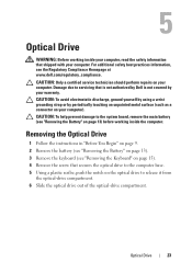
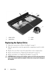
... the computer. 1 2 3 4 1 plastic scribe 3 optical drive 2 screw 4 notch Replacing the Optical Drive 1 Follow the instructions in damage to the computer base. 4 Replace the keyboard (see "Replacing the Keyboard" on page 17). 5 Replace the battery (see "Replacing the Battery" on page 14). Failure to do so may result in "Before You Begin" on...
... the computer. 1 2 3 4 1 plastic scribe 3 optical drive 2 screw 4 notch Replacing the Optical Drive 1 Follow the instructions in damage to the computer base. 4 Replace the keyboard (see "Replacing the Keyboard" on page 17). 5 Replace the battery (see "Replacing the Battery" on page 14). Failure to do so may result in "Before You Begin" on...
Specifications (SWF/PDF)
Page 26
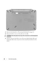
CAUTION: Pull on the plastic tab on top of the connectors to avoid damaging the connectors. 6 Lift the connector latch that secures the power-button board cable and touch-pad cable to the connectors on the palm-rest assembly. 4 Remove the keyboard (see "Removing the Keyboard" on page 15). 5 Remove the three screws on the system board and remove the cables. 26 Palm-Rest Assembly
CAUTION: Pull on the plastic tab on top of the connectors to avoid damaging the connectors. 6 Lift the connector latch that secures the power-button board cable and touch-pad cable to the connectors on the palm-rest assembly. 4 Remove the keyboard (see "Removing the Keyboard" on page 15). 5 Remove the three screws on the system board and remove the cables. 26 Palm-Rest Assembly
Specifications (SWF/PDF)
Page 28
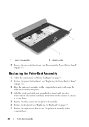
... on the system board and press down on the connector latches to secure them. 5 Replace the three screws on the palm-rest assembly. 6 Replace the keyboard (see "Removing the Power Button Board" on page 17). 7 Replace the eight screws that secure the palm-rest assembly to the computer base. 28 Palm...
... on the system board and press down on the connector latches to secure them. 5 Replace the three screws on the palm-rest assembly. 6 Replace the keyboard (see "Removing the Power Button Board" on page 17). 7 Replace the eight screws that secure the palm-rest assembly to the computer base. 28 Palm...
Specifications (SWF/PDF)
Page 73
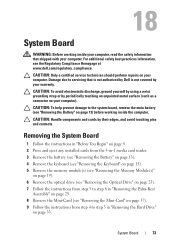
...any installed cards from the 3-in-1 media card reader. 3 Remove the battery (see "Removing the Battery" on page 13). 4 Remove the keyboard (see "Removing the Keyboard" on page 15). 5 Remove the memory module(s) (see "Removing the Memory Module(s)" on page 19). 6 Remove the optical drive (see...37). 9 Follow the instructions from step 4 to the system board, remove the main battery (see the Regulatory Compliance Homepage at www.dell.com/regulatory_compliance. CAUTION: Only a certified service technician should perform repairs on page 13) before working inside the computer. 18 System Board ...
...any installed cards from the 3-in-1 media card reader. 3 Remove the battery (see "Removing the Battery" on page 13). 4 Remove the keyboard (see "Removing the Keyboard" on page 15). 5 Remove the memory module(s) (see "Removing the Memory Module(s)" on page 19). 6 Remove the optical drive (see...37). 9 Follow the instructions from step 4 to the system board, remove the main battery (see the Regulatory Compliance Homepage at www.dell.com/regulatory_compliance. CAUTION: Only a certified service technician should perform repairs on page 13) before working inside the computer. 18 System Board ...
Specifications (SWF/PDF)
Page 76
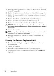
... "Replacing the Optical Drive" on page 24). 11 Replace the memory module(s) (see "Replacing the Memory Module(s)" on page 20). 12 Replace the keyboard (see "Replacing the Keyboard" on page 17). 13 Replace the battery (see "Entering the Service Tag in the BIOS" on page 76). CAUTION: Before turning on the computer...
... "Replacing the Optical Drive" on page 24). 11 Replace the memory module(s) (see "Replacing the Memory Module(s)" on page 20). 12 Replace the keyboard (see "Replacing the Keyboard" on page 17). 13 Replace the battery (see "Entering the Service Tag in the BIOS" on page 76). CAUTION: Before turning on the computer...


