
Specifications (SWF/PDF)
Page 3
Contents 1 Before You Begin 9 Recommended Tools 9 Turning Off Your Computer 9 Before Working Inside Your Computer 10 2 Battery 13 Removing the Battery 13 Replacing the Battery 14 3 Keyboard 15 Removing the Keyboard 15 Replacing the Keyboard 17 4 Memory Module(s 19 Removing the Memory Module(s 19 Replacing the Memory Module(s 20 5 Optical Drive 23 Removing the Optical Drive 23 Contents 3
Contents 1 Before You Begin 9 Recommended Tools 9 Turning Off Your Computer 9 Before Working Inside Your Computer 10 2 Battery 13 Removing the Battery 13 Replacing the Battery 14 3 Keyboard 15 Removing the Keyboard 15 Replacing the Keyboard 17 4 Memory Module(s 19 Removing the Memory Module(s 19 Replacing the Memory Module(s 20 5 Optical Drive 23 Removing the Optical Drive 23 Contents 3
Specifications (SWF/PDF)
Page 4
Replacing the Optical Drive 24 6 Palm-Rest Assembly 25 Removing the Palm-Rest Assembly 25 Replacing the Palm-Rest Assembly 28 7 Power Button Board 31 Removing the Power Button Board 31 Replacing the Power Button Board 32 8 Hard Drive 33 Removing the Hard Drive 33 Replacing the Hard Drive 35 9 Wireless Mini-Card 37 Removing the Mini-Card 37 Replacing the Mini-Card 38 10 Audio Board 41 Removing the Audio Board 41 Replacing the Audio Board 42 4 Contents
Replacing the Optical Drive 24 6 Palm-Rest Assembly 25 Removing the Palm-Rest Assembly 25 Replacing the Palm-Rest Assembly 28 7 Power Button Board 31 Removing the Power Button Board 31 Replacing the Power Button Board 32 8 Hard Drive 33 Removing the Hard Drive 33 Replacing the Hard Drive 35 9 Wireless Mini-Card 37 Removing the Mini-Card 37 Replacing the Mini-Card 38 10 Audio Board 41 Removing the Audio Board 41 Replacing the Audio Board 42 4 Contents
Specifications (SWF/PDF)
Page 5
11 Coin-Cell Battery 43 Removing the Coin-Cell Battery 43 Replacing the Coin-Cell Battery 45 12 USB Board 47 Removing the USB Board 47 Replacing the USB Board 48 13 Thermal Cooling Assembly 49 Removing the Thermal Cooling Assembly 49 Replacing the Thermal Cooling Assembly 50 14 Processor Module (For Inspiron 14-N4050 Only) 51 Removing the Processor Module 51 Replacing the Processor Module 52 15 Hinge Cover 55 Removing the Hinge Cover 55 Replacing the Hinge Cover 57 16 Display 59 Display Assembly 59 Contents 5
11 Coin-Cell Battery 43 Removing the Coin-Cell Battery 43 Replacing the Coin-Cell Battery 45 12 USB Board 47 Removing the USB Board 47 Replacing the USB Board 48 13 Thermal Cooling Assembly 49 Removing the Thermal Cooling Assembly 49 Replacing the Thermal Cooling Assembly 50 14 Processor Module (For Inspiron 14-N4050 Only) 51 Removing the Processor Module 51 Replacing the Processor Module 52 15 Hinge Cover 55 Removing the Hinge Cover 55 Replacing the Hinge Cover 57 16 Display 59 Display Assembly 59 Contents 5
Specifications (SWF/PDF)
Page 6
Removing the Display Assembly 59 Replacing the Display Assembly 61 Display Bezel 62 Removing the Display Bezel 62 Replacing the Display Bezel 63 Removing the Display Panel 63 Replacing the Display Panel 66 17 Camera Module 69 Removing the Camera Module 69 Replacing the Camera Module 70 18 System Board 73 Removing the System Board 73 Replacing the System Board 75 Entering the Service Tag in the BIOS 76 19 Flashing the BIOS 77 6 Contents
Removing the Display Assembly 59 Replacing the Display Assembly 61 Display Bezel 62 Removing the Display Bezel 62 Replacing the Display Bezel 63 Removing the Display Panel 63 Replacing the Display Panel 66 17 Camera Module 69 Removing the Camera Module 69 Replacing the Camera Module 70 18 System Board 73 Removing the System Board 73 Replacing the System Board 75 Entering the Service Tag in the BIOS 76 19 Flashing the BIOS 77 6 Contents
Specifications (SWF/PDF)
Page 10
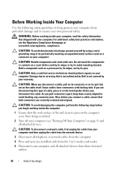
... connectors are disconnecting this type of cable, press in -1 media card reader. 5 Disconnect your computer). Do not touch the components or contacts on page 9) and all attached devices from being scratched. 2 Turn off your computer. As you begin working inside the computer. 1 Ensure that is not authorized by Dell is flat and clean to avoid bending any installed cards from the 3-in...
... connectors are disconnecting this type of cable, press in -1 media card reader. 5 Disconnect your computer). Do not touch the components or contacts on page 9) and all attached devices from being scratched. 2 Turn off your computer. As you begin working inside the computer. 1 Ensure that is not authorized by Dell is flat and clean to avoid bending any installed cards from the 3-in...
Specifications (SWF/PDF)
Page 11
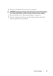
CAUTION: To help prevent damage to the system board, remove the main battery (see "Removing the Battery" on page 13) before working inside the computer. 7 Remove the battery (see "Removing the Battery" on page 13). 8 Turn the computer top-side up, open the display, and press the power button to ground the system board. 6 Disconnect all attached devices from your computer. Before You Begin 11
CAUTION: To help prevent damage to the system board, remove the main battery (see "Removing the Battery" on page 13) before working inside the computer. 7 Remove the battery (see "Removing the Battery" on page 13). 8 Turn the computer top-side up, open the display, and press the power button to ground the system board. 6 Disconnect all attached devices from your computer. Before You Begin 11

Specifications (SWF/PDF)
Page 15
... the system board, remove the main battery (see the Regulatory Compliance Homepage at www.dell.com/regulatory_compliance. 3 Keyboard WARNING: Before working inside your computer, read the safety information that is not authorized by Dell is not covered by periodically touching an unpainted metal surface (such as possible. 4 Using a plastic scribe, release the four tabs that secure the keyboard to servicing that shipped...
... the system board, remove the main battery (see the Regulatory Compliance Homepage at www.dell.com/regulatory_compliance. 3 Keyboard WARNING: Before working inside your computer, read the safety information that is not authorized by Dell is not covered by periodically touching an unpainted metal surface (such as possible. 4 Using a plastic scribe, release the four tabs that secure the keyboard to servicing that shipped...
Specifications (SWF/PDF)
Page 19
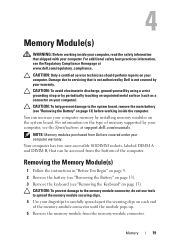
... or by installing memory modules on page 13). 3 Remove the keyboard (see the Regulatory Compliance Homepage at support.dell.com/manuals. Removing the Memory Module(s) 1 Follow the instructions in "Before You Begin" on page 9. 2 Remove the battery (see "Removing the Battery" on the system board. You can be accessed from the memory-module connector. For information on page 13) before working inside the computer. CAUTION: Only a certified service technician should perform repairs on...
... or by installing memory modules on page 13). 3 Remove the keyboard (see the Regulatory Compliance Homepage at support.dell.com/manuals. Removing the Memory Module(s) 1 Follow the instructions in "Before You Begin" on page 9. 2 Remove the battery (see "Removing the Battery" on the system board. You can be accessed from the memory-module connector. For information on page 13) before working inside the computer. CAUTION: Only a certified service technician should perform repairs on...
Specifications (SWF/PDF)
Page 20
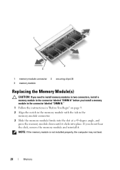
... install a memory module in the connector labeled "DIMM B." 1 Follow the instructions in "Before You Begin" on page 9. 2 Align the notch in the memory module with the tab in the memory-module connector. 3 Slide the memory module firmly into the slot at a 45-degree angle, and press the memory module down until it . 1 3 2 1 memory-module connector 2 securing clips (2) 3 memory module Replacing the Memory Module(s) CAUTION: If you need to install memory modules in two connectors, install a memory module...
... install a memory module in the connector labeled "DIMM B." 1 Follow the instructions in "Before You Begin" on page 9. 2 Align the notch in the memory module with the tab in the memory-module connector. 3 Slide the memory module firmly into the slot at a 45-degree angle, and press the memory module down until it . 1 3 2 1 memory-module connector 2 securing clips (2) 3 memory module Replacing the Memory Module(s) CAUTION: If you need to install memory modules in two connectors, install a memory module...
Specifications (SWF/PDF)
Page 33
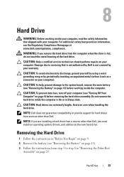
... install an operating system, drivers, and utilities on your computer). CAUTION: Only a certified service technician should perform repairs on page 9) before working inside the computer. NOTE: If you are extremely fragile. For additional safety best practices information, see "Turning Off Your Computer" on your computer. NOTE: Dell does not guarantee compatibility or provide support for hard drives from step 3 to the system board, remove...
... install an operating system, drivers, and utilities on your computer). CAUTION: Only a certified service technician should perform repairs on page 9) before working inside the computer. NOTE: If you are extremely fragile. For additional safety best practices information, see "Turning Off Your Computer" on your computer. NOTE: Dell does not guarantee compatibility or provide support for hard drives from step 3 to the system board, remove...
Specifications (SWF/PDF)
Page 35
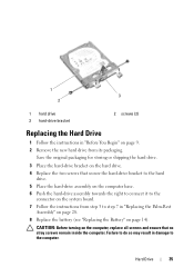
... to step 7 in "Before You Begin" on page 9. 2 Remove the new hard drive from step 3 to the computer. CAUTION: Before turning on the computer, replace all screws and ensure that secure the hard-drive bracket to the hard drive. 5 Place the hard-drive assembly on the computer base. 6 Push the hard-drive assembly towards the right to connect it to the connector on the system...
... to step 7 in "Before You Begin" on page 9. 2 Remove the new hard drive from step 3 to the computer. CAUTION: Before turning on the computer, replace all screws and ensure that secure the hard-drive bracket to the hard drive. 5 Place the hard-drive assembly on the computer base. 6 Push the hard-drive assembly towards the right to connect it to the connector on the system...
Specifications (SWF/PDF)
Page 38
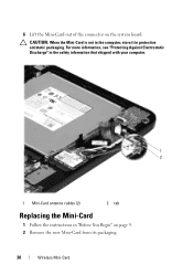
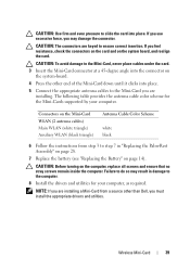
6 Lift the Mini-Card out of the connector on page 9. 2 Remove the new Mini-Card from its packaging. 38 Wireless Mini-Card For more information, see "Protecting Against Electrostatic Discharge" in the safety information that shipped with your computer. 1 2 1 Mini-Card antenna cables (2) 2 tab Replacing the Mini-Card 1 Follow the instructions in protective antistatic packaging. CAUTION: When the Mini-Card is not in the computer, store it in "Before You Begin" on the system board.
6 Lift the Mini-Card out of the connector on page 9. 2 Remove the new Mini-Card from its packaging. 38 Wireless Mini-Card For more information, see "Protecting Against Electrostatic Discharge" in the safety information that shipped with your computer. 1 2 1 Mini-Card antenna cables (2) 2 tab Replacing the Mini-Card 1 Follow the instructions in protective antistatic packaging. CAUTION: When the Mini-Card is not in the computer, store it in "Before You Begin" on the system board.
Specifications (SWF/PDF)
Page 39
If you use excessive force, you may result in "Replacing the Palm-Rest Assembly" on page 28. 7 Replace the battery (see "Replacing the Battery" on page 14). Wireless Mini-Card 39 Connectors on the system-board. 4 Press the other than Dell, you must install the appropriate drivers and utilities. CAUTION: The connectors are installing. Failure to do so may damage the connector. CAUTION: To avoid...
If you use excessive force, you may result in "Replacing the Palm-Rest Assembly" on page 28. 7 Replace the battery (see "Replacing the Battery" on page 14). Wireless Mini-Card 39 Connectors on the system-board. 4 Press the other than Dell, you must install the appropriate drivers and utilities. CAUTION: The connectors are installing. Failure to do so may damage the connector. CAUTION: To avoid...
Specifications (SWF/PDF)
Page 48
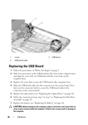
... USB-board cable to the connector on the system board. 5 Replace the optical drive (see "Replacing the Optical Drive" on page 24). 6 Follow the instructions from step 3 to the computer. 48 USB Board Failure to do so may result in damage to step 7 in "Before You Begin" on page 9. 2 Slide the connectors on the USB board into the connector on the system board. 1 2 3 1 screw 3 USB-board cable 2 USB board Replacing...
... USB-board cable to the connector on the system board. 5 Replace the optical drive (see "Replacing the Optical Drive" on page 24). 6 Follow the instructions from step 3 to the computer. 48 USB Board Failure to do so may result in damage to step 7 in "Before You Begin" on page 9. 2 Slide the connectors on the USB board into the connector on the system board. 1 2 3 1 screw 3 USB-board cable 2 USB board Replacing...
Specifications (SWF/PDF)
Page 51
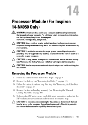
... Dell is not covered by your warranty. CAUTION: Handle components and cards by their edges, and avoid touching pins and contacts. Processor Module (For Inspiron 14-N4050 Only) 51 For additional safety best practices information, see "Removing the Battery" on the processor thermal cooling assembly. Removing the Processor Module 1 Follow the instructions in "Before You Begin" on page 9. 2 Remove the battery (see "Removing the Battery...
... Dell is not covered by your warranty. CAUTION: Handle components and cards by their edges, and avoid touching pins and contacts. Processor Module (For Inspiron 14-N4050 Only) 51 For additional safety best practices information, see "Removing the Battery" on the processor thermal cooling assembly. Removing the Processor Module 1 Follow the instructions in "Before You Begin" on page 9. 2 Remove the battery (see "Removing the Battery...
Specifications (SWF/PDF)
Page 57
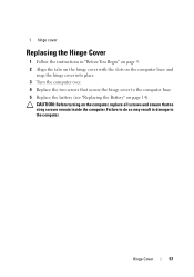
Failure to do so may result in "Before You Begin" on page 9. 2 Align the tabs on the hinge cover with the slots on the computer base and snap the hinge cover into place. 3 Turn the computer over. 4 Replace the two screws that secure the hinge cover to the computer. 1 hinge cover Replacing the Hinge Cover 1 Follow the instructions in damage to the computer base. 5 Replace the battery (see "Replacing the Battery" on the computer, replace all screws and ensure that no stray screws remain inside the computer. CAUTION: Before turning on page 14). Hinge Cover 57
Failure to do so may result in "Before You Begin" on page 9. 2 Align the tabs on the hinge cover with the slots on the computer base and snap the hinge cover into place. 3 Turn the computer over. 4 Replace the two screws that secure the hinge cover to the computer. 1 hinge cover Replacing the Hinge Cover 1 Follow the instructions in damage to the computer base. 5 Replace the battery (see "Replacing the Battery" on the computer, replace all screws and ensure that no stray screws remain inside the computer. CAUTION: Before turning on page 14). Hinge Cover 57
Specifications (SWF/PDF)
Page 63
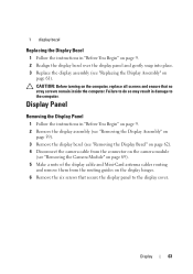
... the display cover. Failure to do so may result in "Before You Begin" on page 9. 2 Realign the display bezel over the display panel and gently snap into place. 3 Replace the display assembly (see "Removing the Camera Module" on page 69). 5 Make a note of the display cable and Mini-Card antenna cables routing and remove them from the routing guides on page 61). 1 display bezel Replacing the Display Bezel 1 Follow the instructions...
... the display cover. Failure to do so may result in "Before You Begin" on page 9. 2 Realign the display bezel over the display panel and gently snap into place. 3 Replace the display assembly (see "Removing the Camera Module" on page 69). 5 Make a note of the display cable and Mini-Card antenna cables routing and remove them from the routing guides on page 61). 1 display bezel Replacing the Display Bezel 1 Follow the instructions...
Specifications (SWF/PDF)
Page 69
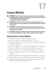
... service technician should perform repairs on your computer. CAUTION: To help prevent damage to the system board, remove the main battery (see the Regulatory Compliance Homepage at www.dell.com/regulatory_compliance. Camera Module 69 For additional safety best practices information, see "Removing the Battery" on page 13) before working inside the computer. Damage due to the display cover and lift the camera module off the display cover...
... service technician should perform repairs on your computer. CAUTION: To help prevent damage to the system board, remove the main battery (see the Regulatory Compliance Homepage at www.dell.com/regulatory_compliance. Camera Module 69 For additional safety best practices information, see "Removing the Battery" on page 13) before working inside the computer. Damage due to the display cover and lift the camera module off the display cover...
Specifications (SWF/PDF)
Page 73
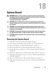
... any installed cards from the 3-in-1 media card reader. 3 Remove the battery (see "Removing the Battery" on page 13). 4 Remove the keyboard (see "Removing the Keyboard" on page 15). 5 Remove the memory module(s) (see "Removing the Memory Module(s)" on page 19). 6 Remove the optical drive (see "Removing the Optical Drive" on page 23). 7 Follow the instructions from step 3 to the system board, remove the main battery (see "Removing the Battery" on your computer). CAUTION: Only a certified service technician should perform repairs...
... any installed cards from the 3-in-1 media card reader. 3 Remove the battery (see "Removing the Battery" on page 13). 4 Remove the keyboard (see "Removing the Keyboard" on page 15). 5 Remove the memory module(s) (see "Removing the Memory Module(s)" on page 19). 6 Remove the optical drive (see "Removing the Optical Drive" on page 23). 7 Follow the instructions from step 3 to the system board, remove the main battery (see "Removing the Battery" on your computer). CAUTION: Only a certified service technician should perform repairs...
Specifications (SWF/PDF)
Page 76
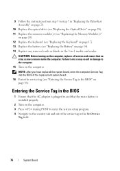
... the Set Service Tag field. 76 System Board 9 Follow the instructions from step 3 to step 7 in "Replacing the Palm-Rest Assembly" on page 28. 10 Replace the optical drive (see "Replacing the Optical Drive" on page 24). 11 Replace the memory module(s) (see "Replacing the Memory Module(s)" on page 20). 12 Replace the keyboard (see "Replacing the Keyboard" on page 17). 13 Replace the battery (see "Entering the Service Tag in the BIOS" on...
... the Set Service Tag field. 76 System Board 9 Follow the instructions from step 3 to step 7 in "Replacing the Palm-Rest Assembly" on page 28. 10 Replace the optical drive (see "Replacing the Optical Drive" on page 24). 11 Replace the memory module(s) (see "Replacing the Memory Module(s)" on page 20). 12 Replace the keyboard (see "Replacing the Keyboard" on page 17). 13 Replace the battery (see "Entering the Service Tag in the BIOS" on...


