Specifications
Page 3
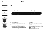
... to 5 Gbps. 5 Media-card reader Reads from a router or a broadband modem for network or internet access. Specifications Views Front Left Left 1 2 3 4 5 Right Base Display 1 Power-adapter port Connect a power adapter to provide power to your computer and charge the battery. 2 Network port Connect an Ethernet (RJ45) cable from and writes to media cards. The two lights next to the port indicate the connectivity status and network activity. 3 HDMI port Connect a TV or another HDMI‑in enabled device. Provides video and audio output. 4 USB 3.0 port Connect peripherals such as...
... to 5 Gbps. 5 Media-card reader Reads from a router or a broadband modem for network or internet access. Specifications Views Front Left Left 1 2 3 4 5 Right Base Display 1 Power-adapter port Connect a power adapter to provide power to your computer and charge the battery. 2 Network port Connect an Ethernet (RJ45) cable from and writes to media cards. The two lights next to the port indicate the connectivity status and network activity. 3 HDMI port Connect a TV or another HDMI‑in enabled device. Provides video and audio output. 4 USB 3.0 port Connect peripherals such as...
Specifications
Page 8
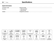
Views System information Computer model Processor Chipset Specifications Inspiron 17-5755 • AMD A10-8700P • AMD A8-7410 Integrated in processor Dimensions and weight System information Memory Ports and connectors Communications Video Audio Storage Media-card reader Display Keyboard Camera Touch pad Battery Power adapter Computer environment
Views System information Computer model Processor Chipset Specifications Inspiron 17-5755 • AMD A10-8700P • AMD A8-7410 Integrated in processor Dimensions and weight System information Memory Ports and connectors Communications Video Audio Storage Media-card reader Display Keyboard Camera Touch pad Battery Power adapter Computer environment
Specifications
Page 17
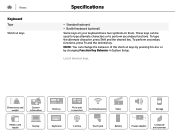
... can be used to type alternate characters or to perform secondary functions. List of the shortcut keys by pressing Fn+Esc or by changing Function Key Behavior in System Setup. To type the alternate character, press Shift and the desired key. Dimensions and weight System information Memory Ports and connectors Communications Video Audio Storage Media-card reader Display Keyboard Camera Touch pad Battery Power adapter Computer environment Views Keyboard Type Shortcut keys Specifications • Standard keyboard • Backlit keyboard (optional) Some keys on your...
... can be used to type alternate characters or to perform secondary functions. List of the shortcut keys by pressing Fn+Esc or by changing Function Key Behavior in System Setup. To type the alternate character, press Shift and the desired key. Dimensions and weight System information Memory Ports and connectors Communications Video Audio Storage Media-card reader Display Keyboard Camera Touch pad Battery Power adapter Computer environment Views Keyboard Type Shortcut keys Specifications • Standard keyboard • Backlit keyboard (optional) Some keys on your...
Specifications
Page 18
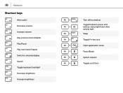
Keyboard Shortcut keys Mute audio Decrease volume Increase volume Play previous track/chapter Play/Pause Play next track/chapter Switch to external display Search Toggle keyboard backlight Decrease brightness Increase brightness Turn off/on wireless Toggle between power and battery-status light/hard-drive activity light Sleep Toggle Fn-key lock Open application menu Pause/Break System request Toggle scroll lock
Keyboard Shortcut keys Mute audio Decrease volume Increase volume Play previous track/chapter Play/Pause Play next track/chapter Switch to external display Search Toggle keyboard backlight Decrease brightness Increase brightness Turn off/on wireless Toggle between power and battery-status light/hard-drive activity light Sleep Toggle Fn-key lock Open application menu Pause/Break System request Toggle scroll lock
Service Manual
Page 4
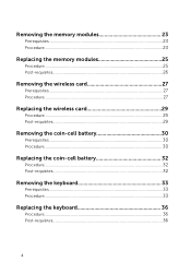
Removing the memory modules 23 Prerequisites...23 Procedure...23 Replacing the memory modules 25 Procedure...25 Post-requisites 26 Removing the wireless card 27 Prerequisites...27 Procedure...27 Replacing the wireless card 29 Procedure...29 Post-requisites 29 Removing the coin-cell battery 30 Prerequisites...30 Procedure...30 Replacing the coin-cell battery 32 Procedure...32 Post-requisites 32 Removing the keyboard 33 Prerequisites...33 Procedure...33 Replacing the keyboard 36 Procedure...36 Post-requisites 36 4
Removing the memory modules 23 Prerequisites...23 Procedure...23 Replacing the memory modules 25 Procedure...25 Post-requisites 26 Removing the wireless card 27 Prerequisites...27 Procedure...27 Replacing the wireless card 29 Procedure...29 Post-requisites 29 Removing the coin-cell battery 30 Prerequisites...30 Procedure...30 Replacing the coin-cell battery 32 Procedure...32 Post-requisites 32 Removing the keyboard 33 Prerequisites...33 Procedure...33 Replacing the keyboard 36 Procedure...36 Post-requisites 36 4
Service Manual
Page 10
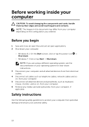
... computer. 6 Remove any media card and optical disc from your computer, if applicable. Before working inside your computer CAUTION: To avoid damaging the components and cards, handle them by their electrical outlets. 4 Disconnect all cables such as telephone cables, network cables and so on, from your computer. 5 Disconnect all attached devices and peripherals, such as keyboard, mouse, monitor, and so on the configuration you begin...
... computer. 6 Remove any media card and optical disc from your computer, if applicable. Before working inside your computer CAUTION: To avoid damaging the components and cards, handle them by their electrical outlets. 4 Disconnect all cables such as telephone cables, network cables and so on, from your computer. 5 Disconnect all attached devices and peripherals, such as keyboard, mouse, monitor, and so on the configuration you begin...

Service Manual
Page 11
... on the cable itself. WARNING: Before working inside the computer, replace all power sources before opening the computer cover or panels. When connecting cables, ensure that is not authorized by your computer and then unplug the cable from the media-card reader. When disconnecting cables, keep them by the Dell technical assistance team. CAUTION: You should only perform troubleshooting and repairs as the metal at dell.com/regulatory_compliance...
... on the cable itself. WARNING: Before working inside the computer, replace all power sources before opening the computer cover or panels. When connecting cables, ensure that is not authorized by your computer and then unplug the cable from the media-card reader. When disconnecting cables, keep them by the Dell technical assistance team. CAUTION: You should only perform troubleshooting and repairs as the metal at dell.com/regulatory_compliance...
Service Manual
Page 13
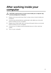
After working inside your computer CAUTION: Leaving stray or loose screws inside your computer may severely damage your computer. 1 Replace all screws and ensure that no stray screws remain inside your computer. 2 Connect any external devices, peripherals, and cables you removed before working on your computer. 3 Replace any media cards, discs, and any other parts that you removed before working on your computer. 4 Connect your computer and all attached devices to their electrical outlets. 5 Turn on your computer. 13
After working inside your computer CAUTION: Leaving stray or loose screws inside your computer may severely damage your computer. 1 Replace all screws and ensure that no stray screws remain inside your computer. 2 Connect any external devices, peripherals, and cables you removed before working on your computer. 3 Replace any media cards, discs, and any other parts that you removed before working on your computer. 4 Connect your computer and all attached devices to their electrical outlets. 5 Turn on your computer. 13
Service Manual
Page 23
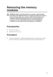
... of the memory-module slot until the memory module pops up. 23 For more safety best practices, see the Regulatory Compliance home page at dell.com/regulatory_compliance. Prerequisites 1 Remove the battery. 2 Remove the base cover. Procedure 1 Use your computer. Removing the memory modules WARNING: Before working inside your computer, read the safety information that shipped with your computer and follow the instructions in Before working inside your...
... of the memory-module slot until the memory module pops up. 23 For more safety best practices, see the Regulatory Compliance home page at dell.com/regulatory_compliance. Prerequisites 1 Remove the battery. 2 Remove the base cover. Procedure 1 Use your computer. Removing the memory modules WARNING: Before working inside your computer, read the safety information that shipped with your computer and follow the instructions in Before working inside your...
Service Manual
Page 26
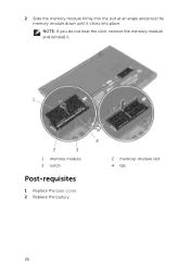
NOTE: If you do not hear the click, remove the memory module and reinstall it clicks into the slot at an angle and press the memory module down until it . 1 memory module 3 notch Post-requisites 1 Replace the base cover. 2 Replace the battery. 2 memory-module slot 4 tab 26 2 Slide the memory module firmly into place.
NOTE: If you do not hear the click, remove the memory module and reinstall it clicks into the slot at an angle and press the memory module down until it . 1 memory module 3 notch Post-requisites 1 Replace the base cover. 2 Replace the battery. 2 memory-module slot 4 tab 26 2 Slide the memory module firmly into place.
Service Manual
Page 30
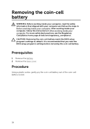
...-cell battery resets the BIOS setup program's settings to default. Prerequisites 1 Remove the battery. 2 Remove the base cover. For more safety best practices, see the Regulatory Compliance home page at dell.com/regulatory_compliance. Procedure Using a plastic scribe, gently pry the coin-cell battery out of the coin-cell battery socket. 30 It is recommended that shipped with your computer and follow the instructions in Before working...
...-cell battery resets the BIOS setup program's settings to default. Prerequisites 1 Remove the battery. 2 Remove the base cover. For more safety best practices, see the Regulatory Compliance home page at dell.com/regulatory_compliance. Procedure Using a plastic scribe, gently pry the coin-cell battery out of the coin-cell battery socket. 30 It is recommended that shipped with your computer and follow the instructions in Before working...
Service Manual
Page 60
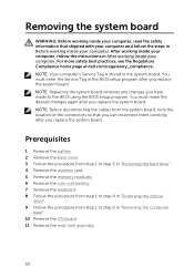
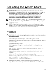
... hard drive". 4 Remove the wireless card. 5 Remove the memory modules. 6 Remove the coin-cell battery. 7 Remove the keyboard. 8 Follow the procedure from step 1 to step 4 in "Removing the optical drive". 9 Follow the procedure from the system board, note the location of the connectors so that shipped with your computer and follow the instructions in After working inside your computer. NOTE: Before disconnecting the cables from step 1 to the BIOS using the BIOS setup...
... hard drive". 4 Remove the wireless card. 5 Remove the memory modules. 6 Remove the coin-cell battery. 7 Remove the keyboard. 8 Follow the procedure from step 1 to step 4 in "Removing the optical drive". 9 Follow the procedure from the system board, note the location of the connectors so that shipped with your computer and follow the instructions in After working inside your computer. NOTE: Before disconnecting the cables from step 1 to the BIOS using the BIOS setup...
Service Manual
Page 65
... the power-button board cable and touchpad cable into the slots on the palm-rest assembly. 5 Align the screw hole on the system board with the screw hole on the palm-rest assembly. 6 Replace the screw that shipped with your computer and follow the instructions in the system board. You must make the desired changes again after you have made to the BIOS using the BIOS setup...
... the power-button board cable and touchpad cable into the slots on the palm-rest assembly. 5 Align the screw hole on the system board with the screw hole on the palm-rest assembly. 6 Replace the screw that shipped with your computer and follow the instructions in the system board. You must make the desired changes again after you have made to the BIOS using the BIOS setup...
Service Manual
Page 67
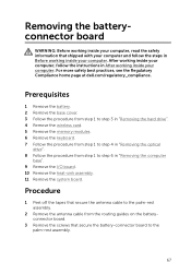
Prerequisites 1 Remove the battery. 2 Remove the base cover. 3 Follow the procedure from step 1 to step 3 in "Removing the hard drive". 4 Remove the wireless card. 5 Remove the memory modules. 6 Remove the keyboard. 7 Follow the procedure from step 1 to step 4 in "Removing the optical drive". 8 Follow the procedure from the routing guides on the batteryconnector board. 3 Remove the screws that shipped with your computer and follow the instructions in After working inside your computer. Removing the...
Prerequisites 1 Remove the battery. 2 Remove the base cover. 3 Follow the procedure from step 1 to step 3 in "Removing the hard drive". 4 Remove the wireless card. 5 Remove the memory modules. 6 Remove the keyboard. 7 Follow the procedure from step 1 to step 4 in "Removing the optical drive". 8 Follow the procedure from the routing guides on the batteryconnector board. 3 Remove the screws that shipped with your computer and follow the instructions in After working inside your computer. Removing the...
Service Manual
Page 70
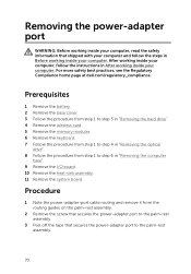
... "Removing the hard drive". 4 Remove the wireless card. 5 Remove the memory modules. 6 Remove the keyboard. 7 Follow the procedure from step 1 to step 4 in "Removing the optical drive". 8 Follow the procedure from the routing guides on the palm-rest assembly. 2 Remove the screw that secures the power-adapter port to the palm-rest assembly. 3 Peel off the tape that shipped with your computer and follow the instructions in After working inside...
... "Removing the hard drive". 4 Remove the wireless card. 5 Remove the memory modules. 6 Remove the keyboard. 7 Follow the procedure from step 1 to step 4 in "Removing the optical drive". 8 Follow the procedure from the routing guides on the palm-rest assembly. 2 Remove the screw that secures the power-adapter port to the palm-rest assembly. 3 Peel off the tape that shipped with your computer and follow the instructions in After working inside...
Service Manual
Page 73
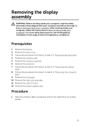
Prerequisites 1 Remove the battery. 2 Remove the base cover. 3 Follow the procedure from step 1 to step 3 in "Removing the hard drive". 4 Remove the wireless card. 5 Remove the memory modules. 6 Remove the keyboard. 7 Follow the procedure from step 1 to step 4 in "Removing the optical drive". 8 Follow the procedure from its routing guides. 73 Procedure 1 Note the antenna cable routing and remove the cable from step 1 to step 6 in After working inside your computer. For more...
Prerequisites 1 Remove the battery. 2 Remove the base cover. 3 Follow the procedure from step 1 to step 3 in "Removing the hard drive". 4 Remove the wireless card. 5 Remove the memory modules. 6 Remove the keyboard. 7 Follow the procedure from step 1 to step 4 in "Removing the optical drive". 8 Follow the procedure from its routing guides. 73 Procedure 1 Note the antenna cable routing and remove the cable from step 1 to step 6 in After working inside your computer. For more...
Service Manual
Page 78
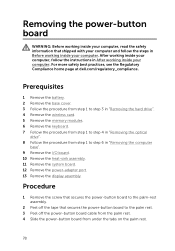
.... Removing the power-button board WARNING: Before working inside your computer, read the safety information that secures the power-button board to the palm rest. 3 Peel off the tape that shipped with your computer and follow the instructions in After working inside your computer. Prerequisites 1 Remove the battery. 2 Remove the base cover. 3 Follow the procedure from step 1 to step 3 in "Removing the hard drive". 4 Remove the wireless card. 5 Remove the memory modules. 6 Remove the keyboard...
.... Removing the power-button board WARNING: Before working inside your computer, read the safety information that secures the power-button board to the palm rest. 3 Peel off the tape that shipped with your computer and follow the instructions in After working inside your computer. Prerequisites 1 Remove the battery. 2 Remove the base cover. 3 Follow the procedure from step 1 to step 3 in "Removing the hard drive". 4 Remove the wireless card. 5 Remove the memory modules. 6 Remove the keyboard...
Service Manual
Page 85
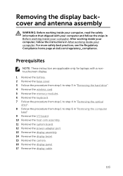
... nontouchscreen display. 1 Remove the battery. 2 Remove the base cover. 3 Follow the procedure from step 1 to step 3 in "Removing the hard drive". 4 Remove the wireless card. 5 Remove the memory modules. 6 Remove the keyboard. 7 Follow the procedure from step 1 to step 4 in "Removing the optical drive". 8 Follow the procedure from step 1 to step 6 in "Removing the computer base". 9 Remove the I/O board. 10 Remove the heat-sink assembly. 11 Remove the system board. 12 Remove the power-adapter port. 13 Remove the display...
... nontouchscreen display. 1 Remove the battery. 2 Remove the base cover. 3 Follow the procedure from step 1 to step 3 in "Removing the hard drive". 4 Remove the wireless card. 5 Remove the memory modules. 6 Remove the keyboard. 7 Follow the procedure from step 1 to step 4 in "Removing the optical drive". 8 Follow the procedure from step 1 to step 6 in "Removing the computer base". 9 Remove the I/O board. 10 Remove the heat-sink assembly. 11 Remove the system board. 12 Remove the power-adapter port. 13 Remove the display...
Service Manual
Page 88
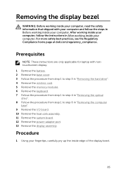
... dell.com/regulatory_compliance. Procedure 1 Remove the screws that shipped with a nontouch screen display. 1 Remove the battery. 2 Remove the base cover. 3 Follow the procedure from step 1 to step 3 in "Removing the hard drive". 4 Remove the wireless card. 5 Remove the memory modules. 6 Remove the keyboard. 7 Follow the procedure from step 1 to step 4 in "Removing the optical drive". 8 Follow the procedure from step 1 to the display backcover. 88 Prerequisites NOTE: These instructions are applicable only for laptops...
... dell.com/regulatory_compliance. Procedure 1 Remove the screws that shipped with a nontouch screen display. 1 Remove the battery. 2 Remove the base cover. 3 Follow the procedure from step 1 to step 3 in "Removing the hard drive". 4 Remove the wireless card. 5 Remove the memory modules. 6 Remove the keyboard. 7 Follow the procedure from step 1 to step 4 in "Removing the optical drive". 8 Follow the procedure from step 1 to the display backcover. 88 Prerequisites NOTE: These instructions are applicable only for laptops...
Service Manual
Page 103
... 3 in "Removing the hard drive". 4 Remove the wireless card. 5 Remove the memory modules. 6 Remove the keyboard. 7 Follow the procedure from step 1 to step 4 in "Removing the optical drive". 8 Follow the procedure from step 1 to step 6 in "Removing the computer base". 9 Remove the I/O board. 10 Remove the heat-sink assembly. 11 Remove the system board. 12 Remove the power-adapter port. 13 Remove the display assembly. 14 Remove the display bezel. 15 Remove the camera. 16 Remove the display panel. 17 Remove the display cable. 103 For...
... 3 in "Removing the hard drive". 4 Remove the wireless card. 5 Remove the memory modules. 6 Remove the keyboard. 7 Follow the procedure from step 1 to step 4 in "Removing the optical drive". 8 Follow the procedure from step 1 to step 6 in "Removing the computer base". 9 Remove the I/O board. 10 Remove the heat-sink assembly. 11 Remove the system board. 12 Remove the power-adapter port. 13 Remove the display assembly. 14 Remove the display bezel. 15 Remove the camera. 16 Remove the display panel. 17 Remove the display cable. 103 For...


