
Service Manual
Page 3
Contents 1 Before You Begin 9 Recommended Tools 9 Turning Off Your Computer 9 Before Working Inside Your Computer 10 2 Top Cover 13 Removing the Top Cover 13 Replacing the Top Cover 14 3 Battery 15 Removing the Battery 15 Replacing the Battery 16 4 Module Cover 17 Removing the Module Cover 17 Replacing the Module Cover 18 5 Memory Module(s 19 Removing the Memory Module(s 19 Contents 3
Contents 1 Before You Begin 9 Recommended Tools 9 Turning Off Your Computer 9 Before Working Inside Your Computer 10 2 Top Cover 13 Removing the Top Cover 13 Replacing the Top Cover 14 3 Battery 15 Removing the Battery 15 Replacing the Battery 16 4 Module Cover 17 Removing the Module Cover 17 Replacing the Module Cover 18 5 Memory Module(s 19 Removing the Memory Module(s 19 Contents 3

Service Manual
Page 5
... Display Cable 49 Display-Panel Brackets 50 Removing the Display-Panel Brackets 50 Replacing the Display-Panel Brackets 50 11 Hinge Cover 53 Removing the Hinge Cover 53 Replacing the Hinge Cover 55 12 Camera Module 57 Removing the Camera Module 57 Replacing the Camera Module 58 13 Coin-Cell Battery 61 Removing...
... Display Cable 49 Display-Panel Brackets 50 Removing the Display-Panel Brackets 50 Replacing the Display-Panel Brackets 50 11 Hinge Cover 53 Removing the Hinge Cover 53 Replacing the Hinge Cover 55 12 Camera Module 57 Removing the Camera Module 57 Replacing the Camera Module 58 13 Coin-Cell Battery 61 Removing...
Service Manual
Page 10
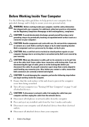
... edges or by its pull-tab, not on the cable itself. Damage due to servicing that is not authorized by Dell is flat and clean to prevent the computer cover from your computer. As you disconnect a cable, pull on its connector or on page 9) and all attached devices... from being scratched. 2 Turn off your computer (see the Regulatory Compliance Homepage at dell.com/regulatory_compliance. Hold a component such as a connector on...
... edges or by its pull-tab, not on the cable itself. Damage due to servicing that is not authorized by Dell is flat and clean to prevent the computer cover from your computer. As you disconnect a cable, pull on its connector or on page 9) and all attached devices... from being scratched. 2 Turn off your computer (see the Regulatory Compliance Homepage at dell.com/regulatory_compliance. Hold a component such as a connector on...

Service Manual
Page 13
...: Before working inside your computer, read the safety information that secures the top cover to the system board, remove the main battery (see the Regulatory Compliance Homepage at dell.com/regulatory_compliance. Removing the Top Cover 1 Follow the instructions in "Before You Begin" on your computer. Damage due to ...servicing that is not authorized by Dell is not covered by periodically touching an unpainted metal surface (such as a connector on page 9. 2 Press and hold the release button that shipped with ...
...: Before working inside your computer, read the safety information that secures the top cover to the system board, remove the main battery (see the Regulatory Compliance Homepage at dell.com/regulatory_compliance. Removing the Top Cover 1 Follow the instructions in "Before You Begin" on your computer. Damage due to ...servicing that is not authorized by Dell is not covered by periodically touching an unpainted metal surface (such as a connector on page 9. 2 Press and hold the release button that shipped with ...

Service Manual
Page 14
...1 2 1 top cover 2 release button Replacing the Top Cover 1 Follow the instructions in damage to the display back cover. 3 Slide the top cover until it clicks into place. NOTE: Ensure that the DELL logo is facing towards the back of the computer while replacing the top cover. 2 Align the top cover to the computer. ...14 Top Cover Failure to do so may result ...
...1 2 1 top cover 2 release button Replacing the Top Cover 1 Follow the instructions in damage to the display back cover. 3 Slide the top cover until it clicks into place. NOTE: Ensure that the DELL logo is facing towards the back of the computer while replacing the top cover. 2 Align the top cover to the computer. ...14 Top Cover Failure to do so may result ...

Service Manual
Page 15
... Slide and lift the battery out of the battery bay. For additional safety best practices information, see the Regulatory Compliance Homepage at dell.com/regulatory_compliance. Removing the Battery 1 Follow the instructions in "Before You Begin" on your computer. Do not use only the battery ...servicing that shipped with your computer). 3 Battery WARNING: Before working inside your computer, read the safety information that is not authorized by Dell is not covered by periodically touching an unpainted metal surface (such as a connector on page 9. 2 Shut down the computer and turn it over. 3...
... Slide and lift the battery out of the battery bay. For additional safety best practices information, see the Regulatory Compliance Homepage at dell.com/regulatory_compliance. Removing the Battery 1 Follow the instructions in "Before You Begin" on your computer. Do not use only the battery ...servicing that shipped with your computer). 3 Battery WARNING: Before working inside your computer, read the safety information that is not authorized by Dell is not covered by periodically touching an unpainted metal surface (such as a connector on page 9. 2 Shut down the computer and turn it over. 3...

Service Manual
Page 17
...board, remove the main battery (see the Regulatory Compliance Homepage at dell.com/regulatory_compliance. CAUTION: To avoid electrostatic discharge, ground yourself by using a wrist grounding strap or by your warranty. Removing the Module Cover 1 Follow the instructions in "Before You Begin" on page 9.... 15). 3 Loosen the captive screw that is not authorized by Dell™ is not covered by periodically touching an unpainted metal surface (such as a connector on the computer base. 5 Lift the module cover off the computer base. CAUTION: Only a certified service technician should...
...board, remove the main battery (see the Regulatory Compliance Homepage at dell.com/regulatory_compliance. CAUTION: To avoid electrostatic discharge, ground yourself by using a wrist grounding strap or by your warranty. Removing the Module Cover 1 Follow the instructions in "Before You Begin" on page 9.... 15). 3 Loosen the captive screw that is not authorized by Dell™ is not covered by periodically touching an unpainted metal surface (such as a connector on the computer base. 5 Lift the module cover off the computer base. CAUTION: Only a certified service technician should...

Service Manual
Page 18
3 2 1 1 tabs 3 captive screw 2 module cover Replacing the Module Cover CAUTION: To avoid damage to the computer, use only the battery designed for this particular Dell computer. 1 Follow the instructions in "Before You Begin" on page 9. 2 Align the tabs on the module cover with the slots on the computer base and snap the module cover into place. 3 Tighten the captive screw that secures the module cover to the computer base. 4 Replace the battery (see "Replacing the Battery" on page 16). 18 Module Cover
3 2 1 1 tabs 3 captive screw 2 module cover Replacing the Module Cover CAUTION: To avoid damage to the computer, use only the battery designed for this particular Dell computer. 1 Follow the instructions in "Before You Begin" on page 9. 2 Align the tabs on the module cover with the slots on the computer base and snap the module cover into place. 3 Tighten the captive screw that secures the module cover to the computer base. 4 Replace the battery (see "Replacing the Battery" on page 16). 18 Module Cover

Service Manual
Page 19
...practices information, see "Removing the Battery" on page 15) before working inside the computer. Damage due to servicing that is not authorized by Dell is not covered by your computer). See "Specifications" in "Before You Begin" on page 9. 2 Remove the battery (see "Removing the Battery" on... page 15). 3 Remove the module cover (see "Removing the Module Cover" on page 17). Memory 19 You can be accessed from the bottom of the computer. CAUTION: To avoid electrostatic discharge, ground yourself...
...practices information, see "Removing the Battery" on page 15) before working inside the computer. Damage due to servicing that is not authorized by Dell is not covered by your computer). See "Specifications" in "Before You Begin" on page 9. 2 Remove the battery (see "Removing the Battery" on... page 15). 3 Remove the module cover (see "Removing the Module Cover" on page 17). Memory 19 You can be accessed from the bottom of the computer. CAUTION: To avoid electrostatic discharge, ground yourself...

Service Manual
Page 21
.... Memory 21 As the computer boots, it detects the memory module(s) and automatically updates the system configuration information. 2 1 1 tab 2 notch 4 Replace the module cover (see "Replacing the Module Cover" on page 18). 5 Replace the battery (see "Replacing the Battery" on page 16), or connect the AC adapter to the computer. 6 Turn on...
.... Memory 21 As the computer boots, it detects the memory module(s) and automatically updates the system configuration information. 2 1 1 tab 2 notch 4 Replace the module cover (see "Replacing the Module Cover" on page 18). 5 Replace the battery (see "Replacing the Battery" on page 16), or connect the AC adapter to the computer. 6 Turn on...

Service Manual
Page 23
... "Removing the Module Cover" on page 17). 4 Using a plastic scribe, push the optical drive bracket to the system board, remove the main battery (see the Regulatory Compliance Homepage at dell.com/regulatory_compliance. Optical Drive 23 CAUTION: To avoid electrostatic discharge, ground yourself by using a wrist grounding strap ... working inside the computer. 6 Optical Drive WARNING: Before working inside your computer, read the safety information that is not authorized by Dell is not covered by periodically touching an unpainted metal surface (such as a connector on your computer.
... "Removing the Module Cover" on page 17). 4 Using a plastic scribe, push the optical drive bracket to the system board, remove the main battery (see the Regulatory Compliance Homepage at dell.com/regulatory_compliance. Optical Drive 23 CAUTION: To avoid electrostatic discharge, ground yourself by using a wrist grounding strap ... working inside the computer. 6 Optical Drive WARNING: Before working inside your computer, read the safety information that is not authorized by Dell is not covered by periodically touching an unpainted metal surface (such as a connector on your computer.

Service Manual
Page 24
Failure to the computer. 24 Optical Drive CAUTION: Before turning on page 16). 2 1 1 optical-drive assembly 2 plastic scribe Replacing the Optical Drive 1 Follow the instructions in damage to do so may result in "Before You Begin" on page 9. 2 Slide the optical-drive assembly into the optical-drive bay until it is fully seated. 3 Replace the module cover (see "Replacing the Module Cover" on page 18). 4 Replace the battery (see "Replacing the Battery" on the computer, replace all screws and ensure that no stray screws remain inside the computer.
Failure to the computer. 24 Optical Drive CAUTION: Before turning on page 16). 2 1 1 optical-drive assembly 2 plastic scribe Replacing the Optical Drive 1 Follow the instructions in damage to do so may result in "Before You Begin" on page 9. 2 Slide the optical-drive assembly into the optical-drive bay until it is fully seated. 3 Replace the module cover (see "Replacing the Module Cover" on page 18). 4 Replace the battery (see "Replacing the Battery" on the computer, replace all screws and ensure that no stray screws remain inside the computer.

Service Manual
Page 27
... in "Before You Begin" on page 9. 2 Remove the battery (see the Regulatory Compliance Homepage at dell.com/regulatory_compliance. 7 Keyboard WARNING: Before working inside your computer, read the safety information that is not authorized by Dell is not covered by periodically touching an unpainted metal surface (such as possible. 4 Slide a plastic scribe between the...
... in "Before You Begin" on page 9. 2 Remove the battery (see the Regulatory Compliance Homepage at dell.com/regulatory_compliance. 7 Keyboard WARNING: Before working inside your computer, read the safety information that is not authorized by Dell is not covered by periodically touching an unpainted metal surface (such as possible. 4 Slide a plastic scribe between the...

Service Manual
Page 31
... your computer. For additional safety best practices information, see the Regulatory Compliance Homepage at dell.com/regulatory_compliance. 8 Palm-Rest Assembly WARNING: Before working inside your computer, read the safety information that is not authorized by Dell is not covered by periodically touching an unpainted metal surface (such as a connector on your warranty. Damage...
... your computer. For additional safety best practices information, see the Regulatory Compliance Homepage at dell.com/regulatory_compliance. 8 Palm-Rest Assembly WARNING: Before working inside your computer, read the safety information that is not authorized by Dell is not covered by periodically touching an unpainted metal surface (such as a connector on your warranty. Damage...

Service Manual
Page 37
... should perform repairs on page 15) before working inside the computer. If you are removing the WiMax/WWAN Mini-Card: a Remove the module cover (see "Removing the Battery" on your warranty. Your computer has one full Mini-Card slot for Wireless Wide Area Network (WWAN) and one... half Mini-Card slot for Worldwide Interoperability for Mini-Cards from sources other than Dell. Damage due to the system board, remove the main battery (see "Removing the Module Cover" on page 15). 3 If you ordered a wireless Mini-Card with your computer. Removing the Mini-Card...
... should perform repairs on page 15) before working inside the computer. If you are removing the WiMax/WWAN Mini-Card: a Remove the module cover (see "Removing the Battery" on your warranty. Your computer has one full Mini-Card slot for Wireless Wide Area Network (WWAN) and one... half Mini-Card slot for Worldwide Interoperability for Mini-Cards from sources other than Dell. Damage due to the system board, remove the main battery (see "Removing the Module Cover" on page 15). 3 If you ordered a wireless Mini-Card with your computer. Removing the Mini-Card...
Service Manual
Page 39
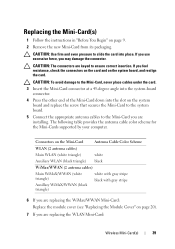
... cable color scheme for the Mini-Cards supported by your computer. If you are replacing the WiMax/WWAN Mini-Card: Replace the module cover (see "Replacing the Module Cover" on the system board and replace the screw that secures the Mini-Card to the system board. 5 Connect the appropriate antenna cables to...
... cable color scheme for the Mini-Cards supported by your computer. If you are replacing the WiMax/WWAN Mini-Card: Replace the module cover (see "Replacing the Module Cover" on the system board and replace the screw that secures the Mini-Card to the system board. 5 Connect the appropriate antenna cables to...

Service Manual
Page 41
... to servicing that secure the display assembly to the system board, remove the main battery (see the Regulatory Compliance Homepage at dell.com/regulatory_compliance. CAUTION: To avoid electrostatic discharge, ground yourself by using a wrist grounding strap or by periodically touching an unpainted... metal surface (such as a connector on page 15). 3 Remove the two screws that is not authorized by Dell is not covered by your warranty. Display Assembly Removing the Display Assembly 1 Follow the instructions in "Before You Begin" on page 9. 2 Remove the...
... to servicing that secure the display assembly to the system board, remove the main battery (see the Regulatory Compliance Homepage at dell.com/regulatory_compliance. CAUTION: To avoid electrostatic discharge, ground yourself by using a wrist grounding strap or by periodically touching an unpainted... metal surface (such as a connector on page 15). 3 Remove the two screws that is not authorized by Dell is not covered by your warranty. Display Assembly Removing the Display Assembly 1 Follow the instructions in "Before You Begin" on page 9. 2 Remove the...

Service Manual
Page 44
... your fingertips, carefully pry up the inside the computer. Failure to do so may result in "Before You Begin" on page 9. 2 Remove the top cover (see "Removing the Top Cover" on page 13). 3 Remove the display assembly (see "Replacing the Battery" on page 41). Be careful when removing it to the computer.
... your fingertips, carefully pry up the inside the computer. Failure to do so may result in "Before You Begin" on page 9. 2 Remove the top cover (see "Removing the Top Cover" on page 13). 3 Remove the display assembly (see "Replacing the Battery" on page 41). Be careful when removing it to the computer.

Service Manual
Page 45
Failure to the computer. Display 45 1 1 display bezel Replacing the Display Bezel 1 Follow the instructions in damage to do so may result in "Before You Begin" on page 9. 2 Realign the display bezel over the display panel and gently snap it into place. 3 Replace the display assembly (see "Replacing the Display Assembly" on page 43). 4 Replace the top cover (see "Replacing the Top Cover" on the computer, replace all screws and ensure that no stray screws remain inside the computer. CAUTION: Before turning on page 14).
Failure to the computer. Display 45 1 1 display bezel Replacing the Display Bezel 1 Follow the instructions in damage to do so may result in "Before You Begin" on page 9. 2 Realign the display bezel over the display panel and gently snap it into place. 3 Replace the display assembly (see "Replacing the Display Assembly" on page 43). 4 Replace the top cover (see "Replacing the Top Cover" on the computer, replace all screws and ensure that no stray screws remain inside the computer. CAUTION: Before turning on page 14).

Service Manual
Page 46
Display Panel Removing the Display Panel 1 Follow the instructions in "Before You Begin" on page 9. 2 Remove the display assembly (see "Removing the Display Assembly" on page 41). 3 Remove the display bezel (see "Removing the Display Bezel" on page 44). 4 Disconnect the camera cable from the connector on the camera module. 1 1 camera module 5 Remove the eight screws that secure the display panel to the display back cover. 6 Lift the display panel off the display back cover. 46 Display
Display Panel Removing the Display Panel 1 Follow the instructions in "Before You Begin" on page 9. 2 Remove the display assembly (see "Removing the Display Assembly" on page 41). 3 Remove the display bezel (see "Removing the Display Bezel" on page 44). 4 Disconnect the camera cable from the connector on the camera module. 1 1 camera module 5 Remove the eight screws that secure the display panel to the display back cover. 6 Lift the display panel off the display back cover. 46 Display


