Specifications
Page 1
... Regulatory model: P39F | Type: P39F003 Computer model: Inspiron 15-5557 NOTE: The images in the United States and/or other marks and names mentioned herein may differ from your computer depending on the configuration you ordered. Dell™ and the Dell logo are trademarks of their respective companies. 2015‑08 Rev. and international copyright and intellectual property laws. Inspiron 15 5000 Series Views Specifications...
... Regulatory model: P39F | Type: P39F003 Computer model: Inspiron 15-5557 NOTE: The images in the United States and/or other marks and names mentioned herein may differ from your computer depending on the configuration you ordered. Dell™ and the Dell logo are trademarks of their respective companies. 2015‑08 Rev. and international copyright and intellectual property laws. Inspiron 15 5000 Series Views Specifications...
Specifications
Page 8
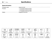
Views System information Computer model Processor Chipset Specifications Inspiron 15-5557 • 6th Generation Intel Core i3 ULV • 6th Generation Intel Core i5 ULV • 6th Generation Intel Core i7 ULV Integrated in processor Dimensions and weight System information Memory Ports and connectors Communications Video Audio Storage Media-card reader Display Keyboard Camera Touch pad Battery Power adapter Computer environment
Views System information Computer model Processor Chipset Specifications Inspiron 15-5557 • 6th Generation Intel Core i3 ULV • 6th Generation Intel Core i5 ULV • 6th Generation Intel Core i7 ULV Integrated in processor Dimensions and weight System information Memory Ports and connectors Communications Video Audio Storage Media-card reader Display Keyboard Camera Touch pad Battery Power adapter Computer environment

Specifications
Page 10
Views Ports and connectors External: Network USB Audio/video Internal: M.2 Specifications One RJ45 port • One USB 2.0 port • Two USB 3.0 ports • One HDMI port • One headset (headphone and microphone combo) port One M.2 slot for Wi-Fi, Intel WiDi (optional), and Bluetooth combo card Dimensions and weight System information Memory Ports and connectors Communications Video Audio Storage Media-card reader Display Keyboard Camera Touch pad Battery Power adapter Computer environment
Views Ports and connectors External: Network USB Audio/video Internal: M.2 Specifications One RJ45 port • One USB 2.0 port • Two USB 3.0 ports • One HDMI port • One headset (headphone and microphone combo) port One M.2 slot for Wi-Fi, Intel WiDi (optional), and Bluetooth combo card Dimensions and weight System information Memory Ports and connectors Communications Video Audio Storage Media-card reader Display Keyboard Camera Touch pad Battery Power adapter Computer environment

Specifications
Page 17
... Memory Ports and connectors Communications Video Audio Storage Media-card reader Display Keyboard Camera Touch pad Battery Power adapter Computer environment These keys can change the behavior of shortcut keys. NOTE: You can be used to type alternate characters or to perform secondary functions. To type the alternate character, press Shift and the desired key. List of the shortcut keys by pressing Fn+Esc or by changing Function Key Behavior in BIOS setup program. Views Keyboard Type Shortcut keys Specifications • Standard keyboard • Backlit keyboard...
... Memory Ports and connectors Communications Video Audio Storage Media-card reader Display Keyboard Camera Touch pad Battery Power adapter Computer environment These keys can change the behavior of shortcut keys. NOTE: You can be used to type alternate characters or to perform secondary functions. To type the alternate character, press Shift and the desired key. List of the shortcut keys by pressing Fn+Esc or by changing Function Key Behavior in BIOS setup program. Views Keyboard Type Shortcut keys Specifications • Standard keyboard • Backlit keyboard...

Specifications
Page 18
Keyboard Shortcut keys Mute audio Decrease volume Increase volume Play previous track/chapter Play/Pause Play next track/chapter Switch to external display Search Toggle keyboard backlight (optional) Decrease brightness Increase brightness Turn off/on wireless Pause/Break Sleep Toggle Scroll Lock Toggle Fn-key lock
Keyboard Shortcut keys Mute audio Decrease volume Increase volume Play previous track/chapter Play/Pause Play next track/chapter Switch to external display Search Toggle keyboard backlight (optional) Decrease brightness Increase brightness Turn off/on wireless Pause/Break Sleep Toggle Scroll Lock Toggle Fn-key lock
Service Manual
Page 1
Inspiron 15 5000 Series Service Manual Computer Model: Inspiron 15-5557 Regulatory Model: P39F Regulatory Type: P39F003
Inspiron 15 5000 Series Service Manual Computer Model: Inspiron 15-5557 Regulatory Model: P39F Regulatory Type: P39F003

Service Manual
Page 4
Removing the memory modules 23 Prerequisites...23 Procedure...23 Replacing the memory modules 25 Procedure...25 Post-requisites 26 Removing the wireless card 27 Prerequisites...27 Procedure...27 Replacing the wireless card 29 Procedure...29 Post-requisites 30 Removing the fan 31 Prerequisites...31 Procedure...31 Replacing the fan 35 Procedure...35 Post-requisites 35 Removing the keyboard 36 Prerequisites...36 Procedure...36 Replacing the keyboard 39 Procedure...39 Folding the keyboard cables 39 Post-requisites 41 4
Removing the memory modules 23 Prerequisites...23 Procedure...23 Replacing the memory modules 25 Procedure...25 Post-requisites 26 Removing the wireless card 27 Prerequisites...27 Procedure...27 Replacing the wireless card 29 Procedure...29 Post-requisites 30 Removing the fan 31 Prerequisites...31 Procedure...31 Replacing the fan 35 Procedure...35 Post-requisites 35 Removing the keyboard 36 Prerequisites...36 Procedure...36 Replacing the keyboard 39 Procedure...39 Folding the keyboard cables 39 Post-requisites 41 4

Service Manual
Page 10
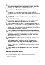
... Start screen, click or tap the power icon → Shut down . - Before working inside your computer CAUTION: To avoid damaging the components and cards, handle them by their electrical outlets. 4 Disconnect all cables such as telephone cables, network cables and so on, from your computer. 5 Disconnect all attached devices and peripherals, such as keyboard, mouse, monitor, and so on the configuration you are using a different operating...
... Start screen, click or tap the power icon → Shut down . - Before working inside your computer CAUTION: To avoid damaging the components and cards, handle them by their electrical outlets. 4 Disconnect all cables such as telephone cables, network cables and so on, from your computer. 5 Disconnect all attached devices and peripherals, such as keyboard, mouse, monitor, and so on the configuration you are using a different operating...
Service Manual
Page 11
... bending any installed card from the media-card reader. Some cables have connectors with locking tabs or thumb-screws that shipped with the product or at the back of the computer. After you finish working inside your computer, read the safety information that you must disengage before connecting to the power source. When disconnecting cables, keep them by the Dell technical assistance...
... bending any installed card from the media-card reader. Some cables have connectors with locking tabs or thumb-screws that shipped with the product or at the back of the computer. After you finish working inside your computer, read the safety information that you must disengage before connecting to the power source. When disconnecting cables, keep them by the Dell technical assistance...

Service Manual
Page 13
After working inside your computer CAUTION: Leaving stray or loose screws inside your computer may severely damage your computer. 1 Replace all screws and ensure that no stray screws remain inside your computer. 2 Connect any external devices, peripherals, and cables you removed before working on your computer. 3 Replace any media cards, discs, and any other parts that you removed before working on your computer. 4 Connect your computer and all attached devices to their electrical outlets. 5 Turn on your computer. 13
After working inside your computer CAUTION: Leaving stray or loose screws inside your computer may severely damage your computer. 1 Replace all screws and ensure that no stray screws remain inside your computer. 2 Connect any external devices, peripherals, and cables you removed before working on your computer. 3 Replace any media cards, discs, and any other parts that you removed before working on your computer. 4 Connect your computer and all attached devices to their electrical outlets. 5 Turn on your computer. 13

Service Manual
Page 17
... follow the instructions in Before working inside your computer. Prerequisites Remove the base cover. Removing the battery WARNING: Before working inside your computer, read the safety information that secure the battery to the base frame. 2 Using the pull tab, slide and lift the battery off the base frame. 1 pull tab 3 battery 2 screws (4) 3 Turn the computer over, open the display, and press the power button for about...
... follow the instructions in Before working inside your computer. Prerequisites Remove the base cover. Removing the battery WARNING: Before working inside your computer, read the safety information that secure the battery to the base frame. 2 Using the pull tab, slide and lift the battery off the base frame. 1 pull tab 3 battery 2 screws (4) 3 Turn the computer over, open the display, and press the power button for about...

Service Manual
Page 20
2 Using the pull tab, slide the hard-drive assembly out of the base frame. 1 pull tab 2 screws (4) 3 hard-drive assembly 3 Disconnect the hard-drive cable from the hard drive. 1 hard-drive assembly 2 hard-drive cable 4 Remove the screws that secure the hard-drive bracket to the hard drive. 20
2 Using the pull tab, slide the hard-drive assembly out of the base frame. 1 pull tab 2 screws (4) 3 hard-drive assembly 3 Disconnect the hard-drive cable from the hard drive. 1 hard-drive assembly 2 hard-drive cable 4 Remove the screws that secure the hard-drive bracket to the hard drive. 20

Service Manual
Page 22
.... After working inside your computer, follow the steps in the hard-drive bracket and align the screw holes on the hard-drive bracket with the screw holes on the hard drive. 2 Replace the screws that secure the hard-drive bracket to the hard drive. 3 Connect the hard-drive cable to the base frame. Procedure 1 Place the hard drive in Before working inside your computer. Post-requisites 1 Replace the battery. 2 Replace the base cover...
.... After working inside your computer, follow the steps in the hard-drive bracket and align the screw holes on the hard-drive bracket with the screw holes on the hard drive. 2 Replace the screws that secure the hard-drive bracket to the hard drive. 3 Connect the hard-drive cable to the base frame. Procedure 1 Place the hard drive in Before working inside your computer. Post-requisites 1 Replace the battery. 2 Replace the base cover...

Service Manual
Page 23
... instructions in Before working inside your computer. Prerequisites 1 Remove the base cover. 2 Remove the battery. Procedure 1 Using your computer. For more safety best practices, see the Regulatory Compliance home page at www.dell.com/regulatory_compliance. After working inside your computer, follow the steps in After working inside your fingertips, pry apart the securing clips on each end of the memory-module slot until the memory module...
... instructions in Before working inside your computer. Prerequisites 1 Remove the base cover. 2 Remove the battery. Procedure 1 Using your computer. For more safety best practices, see the Regulatory Compliance home page at www.dell.com/regulatory_compliance. After working inside your computer, follow the steps in After working inside your fingertips, pry apart the securing clips on each end of the memory-module slot until the memory module...

Service Manual
Page 26
2 Slide the memory module firmly into the slot at an angle and press the memory module down until it . 1 securing clips (2) 3 tab 5 memory modules (2) Post-requisites 1 Replace the battery. 2 Replace the base cover. 2 memory-module slot 4 notch 26 NOTE: If you do not hear the click, remove the memory module and reinstall it clicks into place.
2 Slide the memory module firmly into the slot at an angle and press the memory module down until it . 1 securing clips (2) 3 tab 5 memory modules (2) Post-requisites 1 Replace the battery. 2 Replace the base cover. 2 memory-module slot 4 notch 26 NOTE: If you do not hear the click, remove the memory module and reinstall it clicks into place.
Service Manual
Page 49
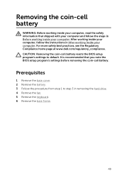
... the instructions in After working inside your computer. Prerequisites 1 Remove the base cover. 2 Remove the battery. 3 Follow the procedure from step 1 to default. CAUTION: Removing the coin-cell battery resets the BIOS setup program's settings to step 3 in removing the hard drive. 4 Remove the fan. 5 Remove the keyboard. 6 Remove the base frame. 49 After working inside your computer, follow the steps in Before working inside your computer. Removing the coin-cell battery WARNING: Before working inside...
... the instructions in After working inside your computer. Prerequisites 1 Remove the base cover. 2 Remove the battery. 3 Follow the procedure from step 1 to default. CAUTION: Removing the coin-cell battery resets the BIOS setup program's settings to step 3 in removing the hard drive. 4 Remove the fan. 5 Remove the keyboard. 6 Remove the base frame. 49 After working inside your computer, follow the steps in Before working inside your computer. Removing the coin-cell battery WARNING: Before working inside...

Service Manual
Page 64
... instructions in After working inside your computer. After working inside your computer, follow the steps in replacing the hard drive. 5 Replace the battery. 6 Replace the base cover. 64 For more safety best practices, see the Regulatory Compliance home page at www.dell.com/regulatory_compliance. Post-requisites 1 Replace the base frame. 2 Replace the keyboard. 3 Replace the fan. 4 Follow the procedure from step 3 to the system board. Replacing the status-light board...
... instructions in After working inside your computer. After working inside your computer, follow the steps in replacing the hard drive. 5 Replace the battery. 6 Replace the base cover. 64 For more safety best practices, see the Regulatory Compliance home page at www.dell.com/regulatory_compliance. Post-requisites 1 Replace the base frame. 2 Replace the keyboard. 3 Replace the fan. 4 Follow the procedure from step 3 to the system board. Replacing the status-light board...
Service Manual
Page 71
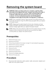
...: Replacing the system board removes any changes you replace the system board. For more safety best practices, see the Regulatory Compliance home page at www.dell.com/regulatory_compliance. Removing the system board WARNING: Before working inside your computer, read the safety information that you can reconnect the cables correctly after you have made to step 3 in removing the hard drive. 4 Remove the memory modules. 5 Remove the wireless card. 6 Remove the fan. 7 Remove the keyboard. 8 Remove...
...: Replacing the system board removes any changes you replace the system board. For more safety best practices, see the Regulatory Compliance home page at www.dell.com/regulatory_compliance. Removing the system board WARNING: Before working inside your computer, read the safety information that you can reconnect the cables correctly after you have made to step 3 in removing the hard drive. 4 Remove the memory modules. 5 Remove the wireless card. 6 Remove the fan. 7 Remove the keyboard. 8 Remove...
Service Manual
Page 74
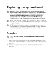
... the system board. NOTE: Replacing the system board removes any changes you replace the system board. You must make the desired changes again after you replace the system board. You must enter the Service Tag in After working inside your computer. NOTE: Your computer's Service Tag is stored in Before working inside your computer. Procedure CAUTION: Make sure that secure the system board to the BIOS using the BIOS setup program. For...
... the system board. NOTE: Replacing the system board removes any changes you replace the system board. You must make the desired changes again after you replace the system board. You must enter the Service Tag in After working inside your computer. NOTE: Your computer's Service Tag is stored in Before working inside your computer. Procedure CAUTION: Make sure that secure the system board to the BIOS using the BIOS setup program. For...

Service Manual
Page 100
... services Windows 8.1 and Windows 10 Dell Help & Support app Windows 10 Get started app Windows 8.1 Help + Tips app Accessing help in Windows 7 Click Start → Help and Support. Getting help and contacting Dell Self-help resources You can get information and help on . Online help for operating system www.dell.com/support/windows www.dell.com/support/linux Troubleshooting information, user manuals, setup instructions, product specifications, technical help in Windows 8, Windows 8.1, and Windows 10 In Windows search, type Help and Support...
... services Windows 8.1 and Windows 10 Dell Help & Support app Windows 10 Get started app Windows 8.1 Help + Tips app Accessing help in Windows 7 Click Start → Help and Support. Getting help and contacting Dell Self-help resources You can get information and help on . Online help for operating system www.dell.com/support/windows www.dell.com/support/linux Troubleshooting information, user manuals, setup instructions, product specifications, technical help in Windows 8, Windows 8.1, and Windows 10 In Windows search, type Help and Support...


