Specifications
Page 1
and international copyright and intellectual property laws. Dell and the Dell logo are trademarks of their respective companies. 2015 ‑ 04 Rev. Inspiron 15 5000 Series Views Specifications Copyright © 2015 Dell Inc. in this document may be trademarks of Dell Inc. This product is protected by U.S. A00 Regulatory model: P51F | Type: P51F002 Computer model: Inspiron 15-5555 NOTE: The images in the United States and...
and international copyright and intellectual property laws. Dell and the Dell logo are trademarks of their respective companies. 2015 ‑ 04 Rev. Inspiron 15 5000 Series Views Specifications Copyright © 2015 Dell Inc. in this document may be trademarks of Dell Inc. This product is protected by U.S. A00 Regulatory model: P51F | Type: P51F002 Computer model: Inspiron 15-5555 NOTE: The images in the United States and...
Specifications
Page 3
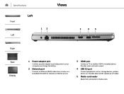
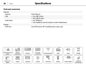
Provides data transfer speeds up to 5 Gbps. 5 Media-card reader Reads from and writes to your computer and charge the battery. 2 Network port Connect an Ethernet (RJ45) cable from a router or a broadband modem for network or internet access. 3 HDMI port Connect a TV or another HDMI‑in enabled device. Provides video and audio output. 4 USB 3.0 port Connect peripherals such as storage devices, printers, and so on. Specifications Front Left Left 12 Views 3 4 5 Right Base Display 1 Power-adapter port Connect a power adapter to provide power to media cards.
Provides data transfer speeds up to 5 Gbps. 5 Media-card reader Reads from and writes to your computer and charge the battery. 2 Network port Connect an Ethernet (RJ45) cable from a router or a broadband modem for network or internet access. 3 HDMI port Connect a TV or another HDMI‑in enabled device. Provides video and audio output. 4 USB 3.0 port Connect peripherals such as storage devices, printers, and so on. Specifications Front Left Left 12 Views 3 4 5 Right Base Display 1 Power-adapter port Connect a power adapter to provide power to media cards.
Specifications
Page 8
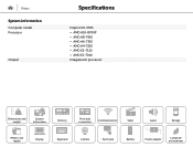
Views System information Computer model Processor Chipset Specifications Inspiron 15-5555 • AMD A10-8700P • AMD A8-7410 • AMD A6-7310 • AMD A4-7210 • AMD E2-7110 • AMD E1-7010 Integrated in processor Dimensions and weight System information Memory Ports and connectors Communications Video Audio Storage Media-card reader Display Keyboard Camera Touch pad Battery Power adapter Computer environment
Views System information Computer model Processor Chipset Specifications Inspiron 15-5555 • AMD A10-8700P • AMD A8-7410 • AMD A6-7310 • AMD A4-7210 • AMD E2-7110 • AMD E1-7010 Integrated in processor Dimensions and weight System information Memory Ports and connectors Communications Video Audio Storage Media-card reader Display Keyboard Camera Touch pad Battery Power adapter Computer environment
Specifications
Page 10
Views Ports and connectors External: Network USB Audio/video Internal: NGFF slot Specifications One RJ45 port • One USB 3.0 port • Two USB 2.0 ports • One HDMI port • One headphone and microphone combo (headset) port One NGFF slot for Wi-Fi and Bluetooth combo card Dimensions and weight System information Memory Ports and connectors Communications Video Audio Storage Media-card reader Display Keyboard Camera Touch pad Battery Power adapter Computer environment
Views Ports and connectors External: Network USB Audio/video Internal: NGFF slot Specifications One RJ45 port • One USB 3.0 port • Two USB 2.0 ports • One HDMI port • One headphone and microphone combo (headset) port One NGFF slot for Wi-Fi and Bluetooth combo card Dimensions and weight System information Memory Ports and connectors Communications Video Audio Storage Media-card reader Display Keyboard Camera Touch pad Battery Power adapter Computer environment
Specifications
Page 16
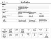
....43 in) 396.24 mm (15.60 in) Dimensions and weight System information Memory Ports and connectors Communications Video Audio Storage Media-card reader Display Keyboard Camera Touch pad Battery Power adapter Computer environment Views Display Type Refresh rate Operating angle Controls Resolution (maximum) Pixel pitch Dimensions: Height Width Diagonal Specifications • 15.6-inch HD Touch • 15.6-inch HD Non-touch • 15.6-inch FHD Touch 60 Hz 0 degrees (closed) to 135 degrees Brightness can be controlled using shortcut keys.
....43 in) 396.24 mm (15.60 in) Dimensions and weight System information Memory Ports and connectors Communications Video Audio Storage Media-card reader Display Keyboard Camera Touch pad Battery Power adapter Computer environment Views Display Type Refresh rate Operating angle Controls Resolution (maximum) Pixel pitch Dimensions: Height Width Diagonal Specifications • 15.6-inch HD Touch • 15.6-inch HD Non-touch • 15.6-inch FHD Touch 60 Hz 0 degrees (closed) to 135 degrees Brightness can be controlled using shortcut keys.
Specifications
Page 17
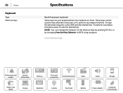
... information Memory Ports and connectors Communications Video Audio Storage Media-card reader Display Keyboard Camera Touch pad Battery Power adapter Computer environment These keys can change the behavior of shortcut keys. To type the alternate character, press Shift and the desired key. List of the shortcut keys by pressing Fn+Esc or by changing Function Key Behavior in BIOS setup program. Views Keyboard Type Shortcut keys Specifications Backlit keyboard (optional) Some keys on your keyboard have two symbols on them. NOTE: You can be used to type...
... information Memory Ports and connectors Communications Video Audio Storage Media-card reader Display Keyboard Camera Touch pad Battery Power adapter Computer environment These keys can change the behavior of shortcut keys. To type the alternate character, press Shift and the desired key. List of the shortcut keys by pressing Fn+Esc or by changing Function Key Behavior in BIOS setup program. Views Keyboard Type Shortcut keys Specifications Backlit keyboard (optional) Some keys on your keyboard have two symbols on them. NOTE: You can be used to type...
Specifications
Page 18
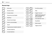
Keyboard Shortcut keys Mute audio Decrease volume Increase volume Play previous track/chapter Play/Pause Play next track/chapter Switch to external display Search Toggle keyboard backlight (optional) Decrease brightness Increase brightness Turn off/on wireless Sleep Toggle Fn-key lock Toggle between power and battery-status light/harddrive activity light Open application menu Pause/Break System request Toggle scroll lock
Keyboard Shortcut keys Mute audio Decrease volume Increase volume Play previous track/chapter Play/Pause Play next track/chapter Switch to external display Search Toggle keyboard backlight (optional) Decrease brightness Increase brightness Turn off/on wireless Sleep Toggle Fn-key lock Toggle between power and battery-status light/harddrive activity light Open application menu Pause/Break System request Toggle scroll lock
Service Manual
Page 1
Inspiron 15 5000 Series Service Manual Computer Model: Inspiron 15-5555 Regulatory Model: P51F Regulatory Type: P51F002
Inspiron 15 5000 Series Service Manual Computer Model: Inspiron 15-5555 Regulatory Model: P51F Regulatory Type: P51F002
Service Manual
Page 3
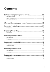
Contents Before working inside your computer 10 Before you begin 10 Safety instructions 10 Recommended tools 11 After working inside your computer 13 Removing the battery 14 Procedure...14 Replacing the battery 15 Procedure...15 Removing the optical drive 16 Prerequisites...16 Procedure...16 Replacing the optical drive 19 Procedure...19 Post-requisites 19 Removing the base cover 20 Prerequisites...20 Procedure...20 Replacing the base cover 21 Procedure...21 Post-requisites 21 3
Contents Before working inside your computer 10 Before you begin 10 Safety instructions 10 Recommended tools 11 After working inside your computer 13 Removing the battery 14 Procedure...14 Replacing the battery 15 Procedure...15 Removing the optical drive 16 Prerequisites...16 Procedure...16 Replacing the optical drive 19 Procedure...19 Post-requisites 19 Removing the base cover 20 Prerequisites...20 Procedure...20 Replacing the base cover 21 Procedure...21 Post-requisites 21 3
Service Manual
Page 4
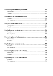
Removing the memory modules 22 Prerequisites...22 Procedure...22 Replacing the memory modules 24 Procedure...24 Post-requisites 25 Removing the hard drive 26 Prerequisites...26 Procedure...26 Replacing the hard drive 30 Procedure...30 Post-requisites 30 Removing the wireless card 31 Prerequisites...31 Procedure...31 Replacing the wireless card 33 Procedure...33 Post-requisites 33 Removing the coin-cell battery 34 Prerequisites...34 Procedure...34 Replacing the coin-cell battery 36 Procedure...36 Post-requisites 36 4
Removing the memory modules 22 Prerequisites...22 Procedure...22 Replacing the memory modules 24 Procedure...24 Post-requisites 25 Removing the hard drive 26 Prerequisites...26 Procedure...26 Replacing the hard drive 30 Procedure...30 Post-requisites 30 Removing the wireless card 31 Prerequisites...31 Procedure...31 Replacing the wireless card 33 Procedure...33 Post-requisites 33 Removing the coin-cell battery 34 Prerequisites...34 Procedure...34 Replacing the coin-cell battery 36 Procedure...36 Post-requisites 36 4

Service Manual
Page 10
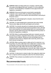
... their electrical outlets. 4 Disconnect all cables such as telephone cables, network cables and so on, from your computer. 5 Disconnect all attached devices and peripherals, such as keyboard, mouse, monitor, and so on the configuration you ordered. NOTE: The images in this document may differ from your computer depending on , from your computer. 6 Remove any media card and optical disc from potential damage and ensure...
... their electrical outlets. 4 Disconnect all cables such as telephone cables, network cables and so on, from your computer. 5 Disconnect all attached devices and peripherals, such as keyboard, mouse, monitor, and so on the configuration you ordered. NOTE: The images in this document may differ from your computer depending on , from your computer. 6 Remove any media card and optical disc from potential damage and ensure...
Service Manual
Page 11
...: Press and eject any connector pins. CAUTION: To disconnect a network cable, first unplug the cable from your computer and then unplug the cable from the media-card reader. WARNING: Before working inside the computer, replace all power sources before opening the computer cover or panels. WARNING: Disconnect all covers, panels, and screws before connecting to the power source. CAUTION: Before touching anything inside your computer, ground yourself by...
...: Press and eject any connector pins. CAUTION: To disconnect a network cable, first unplug the cable from your computer and then unplug the cable from the media-card reader. WARNING: Before working inside the computer, replace all power sources before opening the computer cover or panels. WARNING: Disconnect all covers, panels, and screws before connecting to the power source. CAUTION: Before touching anything inside your computer, ground yourself by...

Service Manual
Page 13
After working inside your computer CAUTION: Leaving stray or loose screws inside your computer may severely damage your computer. 1 Replace all screws and ensure that no stray screws remain inside your computer. 2 Connect any external devices, peripherals, and cables you removed before working on your computer. 3 Replace any media cards, discs, and any other parts that you removed before working on your computer. 4 Connect your computer and all attached devices to their electrical outlets. 5 Turn on your computer. 13
After working inside your computer CAUTION: Leaving stray or loose screws inside your computer may severely damage your computer. 1 Replace all screws and ensure that no stray screws remain inside your computer. 2 Connect any external devices, peripherals, and cables you removed before working on your computer. 3 Replace any media cards, discs, and any other parts that you removed before working on your computer. 4 Connect your computer and all attached devices to their electrical outlets. 5 Turn on your computer. 13

Service Manual
Page 22
... follow the instructions in Before working inside your fingertips to carefully spread apart the securing clips on each end of memory modules may be different on your computer depending on the configuration you ordered. 1 Use your computer. For more safety best practices, see the Regulatory Compliance home page at dell.com/regulatory_compliance. Prerequisites 1 Remove the battery. 2 Remove the base cover. After working inside your...
... follow the instructions in Before working inside your fingertips to carefully spread apart the securing clips on each end of memory modules may be different on your computer depending on the configuration you ordered. 1 Use your computer. For more safety best practices, see the Regulatory Compliance home page at dell.com/regulatory_compliance. Prerequisites 1 Remove the battery. 2 Remove the base cover. After working inside your...

Service Manual
Page 25
2 Slide the memory module firmly into place. NOTE: If you do not hear the click, remove the memory module and reinstall it clicks into the slot at an angle and press the memory module down until it . 1 memory module 3 memory-module slot Post-requisites 1 Replace the base cover. 2 Replace the battery. 2 securing clips (2) 25
2 Slide the memory module firmly into place. NOTE: If you do not hear the click, remove the memory module and reinstall it clicks into the slot at an angle and press the memory module down until it . 1 memory module 3 memory-module slot Post-requisites 1 Replace the base cover. 2 Replace the battery. 2 securing clips (2) 25
Service Manual
Page 34
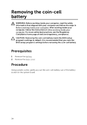
... instructions in Before working inside your computer. Procedure Using a plastic scribe, gently pry out the coin-cell battery out of the battery socket on the system board. 34 CAUTION: Removing the coin-cell battery resets the BIOS setup program's settings to default. After working inside your computer, follow the steps in After working inside your computer. Prerequisites 1 Remove the battery. 2 Remove the base cover. Removing the coin-cell battery WARNING: Before working...
... instructions in Before working inside your computer. Procedure Using a plastic scribe, gently pry out the coin-cell battery out of the battery socket on the system board. 34 CAUTION: Removing the coin-cell battery resets the BIOS setup program's settings to default. After working inside your computer, follow the steps in After working inside your computer. Prerequisites 1 Remove the battery. 2 Remove the base cover. Removing the coin-cell battery WARNING: Before working...

Service Manual
Page 63
... and open the display. 6 Connect the power-button board cable to step 8 in Before working inside your computer. Post-requisites 1 Follow the procedure from step 3 to the system board. For more safety best practices, see the Regulatory Compliance home page at dell.com/regulatory_compliance. After working inside your computer, follow the steps in "Replacing the computer base". 2 Replace the keyboard. 3 Replace the wireless card. 4 Replace the hard drive. 5 Replace the base cover. 6 Replace...
... and open the display. 6 Connect the power-button board cable to step 8 in Before working inside your computer. Post-requisites 1 Follow the procedure from step 3 to the system board. For more safety best practices, see the Regulatory Compliance home page at dell.com/regulatory_compliance. After working inside your computer, follow the steps in "Replacing the computer base". 2 Replace the keyboard. 3 Replace the wireless card. 4 Replace the hard drive. 5 Replace the base cover. 6 Replace...
Service Manual
Page 64
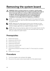
... page at dell.com/regulatory_compliance. You must make the desired changes again after you replace the system board. NOTE: Before disconnecting the cables from the system board, note the location of the connectors so that shipped with your computer and follow the instructions in After working inside your computer. Prerequisites 1 Remove the battery. 2 Remove the optical drive. 3 Remove the base cover. 4 Remove the hard drive. 5 Remove the wireless card. 6 Remove the keyboard. 7 Follow the...
... page at dell.com/regulatory_compliance. You must make the desired changes again after you replace the system board. NOTE: Before disconnecting the cables from the system board, note the location of the connectors so that shipped with your computer and follow the instructions in After working inside your computer. Prerequisites 1 Remove the battery. 2 Remove the optical drive. 3 Remove the base cover. 4 Remove the hard drive. 5 Remove the wireless card. 6 Remove the keyboard. 7 Follow the...
Service Manual
Page 69
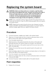
... open the display. 9 Slide the touchpad cable into the connector and press down on the latch to secure the cable to the system board. 3 Turn the system board over. 4 Slide the ports on the system board into the connector and press down on the system board with your computer and follow the instructions in the BIOS setup program after you replace the system board. Procedure 1 Connect the power-adapter port cable...
... open the display. 9 Slide the touchpad cable into the connector and press down on the latch to secure the cable to the system board. 3 Turn the system board over. 4 Slide the ports on the system board into the connector and press down on the system board with your computer and follow the instructions in the BIOS setup program after you replace the system board. Procedure 1 Connect the power-adapter port cable...
Service Manual
Page 100
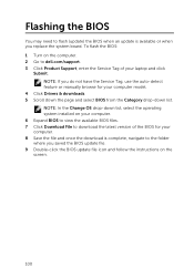
... dell.com/support. 3 Click Product Support, enter the Service Tag of your computer model. 4 Click Drivers & downloads. 5 Scroll down the page and select BIOS from the Category drop-down list, select the operating system installed on your computer. 6 Expand BIOS to view the available BIOS files. 7 Click Download File to the folder where you replace the system board. NOTE: In the Change OS drop-down list. Flashing the BIOS You may need to flash (update...
... dell.com/support. 3 Click Product Support, enter the Service Tag of your computer model. 4 Click Drivers & downloads. 5 Scroll down the page and select BIOS from the Category drop-down list, select the operating system installed on your computer. 6 Expand BIOS to view the available BIOS files. 7 Click Download File to the folder where you replace the system board. NOTE: In the Change OS drop-down list. Flashing the BIOS You may need to flash (update...


